A
few months ago I became interested in trying to make an automatic antenna
tuner. I had never thought about how they worked or what was used to
accomplish a product that would allow my radio to see a 1 to 1 match so I set
off to figure it out then apply what I had learned to make my own. I
almost always find a way to do something with my own twist so to speak so I
looked at autotuner designs that were already out there in the world. I
discovered that all of the tuners I looked at used a matrix or gang of
inductance coils along with input and output capacitance to reduce the SWR the
radio sees. In hindsight I understand why folks did their designs that
way. I had decided to purchase the parts for my design but later ended up
buying a cheap 3000 watt MFJ989C manual tuner and it came with everything I
needed to start my project.
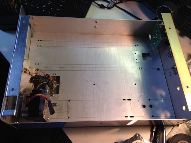
My
1st step was to strip the MFJ of all its components
to see what space I have to work with to install stepper motors to turn the
caps and inductor. I quickly learned that there was not enough room for
the steppers to be placed inside the cabinet to turn the caps but there was
enough room for the inductor if I moved it further back. I decided to use
servos to turn the variable capacitors since they only had to turn 180
degrees. At this point I did have to buy parts to make the connection of
the servo motors and the stepper to the shafts of each part.
I
took out the meter and made another front panel. I kept the SWR/Power bridge
from the MFJ.
While
I waited for the slow boat from China to arrive I started thinking about how I
manually tune my Palstar tuner to get the lowest SWR. So with trial and
error I did a basic design of the code. I need to say at this point how I
use my tuner is I listen for the noise level to increase as I adjust my
inductor. My 1st code did just this. It listened to the
noise level of the radio but a machine can’t tell the difference between quick
pop or someone on an adjacent frequency so it had no
accuracy using this method. I shifted gears and did it the old fashioned
way of finding the lowest SWR by turning the inductor and reading the SWR with
the processor. The capacitors were straight forward.
By
now my parts had come in and I started putting the parts back into the
MFJ. I left out the balun and the resistor used
for a dummy load. I also removed the coax switch so this tuner has no
bypass capability or use of the 2nd coaxial
input. I considered these as options because I needed to make sure the
tuner would work with my code before I invested money in vacuum relays.
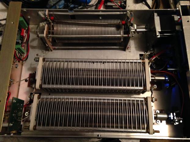
Above
is the finished tuner.
Let
me explain at this point I had been working on the code the whole time not sure
what the outcome would be when I loaded into the tuner. After a week of
building and finishing the code I put it to the test and it actually
worked! Not every time mind you but it performed
as I would expect 80% of the time. Not good enough but I have a good
starting point.
The
code is simple. I try to do simple so folks can understand what they read
when they look at my software. The inductor is moved in blocks meaning it
makes 4 turns then reads SWR I later changed this to 1 turn to get better
accuracy (and it wasn’t good enough either) at the cost of tuning speed.
The unit does make a lot of noise. When it started up the 1st time my wife who
is a Dr. Who fan said it “Sounded like the Tardis” and it does! It makes
the sound because I decided to use the most robust library for the stepper
motor the AccelStepper Library and it uses acceleration and deceleration so it
starts slow winds up to speed the slows down to stop at exactly 1 turn.
The trouble is when the motor turns the analog read function I use to measure
the SWR doesn’t read till it stops. I added a rotary encoder later to
make fine adjustments. The servos that turn the caps worked perfectly so
I didn’t make any changes to that section. At this point (without the
encoder) the tuner was accurate now 99% of the time but a problem arose from
day one. How do I calibrate the unit so it keeps track of where it is so
it will not bang the end of the roller inductor.
When
the tuner is 1st turned on it thinks it is at 0 position which is all the way to the front of the
chassis. 8800 is all the way to the back. That is 44
revolutions. If it is sitting at, say 20 then it will try to make 24
turns while banging on the end of the inductor. This is a bad thing so I
made some endstop switches and mounted them on each end of the inductor.
Now when it reaches the back it sets the position to 8800 and I tell it to go
to 0 (The front) it stops then moves back to the correct location where it left
off and continues on. Did I mention this thing makes noise? While that
plan worked it would calibrate itself every time it was turned on and that
wasn’t acceptable to me. I ended up writing a routine so when the
inductor has found its best SWR it will write its location to the EEPROM in the
Arduino processor. This worked perfectly. Now when it is turned off
and back on again it knows exactly where it is so it backs up to 0 and starts
the process of finding the lowest SWR again.
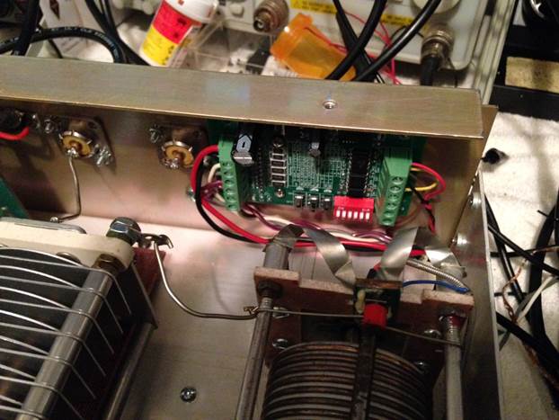
This
is the backstop I made and the stepper motor controller.
So
I still have it working 99% of the time. The answer was to add the rotary
encoder to make adjustments to the final resting stop. It does throw off
the EEPROM setting stored and can make use of the backstops to recalibrate but
it isn’t often enough for me to fret over.
Now
I want to display the power output and the SWR but I am out of pins to use
except for the serial TX and RX. I used a 2nd Arduino with a TFT
display/ touchscreen shield and connected it to the serial TX of the main
Arduino. On the display I connected it to the serial RX. Now all my
debug information shows up on the TFT screen. It didn’t work very well
and it had me frustrated to the point I put it to the side for weeks at a time
while I tried to make it display the data on each print from the main
Arduino. Through trial and a lot of error I got it working as well.
It shows the position of the 2 caps as well as the inductor. It also
displays SWR and Power output on each line like I wanted it to.
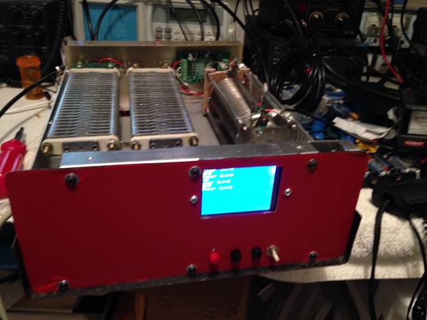
Above
is a picture before the encoder was installed and display was working properly.
I
have added the vacuum relays for antenna switching and bypass mode. I also updated the display to show all the parameters
while the tuner searches for the best match.
It is also better organized on the screen as well. The automatic band switching was interfaced
with the FT2000 and it sure does cut down on how long it takes to find a match. I was going to use a chip to translate the
band data from the radio but ended up using analog ports to accomplish this and
it works very well. I added a switch to
go from antenna 1 to 2. I don’t have
enough pins on the display shield to do touchscreen switching. At this point I have only 1 analog pin left
on the Arduino and all the other pins have been used. Bypass and tune modes are
selected by the rotary encoder momentary switch. If you can see the little
white button on the front, that is a reset switch for the Arduino that
calculates the match. I use it more as a
tune button that would need to be pressed every time you change bands.
The
code had been constantly changing so I haven’t posted it yet but will do so
maybe this weekend if I can finalize everything and run it through scenarios to
debug it. The code will be in 2
parts. 1 part is for the display and 1
for the tuner itself to calculate the best match. I will also start putting a parts list
together and try to get the information I have on paper (schematics) to and
electronic format. If you saw my
handwriting you would understand. I also
plan to go through the construction of the unit as well but it is pretty
straight forward. I don’t expect anyone
to make this exactly as I have.
This
is where I am at today. 2/11/16
Things
to do:
Test
the current code. It has been tested and is located here - Autotuner code It does have bugs on manual tuning.
Make
schematic.
Make
a Parts list.
Make
a “How To” page.
Add
a reset for the display. (No code changes)
Add
LCD for real-time Analog updates to power and SWR. (No code changes) (Add another Arduino and
create code for it to drive the LCD.)
**Work
on adding a mechanism to tell the tuner to “tune” when the band is changed. (When
not connected to a FT2K)
**Build
a small signal generator that can be tuned to the current band selected. (When not connected to a FT2K)
**Build
a frequency counter that can tell the Arduino what band to tune to when the
radio transmits momentarily. (When not
connected to a FT2K)
Look
into sharing pins so I can accomplish the statements above.
Add
photos of the current state of the tuner.
Consider using analog switches to free up pins on the Main Arduino.
**Options to add if desired (code changes)