One of the main drivers to look under the hood, as explained here, was to figure out how ISE was really behaving when multiple network interfaces are in place… I reverse engineered how ISE handles multiple NICs, here is what I found. This is a very poorly documented topic and a pretty complex one. The behaviour would depend on the type of traffic.
TCP connections #
Let’s first consider outbound sessions, the ones that are initiated from ISE. As an example, we can consider an SSH session from the appliance to some external server. This is the easiest use case, we would first look at the routing table for a specific route and if we don’t find anything, we fall back on the default gateway.
Where it gets interesting is to route the return traffic of inbound connections. Connections that are initiated from some external devices. The first thing to explain is that ISE is built on top of Linux and that one of the options to deal with multiple interfaces with that OS is to rely on Policy Based Routing. This is explained here. I don’t want to confuse you by throwing VRF in the picture, but the idea is similar, we have multiple independent routing tables and based on specific criteria we would select a specific table. This is exactly what ISE is doing. It is maintaining a routing table per interface. If a connection is arriving on a specific interface, it gets bound to that interface and in order to route the traffic back, we are going to look into the related routing table.
Here is a typical multi-NIC setup with two data interfaces and a management interface:
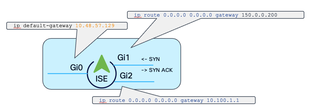
Rule of thumb: ISE would reply back on the same interface the initial packet arrived.
That would be too easy if there were no exceptions… A customer I had just explained this basic rule challenged me. Usually the default gateway would point to Gi0 but in their case, for some reasons, it was set on Gi1. SSH traffic was behaving as expected but they couldn’t get access to the GUI. They realised the HTTPS traffic was actually getting out of Gi1! Looking a bit deeper into the issue, that was actually caused by the API gateway. This feature is actually based on a container running Kong and the level of complexity to get there and out is a topic for another post. This should get fixed thanks to this DDTS (“eth0 does not use configured static route 0.0.0.0/0 in 3.x”).
RADIUS and Change of Authorization #
That was for TCP. If we now consider RADIUS traffic, things are a bit more complex… since RADIUS is connectionless by default, the same source/destination binding does not strictly apply. I believe for simple RADIUS traffic, the concept is similar. However, when we introduce RADIUS Change of Authorization, things are getting more interesting and this is when the application level need to come into play. Let’s first review the different kinds of CoA that are possible. I would classify them into three main categories:
PSN-Triggered #
This would be what comes naturally to mind when we are thinking CoA. We would face these messages typically in profiling or posture flow. They would be generated when some event happens around a RADIUS session. For example we learn some new attributes about an endpoint. These would allow us to refine the endpoint profile and to assign a different authorization…
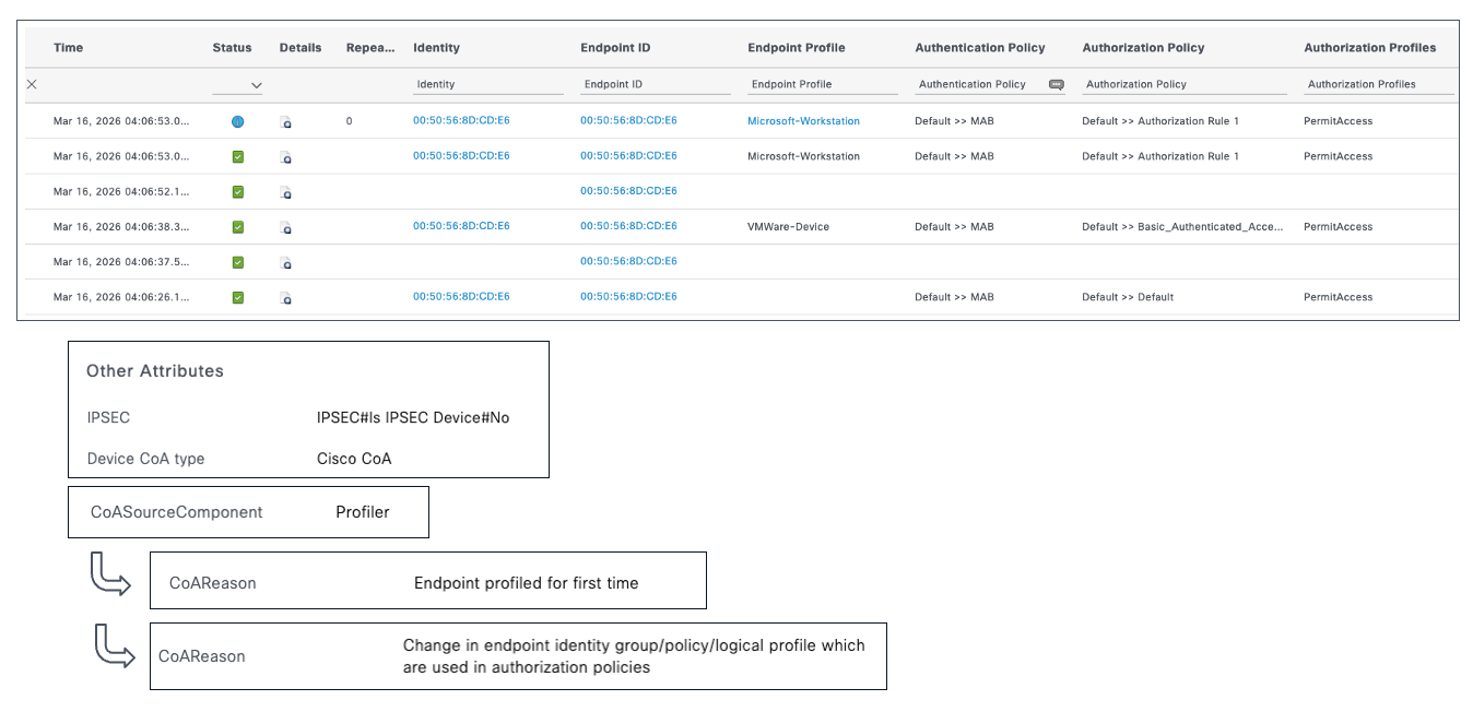
That means the ISE node needs to send a message to the authentication device…on the proper interface! The ISE PSN is actually keeping track of the different RADIUS sessions in a specific database. As part of a session entry, it records not only the IP address of the NAD but also the PSN interface from which the session has been initiated. That means that even if the UDP socket has been closed, it can find all the information required to generate the CoA out of the proper interface.
MnT-Triggered #
When you go to the Live Sessions tab, it is possible to kill or reauthorize a session by manually clicking the three little dots as illustrated on the following picture.
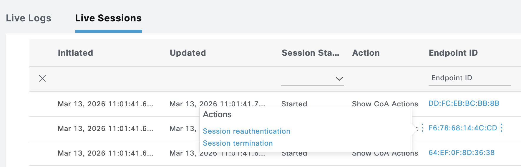
This is also done with a RADIUS CoA…
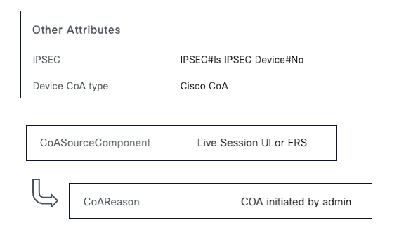
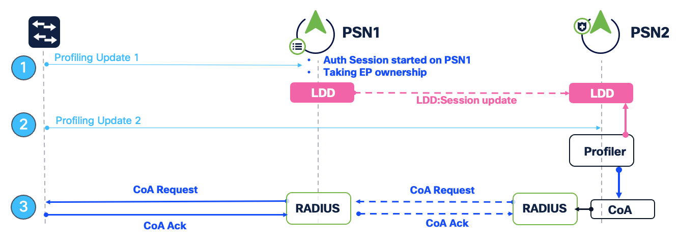
It might not be a well known fact, but these CoA are triggered by the MnT node. That’s actually the node where all the sessions from the ISE clusters are centralised. This is also done in a database consolidating the info received from the different PSN, including the IP address of the NAD and the related PSN interface. The MnT node would not send directly the CoA, it might not even have connectivity to the NAD! Instead, it will send a “Proxy-CoA” to the relevant PSN node. That packet will include all the information, including the interface to be used, required to send the actual CoA. This proxy-CoA would also be a RADIUS packet but using the UDP/3799 port. The PSN will then send the CoA over UDP/1700 and when receiving the acknowledgement from the NAD, reply to the MnT node. That flow is explained in the following illustration extracted from a great Cisco Live presentation about profiling:
Session-less CoA #
In some cases, a CoA is generated by ISE but would not be associated with any session. That would be the case for example for a CoA triggered as a notification for a Trustsec policy change.
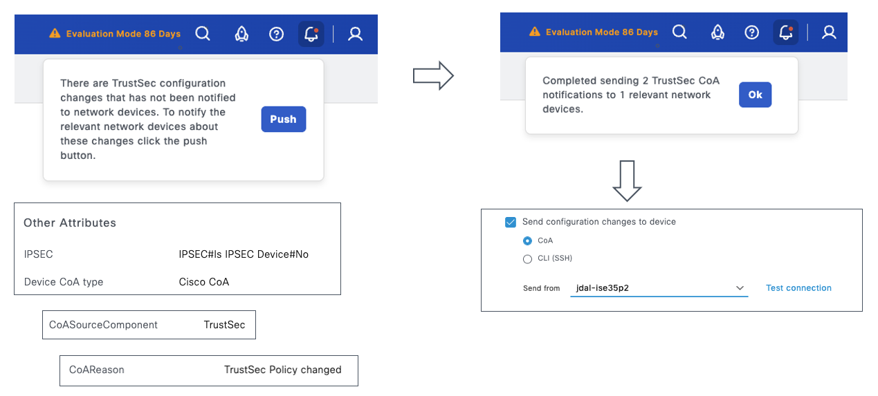
In that case, by default or as fallback, the PAN would be used to generate the CoA. It is also possible to define which ISE node would send the CoA for a specific NAD. It is however not possible to select which interface would be used for that purpose. This would be controlled by the routing table… which brings us to the next section.
Routing table quirks #
Talking about routing tables, don’t always trust the output. As we have seen earlier, it is possible to configure multiple 0.0.0.0 0.0.0.0 routes. In that case, for outbound traffic, the default gateway would take precedence. It is however possible to define as well multiple generic route. For example, the following is possible:
jdal-ise35p2/admin(config)# ip route 100.0.0.0 255.0.0.0 gateway 10.100.1.1
jdal-ise35p2/admin(config)# ip route 100.0.0.0 255.0.0.0 gateway 150.0.0.1
The routing table would look as follows:
jdal-ise35p2/admin# show ip route

Destination          Gateway              Iface
-----------          -------              -----
default              150.0.0.1            eth1
100.0.0.0/8          150.0.0.1            eth1
150.0.0.0/24         0.0.0.0              eth1
default              10.100.1.1           eth2
100.100.1.0/24       0.0.0.0              eth2
100.0.0.0/8          10.100.1.1           eth2
default              10.48.57.129         eth0
10.48.57.128/25      0.0.0.0              eth0
Which interface would be selected in that case if a connection has to be established with let’s say 100.0.0.1? The first one? The “smallest” next hop? Don’t scratch your head, there is no way to tell from that output. It is purely related to the order these routes have been configured. ISE would rely on the first route that has been configured.
I hope this post made you a bit more comfortable with using more than one NIC with your ISE nodes, there are still a few things left untouched, probably material for another post… stay tuned ;-)