|
|

This chapter provides information on the MultiChannel Interface Processor (MIP). (See Figure 10-1.)
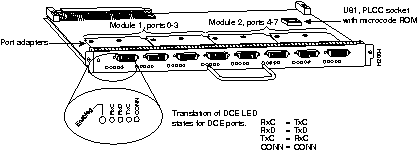
The MIP provides up to two channelized T1 or E1 connections via serial cables to a channel service unit (CSU). The MIP has one or two controllers for transmitting and receiving data bidirectionally at the T1 rate of 1.544 Mbps, or at the E1 rate of 2.048 Mbps. Each controller on a MIP can provide up to 24 T1 channel groups or 30 E1 channel groups. Each channel group is presented to the system as a serial interface that can be configured individually. The MIP can function as a concentrator for a remote site.
For both T1 and E1, there are no restrictions on slot locations or sequence; you can install the MIP in any available interface processor slot in a Cisco 7000 series or Cisco 7500 series router. The term module refers to the MIP card. A MIP module has one or two T1 or E1 adapters (or controllers). Do not mix T1 and E1 port adapters on a single MIP.
This section provides information about hardware and software requirements for the MIP.
For proper operation of the online insertion and removal (OIR) feature with the MIP, your Cisco 7000 series or Cisco 7500 series router must be operating with Cisco IOS Release 11.0(6) or later, or Cisco IOS Release 11.1(3) or later.
The MIP is compatible with any Cisco 7000 series router that is operating with the following software and microcode:
The MIP is available in the following interface configurations (with product numbers shown):
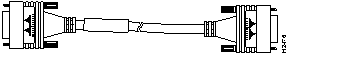
For T1, two standard serial cables, null-modem and straight-through, are available from Cisco Systems and other vendors for use with the MIP. The MIP T1 interface cables are used to connect your router to external CSUs. The MIP T1 interface cables have two male 15-pin DB connectors at each end to connect the MIP with the external CSU. Figure 10-2 shows the MIP interface cable, connectors, and pinouts. Table 10-1 lists the signal pinout for the null-modem cable, and Table 10-2 lists the signal pinout for the straight-through cable.

| DB-15 Connector | DB-15 Connector | ||
|---|---|---|---|
| Pin | Signal1 | Pin | Signal |
| 1 | Tx tip | 3 | Rx tip |
| 3 | Rx tip | 1 | Tx tip |
| 9 | Tx ring | 11 | Rx ring |
| 11 | Rx ring | 9 | Tx ring |
| DB-15 Connector | DB-15 Connector | ||
|---|---|---|---|
| Pin | Signal1 | Pin | Signal |
| 1 | Tx tip | 1 | Tx tip |
| 3 | Rx tip | 3 | Rx tip |
| 9 | Tx ring | 9 | Tx ring |
| 11 | Rx ring | 11 | Rx ring |
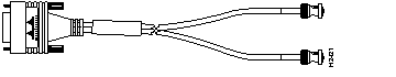
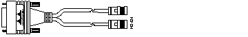
For E1, four serial cables are available from Cisco Systems for use with the MIP. All four have DB-15 connectors on the MIP end and either BNC, DB-15, Twinax, or RJ-48 connectors on the network end. Figure 10-3, Figure 10-4, Figure 10-5, and Figure 10-6 show the E1 interface cables. Table 10-3 lists the E1 cable pinouts.

| MIP End | Network End | |||||||
|---|---|---|---|---|---|---|---|---|
| DB-151 | BNC | DB-15 | Twinax | RJ-48 | ||||
| Pin | Signal2 | Signal | Pin | Signal | Pin | Signal | Pin | Signal |
| 9 | Tx tip3 | Tx tip | 3 | Rx tip | Rx-1 | Rx tip | 4 | Rx tip |
| 2 | Tx ring | Tx shield | 11 | Rx ring | Rx-2 | Rx ring | 5 | Rx ring |
| 10 | Tx shield | - | 4 | Rx shield | Shield | Rx shield | 6 | Rx shield |
| 8 | Rx tip | Rx tip | 1 | Tx tip | Tx-1 | Tx tip | 1 | Tx tip |
| 15 | Rx ring | Rx shield | 9 | Tx ring | Tx-2 | Tx ring | 2 | Tx ring |
| 7 | Rx shield | - | 2 | Tx shield | Shield | Tx shield | 3 | Tx shield |
Following are the E1 specifications:
Following are the T1 specifications:
Two standard T1 serial cables are available from Cisco Systems and other vendors for use with the MIP: null-modem and straight-through. These interface cables are used to connect your MIPs to additional MIPs or external CSUs, respectively.
You must use null-modem cables for MIP-to-MIP connections and straight-through cables for MIP-to-CSU connections. The T1 cables used to connect the MIP with external T1 equipment have DB-15 male connectors on each end.
Four E1 cables are available from Cisco Systems and other vendors for use with the MIP: BNC, Twinax, DB-15, and RJ-45. The E1 cables used to connect the MIP with external E1 equipment have a DB-15 male connector on the MIP end.
Connect the MIP cables as shown in Figure 10-7.

The MIP has three LEDs next to each port on its faceplate that indicate alarm or loop conditions on that port. (See Figure 10-8.)

When the system has reinitialized all interfaces, the enabled LED on the MIP should go on. The console screen will also display a message as the system discovers each interface during its reinitialization.
The following conditions must be met before the MIP is enabled:
If any one of these conditions is not met, or if the initialization fails, the enabled LED does not go on.
The three LEDs above each MIP port indicate the following:
Verify that the MIP is connected correctly as follows:
Step 1 While the system reinitializes each interface, observe the console display messages and verify that the system discovers the MIP. The system should recognize the MIP interface but leave it configured as down.
Step 2 When the reinitialization is complete, verify that the enabled LED on the MIP is on and remains on. If the LED does stay on, proceed to Step 5. If the enabled LED does not stay on, proceed to the next step.
Step 3 If the enabled LED on the MIP fails to go on, suspect that the MIP board connector is not fully seated in the backplane. Loosen the captive installation screws, then firmly push the top ejector down while pushing the bottom ejector up until both are parallel to the MIP faceplate. Tighten the captive installation screws. After the system reinitializes the interfaces, the enabled LED on the MIP should go on. If the enabled LED goes on, proceed to Step 5. If the enabled LED does not go on, proceed to the next step.
Step 4 If the enabled LED still fails to go on, remove the MIP and try installing it in another available interface processor slot.
Step 5 Use the show interfaces or show controllers cbus command to verify the status of the MIP interface. (If the MIP interface is not configured, you must configure it using the procedures in the section "Configuring the MIP.")
If an error message displays on the console terminal, refer to the appropriate reference publication for error message definitions. If you experience other problems that you are unable to solve, contact a service representative for assistance.
If you want to change the configuration of an existing interface, you must enter configuration mode to configure it. If you replaced the MIP that was previously configured, the system will recognize the new MIP and bring it up in the existing configuration.
After you verify that the new MIP is installed correctly, use the privileged-level configure command to configure the new MIP controller. Be prepared with the information you will need, such as the following:
For a complete summary of the configuration options available and more detailed instructions for configuring the MIP, refer to the appropriate software configuration and command reference publications listed in the section "If You Need More Information," in the chapter "Using Interface Processors."
Configuring the MIP first requires privileged-level access to the EXEC command interpreter. (Refer to the section "Using the EXEC Command Interpreter" in the chapter "Using Interface Processors.") Also, privileged-level access usually requires a password. (Contact your system administrator, if necessary, to obtain privileged-level access.)
Cisco 7000 series and Cisco 7500 series routers identify an interface address by its interface processor slot number and port number in the format slot/port. Each MIP contains up to two E1 or T1 interfaces, and the port numbers are always 0 and 1. For example, the slot/port address of the two T1 interfaces on a MIP installed in interface processor slot 0 are 0/0 and 0/1; if installed in interface processor slot 1, the slot/port addresses change to 1/0 and 1/1.
By default, channelized E1 port adapters are set with capacitive coupling between the receive (Rx) shield and chassis ground. This provides direct current (DC) isolation between the chassis and external devices, as stated in the G.703 specification. Jumper J6 controls this function. To make changes, first remove the MIP from the chassis, then remove the E1 port adapter from the motherboard. Place one of the spare jumpers on J6 pins 1 and 2 or pins 2 and 3 (refer to Table 10-4), then replace the port adapter on the motherboard. Pin 1 of J6 is designated with a square. (See Figure 10-9.)

| Jumper | Pins and Impedance | Function | |
|---|---|---|---|
| J6 | 1 and 2 for 120 ohm | Controls capacitive coupling for either 120-ohm or 75-ohm operation. An installed jumper directly connects the Rx shield to chassis ground. | |
Following are instructions for a basic configuration: enabling a controller and specifying IP routing. You might also need to enter other configuration subcommands, depending on the requirements for your system configuration and the protocols you plan to route on the interface.
The channel groups must be mapped before the MIP controller can be configured.
Table 10-5 lists the T1 commands used to map the channel group. Table 10-6 lists the E1 commands used to map the channel group. The default variables are listed first in each table and variable definitions for all T1 and E1 channel group commands follow Table 10-6.
| Commands for T1 |
|---|
| controller t1 slot/port |
| clock source [line | internal] |
| linecode [ami | b8zs] |
| framing [sf | esf] |
| loopback [local | remote] |
| shutdown |
| channel-group number timeslots list [speed {56 | 48 | 64}] For speed, 56 is the default. |
| Commands for E1 |
| controller e1 slot/port |
| linecode [hdb3 | ami] |
| framing [crc4 | no-crc4] |
| loopback |
| shutdown |
| channel-group number timeslots list [speed {56 | 48 |64}] For speed, 64 is the default. |
Channel group commands are valid where the following conditions are met:
Depending on the type of adapters on your MIP, select from the following two sections to configure its interfaces:
The following steps describe a basic T1 configuration. Press the Return key after each step.
Step 1 At the privileged-mode prompt, enter configuration mode and specify that the console terminal will be the source of the configuration subcommands as follows:
conf t
Enter configuration commands, one per line. End with CNTL/Z.
Step 2 At the prompt, specify the controller to configure by entering the subcommand cont, followed by t1, and slot/port (interface processor slot number/port). The example that follows is for the MIP in interface processor slot 0, interface port 1:
cont t1 0/1
Step 3 At the prompt, specify the clock source for the controller. The clock source command determines which end of the circuit provides the clocking.
clock source line
The clock source should only be set to use the internal clocking for testing the network or if the full T1 line is used as the channel group. Only one end of the T1 line should be set to internal.
Step 4 At the prompt, specify the framing type:
framing esf
Step 5 At the prompt, specify the linecode format:
linecode b8zs
Step 6 At the prompt, specify the channel-group modification command, channel group, and timeslots to be mapped. The following example shows channel group 0 and timeslots 1, 3 through 5, and 7 selected for mapping:
channel-group 0 timeslots 1,3-5,7 Step 7 At the prompt, specify the interface type, interface processor slot, interface port, and channel group to modify:
int serial 0/1:0
Step 8 At the prompt, assign an IP address and subnet mask to the interface with the ip address configuration subcommand as in the following example:
ip address 1.1.15.1 255.255.255.0
Step 9 Add any additional configuration subcommands required to enable routing protocols and adjust the interface characteristics.
Step 10 After including all of the configuration subcommands, to complete the configuration, press Ctrl-Z (hold down the Control key while you press Z) to exit configuration mode.
Step 11 Write the new configuration to memory as follows:
copy running-config startup-config
The system displays an OK message when the configuration is stored.
Step 12 Exit the privileged level and return to the user level by entering disable at the prompt as follows:
disable
Proceed to the section "Using show Commands to Check the Configuration" to check the T1 interface configuration.
The following steps describe a basic E1 configuration. Press the Return key after each step.
Step 1 At the privileged-mode prompt, enter configuration mode and specify that the console terminal will be the source of the configuration subcommands as follows:
conf t
Enter configuration commands, one per line. End with CNTL/Z.
Step 2 At the prompt, specify the controller to configure by entering the subcommand cont, followed by e1, and slot/port (interface processor slot number/port). The example that follows is for the MIP in interface processor slot 1, interface port 1:
cont e1 1/1
Step 3 At the prompt, specify the framing type:
framing crc4
Step 4 At the prompt, specify the linecode format:
linecode hdb3
Step 5 At the prompt, specify the channel-group modification command, channel group, and timeslots to be mapped. The example shows channel group 0 and timeslots 1, 3 through 5, and 7 selected for mapping.
channel-group 0 timeslots 1,3-5,7 Step 6 At the prompt, specify the interface type, interface processor slot, interface port, and channel group to modify:
int serial 1/1:0
Step 7 At the prompt, assign an IP address and subnet mask to the interface with the ip address configuration subcommand as in the following example:
ip address 1.1.15.1 255.255.255.0
Step 8 Add any additional configuration subcommands required to enable routing protocols and adjust the interface characteristics.
Step 9 After including all of the configuration subcommands, to complete the configuration, press Ctrl-Z (hold down the Control key while you press Z) to exit configuration mode.
Step 10 Write the new configuration to memory as follows:
copy running-config startup-config
The system displays an OK message when the configuration is stored.
Step 11 Exit the privileged level and return to the user level by entering disable at the prompt as follows:
disable
Proceed to the following section to check the E1 interface using show commands.
After configuring the new interface, use the show commands to display the status of the new interface or all interfaces. The following summary describes how to use the show commands to verify that the new interface is configured correctly:
Step 1 Use the show version command to display the system hardware configuration. Ensure that the list includes the new interface.
Step 2 Display all the current interface processors and their interfaces with the show controllers cbus command. Verify that the new MIP appears in the correct slot.
Step 3 Specify the new interfaces with the show interfaces serial slot/port command and verify that the first line of the display specifies the interface with the correct slot number. Also verify that the interface and line protocol are in the correct state: up or down.
Step 4 Display the protocols configured for the entire system and specific interfaces with the command show protocols. If necessary, return to configuration mode to add or remove protocol routing on the system or specific interfaces.
Step 5 Display the entire system configuration file with the show configuration command. Verify that the configuration is accurate for the system and each interface.
If the interface is down and you configured it as up, or if the displays indicate that the hardware is not functioning properly, ensure that the network interface is properly connected and terminated. If you still have problems, contact a service representative for assistance.
Following are descriptions and examples of the show controller command for T1 and E1. Descriptions are limited to fields that are relevant for verifying the configuration.
The show controller t1 command displays the status of the default T1 (which is specified in RFC 1406). The command show controller t1 slot/port command displays the verbose information for a particular T1 as follows:
Router# show cont t1
T1 0/1 is up.
  No alarms detected.
  Framing is ESF, Line Code is AMI, Clock Source is line
  Data in current interval (0 seconds elapsed):
     0 Line Code Violations, 0 Path Code Violations 0 Slip Secs,
0 Fr Loss Secs,
     0 Line Err Secs, 0 Degraded Mins 0 Errored Secs, 0 Bursty Err Secs,
     0 Severely Err Secs, 0 Unavail Secs
  Total Data (last 79 15 minute intervals):
     0 Line Code Violations, 0 Path Code Violations, 0 Slip Secs,
0 Fr Loss Secs,
     0 Line Err Secs, 0 Degraded Mins, 0 Errored Secs, 0 Bursty Err Secs,
     0 Severely Err Secs, 0 Unavail Secs
Router#
The show controller e1 command displays the status of the default E1 (which is specified in RFC 1406). The command show controller e1 slot/port displays the verbose information for a particular E1 as follows:
Router# show cont e1
E1 1/1 is up.
  No alarms detected.
  Framing is E1-crc, Line Code is hdb3
  Data in current interval (0 seconds elapsed):
     0 Line Code Violations, 0 Path Code Violations 0 Slip Secs,
0 Fr Loss Secs,
     0 Line Err Secs, 0 Degraded Mins 0 Errored Secs, 0 Bursty Err Secs,
     0 Severely Err Secs, 0 Unavail Secs
  Total Data (last 79 15 minute intervals):
     0 Line Code Violations, 0 Path Code Violations, 0 Slip Secs,
0 Fr Loss Secs,
     0 Line Err Secs, 0 Degraded Mins, 0 Errored Secs, 0 Bursty Err Secs,
     0 Severely Err Secs, 0 Unavail Secs
Router#
This completes the MIP configuration procedure.
Port adapters provide the ports for the E1 and T1 interfaces on the MIP. Each port adapter provides one port. Each MIP is shipped from the factory with one or two port adapters installed as fixed-configurations.
However, to alter capacitive coupling for 75-ohm and 120-ohm operation of the E1 port adapter (see the section "Configuring Jumper J6 on the E1 Port Adapter" on page 10-12), you first need to remove an existing E1 port adapter, then reinstall it.
 | Caution To prevent damaging the MIP and port adapters, remove and install port adapters only when it is necessary. Do not attempt to isolate faults or to troubleshoot MIPs or interfaces by swapping port adapters. The surface-mount circuitry on the port adapters will not tolerate excessive handling. Do not mix T1 and E1 port adapters on the same motherboard. |
You need the following tools to complete this procedure:
Port adapters are installed on each MIP at the factory. Each port adapter is anchored to the MIP with one plastic double-row vertical board-to-board (BTB) connector and four Phillips screws that extend through standoffs into the motherboard. (See Figure 10-10.) The port adapter is also anchored to the carrier faceplate with two jackscrews and two lock washers.
| Caution The surface-mounted components on the port adapters are extremely susceptible to ESD damage. Keep each port adapter in a separate antistatic bag until you are ready to install it. Always wear an ESD-preventive ground strap and handle boards as little as possible. When you must handle the board, limit contact to the board edges only, avoiding contact between the board and clothing. |
To remove an E1 port adapter from the MIP, refer to Figure 10-10 and perform the following steps:
Step 1 Remove the MIP from the router using the procedure in the section "Interface Processor Replacement Procedures" in the chapter "Using Interface Processors." (For specific online insertion and removal prerequisites, refer to the note in the section "MIP Hardware and Software Prerequisites" on page 10-2.)
Step 2 Ensure that the MIP is resting on an antistatic mat or on antistatic foam. You should still be wearing an ESD-preventive strap.
Step 3 Position the MIP so that it is in the same orientation shown in Figure 10-10.
Step 4 Locate the E1 port adapter to be removed and use a 3/16-inch nut driver to loosen the two jackscrews, one on either side of the cable connector. (See Figure 10-10.)

Step 5 Remove the jackscrews and washers and put them aside.
Step 6 Use a number 1 Phillips screwdriver to loosen and remove the four standoff screws. (See Figure 10-10.) The port adapter is now held in place only by the plastic BTB connector.
Step 7 While avoiding contact with any traces or components on the board, insert your thumb and forefinger under the extension behind the BTB connector and gently lift the adapter upward to dislodge it from the MIP connector. If the port adapter resists, rock it very slightly from side to side until it pulls free of the MIP connector.
| Caution To prevent damage to the MIP, do not pry the port adapter out with a screwdriver or any other tool. In particular, do not use the board stiffener for leverage. |
Step 8 When the port adapter is completely disconnected from the MIP connector, tilt the back of the port adapter up at about a 70-degree angle from vertical and slowly pull it up and out (using the orientation shown in Figure 10-10) and away from the faceplate. The MIP cable connector will pull out of the cutout in the faceplate.
Step 9 Reconfigure jumpers on the E1 port adapter. (To do so, refer to the section "Configuring Jumper J6 on the E1 Port Adapter" on page 10-12.) After you have set the jumpers, proceed to the section "Reinstalling a Port Adapter."
| Caution To prevent overheating chassis components, do not reinstall the MIP in the chassis unless all port adapters are in place. The empty port will allow cooling air to escape freely through the cutouts in the faceplate, which could misdirect the airflow inside the chassis and allow components on other boards to overheat. |
If necessary, refer to the previous section to remove an E1 port adapter from the MIP. Refer to Figure 10-11 while you perform the following steps to replace a port adapter:
Step 1 Ensure that the MIP is resting on an antistatic mat or on antistatic foam and position it with the same orientation as that shown in Figure 10-11. You should still be wearing an ESD-preventive ground strap.
Step 2 Handle the port adapter by the board edges only.
Step 3 Position the port adapter so that it is in the orientation shown in Figure 10-11: at about a 70-degree angle from vertical, component-side down, standoffs on the underside, and the external interface cable connector facing the inside of the carrier faceplate.
Step 4 As shown in Figure 10-11, partially insert the cable connector through the back of the cutout in the carrier faceplate. Do not force the cable connector through the cutout until the standoffs and BTB connector are aligned.
Step 5 With the cable connector partially inserted into the faceplate cutout, slowly lower the back (opposite) side of the port adapter. Continue to ease the cable connector through the cutout until the BTB connector and the MIP and port adapter meet and the standoffs on the MIP are aligned with the standoff holes in port adapter. Shift the port adapter until the cable connector is fully inserted through the cutouts and the standoffs are aligned with the standoff holes. (See Figure 10-11.)

Step 6 Place your fingers over the BTB connector and firmly (but gently) press down until the BTB connector mates with the MIP connector. If the connector resists, do not force it. Shift the port adapter around until the connectors mate properly.
Step 7 Insert the four long Phillips screws through the four port adapter holes and finger-tighten them. These screws extend through the standoffs and the MIP board and thread into the metal carrier.
Step 8 Install a lockwasher on each of the two jackscrews.
Step 9 Insert the two jackscrews through the front of the carrier faceplate and into the holes on either side of the cable connector.
Step 10 When all screws and connectors are aligned properly, use a Phillips screwdriver to tighten the four standoff screws and a 3/16-inch nut driver to tighten the two jackscrews. Do not overtighten any of these screws.
Step 11 Reinstall the MIP in the chassis. (To do so, follow the steps in the section "Installing an Interface Processor" in the chapter "Using Interface Processors.")
Step 12 Reconnect the network interface cables or other connection equipment to the MIP interface ports.
| Caution To prevent potential EMI and overheating problems, do not replace the MIP in the chassis unless all port adapters are installed. An empty port violates the EMI integrity of the system, and also allows cooling air to escape freely through the cutouts in the carrier faceplate, which could misdirect the airflow inside the chassis and allow components on other boards to overheat. |
When you insert the new MIP, the console terminal will display several lines of status information as it reinitializes the interfaces. Change the state of the interfaces to up and verify that the configuration matches that of the interfaces you replaced. Use the configure command or the setup command facility to configure the new interfaces. You do not have to do this immediately, but the interfaces will not be available until you configure them and bring them up.
After you configure the interfaces, use the show controller cbus, show controller T1, show controller E1 commands to display the status of the new interface. For complete command descriptions and instructions, refer to the appropriate software publications.
|
|
