|
|

Product Number MAS-7513-FAN=
The blower module assembly for the Cisco 7513 chassis is a spare part that can be replaced in the field.
This document provides recommendations for correct environmental conditions for the chassis and troubleshooting recommendations should you suspect a blower failure in your chassis.
This document discusses the procedures required to replace the blower module assembly.
The following topics are discussed:
The Cisco 7513 system blower is mounted in a module (drawer) located above the card cage on the interface processor end of the chassis. (See Figure 1.) It draws cooling air through the chassis interior to maintain an acceptable operating temperature for the internal components.
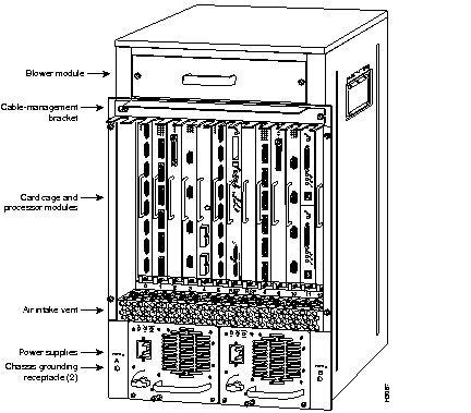
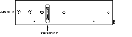
The blower module assembly comprises the blower, a printed circuit board (control board) mounted on a metal plate, three front panel LEDs, a power connector, and a metal case with a handle. A view of the end of the blower module (opposite the end with the handle) is shown in Figure 2.
The entire blower module assembly is available as a spare part. If any one of the internal parts fails (blower, control board, or LEDs), the entire assembly must be removed and replaced.
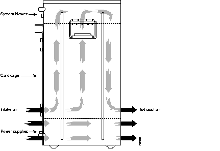
The blower module slides into the top of the Cisco 7513 chassis from the interface processor end of the router. (See Figure 1 and Figure 3.) The blower draws air in through the inlet vents below the chassis card cage, up through the card cage, processor modules, and other internal components, through the blower module, and out through the exhaust vents on the front of the chassis. Figure 3 shows the airflow path.
The front and back of the chassis must remain unobstructed to ensure adequate airflow and prevent overheating inside the chassis. (See the section "Site Environment.")
A blower control board on the blower module monitors and controls the operation of the variable-speed blower. The variable-speed feature enables quieter operation by allowing the blower to operate at less than maximum speed when doing so provides adequate cooling air to maintain an acceptable operating temperature inside the chassis.
Temperature sensors on the chassis interface and RSP2 monitor the internal air temperature. When the ambient air temperature is within the normal operating range, the blower operates at the slowest speed, which is 55 percent of the maximum speed.
If the temperature inside the chassis exceeds the normal range, the blower control board increases the blower speed to provide additional cooling air to the internal components. If the temperature continues to rise, the blower control board linearly increases the blower speed until the blower reaches full speed (100 percent). If the internal temperature exceeds the specified threshold, the system environmental monitor shuts down all internal power to prevent equipment damage from excessive heat.
If the system detects that the blower has failed, it will display a warning message on the console screen. If the condition is not corrected within two minutes, the entire system will shut down to avoid an overtemperature condition and shutdown.
The blower operates at 55 percent of capacity when it is possible to do so and maintain an acceptable operating temperature inside the chassis. If the temperature exceeds 23°C, the blower speed increases linearly until it reaches 100 percent. Although the blower supports quieter operation under normal conditions (approximately 62 dBa), the noise level when the blower is operating at 100-percent capacity is approximately 70 dBa. Therefore, the Cisco 7513 router is best suited for unattended or computer room use.
The router requires a dry, clean, well-ventilated, and air-conditioned environment. The internal blower pulls ambient air through the chassis to cool the internal components. To allow sufficient airflow, maintain a minimum of two inches of clearance at both the inlet and exhaust openings on the chassis. If the airflow is blocked or restricted, or if the inlet air is too warm, an overtemperature condition can occur. Under extreme conditions, the environmental monitor will shut down the power to protect the system components.
To help maintain normal operation and avoid unnecessary maintenance, plan your site configuration and prepare your site before installation. After installation, make sure that the site maintains an ambient temperature of 32 through 104°F (0 through 40°C), and keep the area around the chassis as free from dust as is practical.
If the temperature of the room air drawn into the chassis is higher than desirable, the air temperature inside the chassis may also be too high. This condition can occur when the wiring closet or rack in which the chassis is mounted is not ventilated properly, when the exhaust of one device is placed so it enters the air inlet vent of the chassis, or when the chassis is the top unit in an unventilated rack. Any of these conditions can inhibit air flow and create an overtemperature condition.
Because the inlet air flows into one part of the chassis and out another, other devices can be rack mounted with little or no clearance above and below the chassis. However, when mounting a router in a rack with other equipment, or when placing it on a table with other equipment located close by, ensure that the exhaust from other equipment does not blow into the inlet of the chassis. The inlet air is drawn in and exhausted as shown in Figure 3.
Table 1 lists the operating and nonoperating environmental site requirements. To maintain normal operation and ensure high system availability, maintain an ambient temperature and clean power at your site. The following ranges are those within which the router will continue to operate; however, a measurement that is approaching the minimum or maximum of a range indicates a potential problem. You can maintain normal operation by anticipating and correcting environmental anomalies before they approach the maximum operating range.
| Specifications | Minimum | Maximum |
|---|---|---|
| Temperature, ambient operating | 32°F (0°C) | 104°F (40°C) |
| Temperature, ambient nonoperating and storage | -4°F (-20°C) | 149°F (65°C) |
| Humidity, ambient (noncondensing) operating | 10% | 90% |
| Humidity, ambient (noncondensing) nonoperating and storage | 5% | 95% |
| Altitude, operating and nonoperating | Sea level | 10,000' (3050 m) |
| Vibration, operating | 5-200 Hz, 0.5 g (1 oct./min.) | - |
| Vibration, nonoperating | 5-200 Hz, 1 g (1 oct./min.) 200-500 Hz, 2 g (1 oct./min.) | - |
When the system power is on, the blower must be operational. If the system detects that the blower has failed or is failing, it will display a warning message on the console screen.
If the condition is not corrected within two minutes, the entire system will shut down to avoid an overtemperature condition and shutdown. The system uses a Hall Effect signal to monitor the blower.
The current to the blower and the magnetic field generated by the blower's rotation generates a voltage, which the system monitors to determine whether or not the blower is operating. If the monitored voltage signal drops below a specified value, the system assumes a blower failure and initiates a shutdown.
In the following example, the system has detected an out-of-tolerance fan, which it interprets as a fan failure. The failure message is displayed for two minutes before the system shuts down.
%ENVM-2-FAN: Blower has failed, shutdown in 2 minutes
If the system does shut down because of a blower failure, the system will display the following message on the console screen and in the show environment display when the system restarts:
Queued messages:
%ENVM-1-SHUTDOWN: Environmental Monitor initiated shutdown
For complete command descriptions and instructions, refer to the Router Products Command Reference publication.
If you suspect your blower has failed, check the following to help isolate the problem:
The show environment command display reports the current environmental status of the system. The report displays parameters that are out of the normal values. No parameters are displayed if the system status is normal. The example that follows shows the display for a system in which all monitored parameters are within Normal range. Following is sample output of the show env command:
Router# show env
All measured values are normal
If the environmental status is not normal, the system reports the worst-case status level in the last line of the display.
The show environment table command displays the temperature and voltage thresholds for each of the three RSP2 temperature sensors, for each monitored status level: low critical, low warning, high warning, and high critical. The slots in which the RSP2 can be installed are indicated in parentheses (6 and 7). Also listed are the shutdown thresholds for the processor boards and power supplies. Following is sample output of the show env table command:
Router# show env table
Sample Point    LowCritical    LowWarning     HighWarning    HighCritical
RSP(6) Inlet                                  101C/213F      101C/213F
RSP(6) Hotpoint                               101C/213F      101C/213F
RSP(6) Exhaust                                101C/213F      101C/213F
RSP(7) Inlet                                  101C/213F      101C/213F
RSP(7) Hotpoint                               101C/213F      101C/213F
RSP(7) Exhaust                                101C/213F      101C/213F
+12 Voltage     10.76          11.37          12.64          13.24
+5 Voltage      4.49           4.74           5.25           5.52
-12 Voltage     -10.15         -10.76         -13.25         -13.86
+24 Voltage     19.06          21.51          26.51          28.87
Shutdown boards at           101C/213F
Shutdown power supplies at   101C/213F
Before you begin replacing the blower, review the safety guidelines in this section to avoid injuring yourself or damaging the equipment. This section also lists of the tools and parts you need to perform this procedure.
The following guidelines will help to ensure your safety and protect the equipment. This list is not inclusive of all potentially hazardous situations, so be alert.
Follow these basic guidelines when working with any electrical equipment:
In addition, use the guidelines that follow when working with any equipment that is connected to telephone wiring or other network cabling.
Electrostatic discharge (ESD) damage, which can occur when electronic boards or components are handled improperly, can result in complete or intermittent failures.
Following are guidelines for preventing ESD damage:
 | Warning For safety, periodically check the resistance value of the antistatic strap. The measurement should be between 1 and 10 megohms. |
You need the following tools to install or replace a blower module:
The blower provides cooling air to the internal system components. If you determined that the blower or its control board has failed, you need to replace the blower module assembly. If you determined that the LED board inside the blower module assembly has failed, you need to replace the blower module assembly. The LED and blower control boards inside the blower module assembly are not separately replacable.
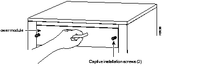
When viewing the chassis from the interface processor end, the blower module is located above the card cage (See Figure 4.) Two slotted captive screws hold the blower module in place.
| Warning It is not necessary to turn OFF system power before removing the blower module; however, when the power is ON and the blower module is removed, high current is exposed on the blower module power connector at the backplane. |
Follow these steps to replace the blower module.
Step 1 Locate the blower module, which is above the card cage on the noninterface processor end of the chassis. (See Figure 4.)
Step 2 Use the flat-blade screwdriver to loosen the captive screws that fasten each end of the blower module. (See Figure 4.)
| Warning Although the system should not be operating when you remove the blower module, it is not necessary to turn OFF system power before removing the blower module. However, with the system power ON and the blower module removed, high current is exposed on the blower module power connector at the backplane; do not insert conductive items into the empty blower module opening. After an operating blower module is removed, the blower impeller blades will continue to spin for approximately two minutes; do not insert anything into the module's vent holes while the impeller is spinning. |
 | Caution With chassis power ON and the blower module removed, no cooling air is circulating through the system. Replace the blower module before the system overheats. The system will shut down approximately two minutes after reaching the shutdown temperature threshold. |
Step 3 Grasp the handle on the front of the module and slowly pull the blower module straight out of the chassis. (See Figure 4.)
Step 4 Place the removed blower module in an antistatic bag for storage or return to the factory.
Step 5 Hold the handle of the new module with either your right or left hand (as long as you use both hands to handle the module) and with the intake vents on the blower module facing down and the "Insert This Side Up" label facing up, insert the new blower module into the chassis. Keep the module as straight as possible as you guide it into the chassis.
Step 6 When the blower is all the way into the chassis opening, tighten the captive installation screws on the front of the blower module.
This completes the blower module removal and replacement procedure.
Cisco Information Online (CIO) is Cisco Systems' primary, real-time support channel. Maintenance customers and partners can self-register on CIO to obtain additional content and services.
Available 24 hours a day, 7 days a week, CIO provides a wealth of standard and value-added services to Cisco's customers and business partners. CIO services include product information, software updates, release notes, technical tips, the Bug Navigator, configuration notes, brochures, descriptions of service offerings, and download access to public and authorized files.
CIO serves a wide variety of users through two interfaces that are updated and enhanced simultaneously--a character-based version and a multimedia version that resides on the World Wide Web (WWW). The character-based CIO (called "CIO Classic") supports Zmodem, Kermit, Xmodem, FTP, Internet e-mail, and fax download options, and is excellent for quick access to information over lower bandwidths. The WWW version of CIO provides richly formatted documents with photographs, figures, graphics, and video, as well as hyperlinks to related information.
You can access CIO in the following ways:
http://www.cisco.com
cio.cisco.com
For a copy of CIO's Frequently Asked Questions (FAQ), contact cio-help@cisco.com. For additional information, contact cio-team@cisco.com.
tac@cisco.com. To obtain general information about Cisco Systems, Cisco products, or upgrades, contact 800 553-6387, 408 526-7208, or cs-rep@cisco.com.
|
|