|
|

This appendix provides BMM connector pinouts and instructions for identifying and connecting cables and adapters to ports.
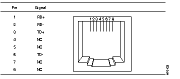
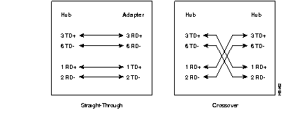
The 10BaseT and 100BaseTX ports use standard RJ-45 connectors for Category 5 UTP cabling (see Figure B-1). The 10BaseT and 100BaseTX ports have their transmit (TD) and receive (RD) pairs internally crossed. Figure B-2 shows the connector pinout, and Figure B-3 shows the straight-through and crossover cable schematics.

The 100BaseFX port connector (see Figure B-4) is a multimode fiber-optic SC (square connector).

The RJ-45-to-RJ-45 rollover cable and adapters supplied with the BMM are used to connect the BMM console port to a console terminal or modem. The following sections describe cables and adapters for the console port.
You can identify a rollover cable by comparing the two modular ends of the cable. Hold the cables side-by-side, with the tab at the back. The wire connected to the pin on the outside of the left plug should be the same color as the wire connected to the pin on the outside of the right plug. (See Figure B-5.) If your cable came from Cisco Systems, pin 1 is white on one connector, and pin 8 is white on the other (a rollover cable reverses pins 1 and 8, 2 and 7, 3 and 6, and 4 and 5).
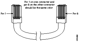
Table B-1, Table B-2, and Table B-3 list the pinouts for the console port, the RJ-45-to-RJ-45 rollover cable, and the following adapters:
| Console Port (DTE) | RJ-45-to-RJ-45 Rollover Cable | RJ-45-to-DB-9 Terminal Adapter | Console Device | |
|---|---|---|---|---|
| Signal | RJ-45 Pin | RJ-45 Pin | DB-9 Pin | Signal |
| RTS | 11 | 8 | 8 | CTS |
| DTR | 2 | 7 | 6 | DSR |
| TxD | 3 | 6 | 2 | RxD |
| GND | 4 | 5 | 5 | GND |
| GND | 5 | 4 | 5 | GND |
| RxD | 6 | 3 | 3 | TxD |
| DSR | 7 | 2 | 4 | DTR |
| CTS | 81 | 1 | 7 | RTS |
| Console Port (DTE) | RJ-45-to-RJ-45 Rollover Cable | RJ-45-to-DB-25 Terminal Adapter | Console Device | |
|---|---|---|---|---|
| Signal | RJ-45 Pin | RJ-45 Pin | DB-25 Pin | Signal |
| RTS | 11 | 8 | 5 | CTS |
| DTR | 2 | 7 | 6 | DSR |
| TxD | 3 | 6 | 3 | RxD |
| GND | 4 | 5 | 7 | GND |
| GND | 5 | 4 | 7 | GND |
| RxD | 6 | 3 | 2 | TxD |
| DSR | 7 | 2 | 20 | DTR |
| CTS | 81 | 1 | 4 | RTS |
| Console Port (DTE) | RJ-45-to-RJ-45 Rollover Cable | RJ-45-to-DB-25 Modem Adapter | Modem | |
|---|---|---|---|---|
| Signal | RJ-45 Pin | RJ-45 Pin | DB-25 Pin | Signal |
| RTS | 11 | 8 | 4 | RTS |
| DTR | 2 | 7 | 20 | DTR |
| TxD | 3 | 6 | 3 | TxD |
| GND | 4 | 5 | 7 | GND |
| GND | 5 | 4 | 7 | GND |
| RxD | 6 | 3 | 2 | RxD |
| DSR | 7 | 2 | 8 | DCD |
| CTS | 81 | 1 | 5 | CTS |
|
|