|
|

This chapter provides the following sections to troubleshoot BMM installation and performance:
The LEDs on the front panel are the quickest way to evaluate the operation of the bridge. The power-on self-test (POST) ensures that the switch is functioning properly at installation and when subsequently powered on. If the BMM does not operate properly or you are unable to access the management console, you can resolve these problems by using the diagnostic console described in the "Diagnostic Console" section in this chapter.
Statistics provided by the management console or SNMP management station can provide more details about the cause of connectivity and performance problems. For additional fault isolation information, see the descriptions of port, unit, and stack (RMON) statistics reports in the "Out-of-Band Management" chapter. To perform SNMP management, see the "In-Band Management" chapter.
The BMM front-panel LEDs facilitate troubleshooting during system operation. Table 5-1 lists symptoms and possible causes associated with system problems and provides corrective actions. BMM LEDs are shown in Figure 1-1 and Figure 1-2.
| Color | Cause | Corrective Action |
|---|---|---|
MOD LED off. | FastHub not powered. | Ensure the FastHub has power. |
| Reset in progress. | None. | |
| Module not properly seated in backplane connector. | Reinsert module. | |
| MOD LED flashing amber. | POST failure. | Attach a monitor to the console port to display the diagnostic console. See the "BMM POST Failures" section in this chapter for troubleshooting information. |
| MOD LED solid amber. | BMM in standby mode. | Use the diagnostic console described in the "Diagnostic Console Menu" section in this chapter to reset the FastHub. |
Port LED off. | FastHub not powered. | Ensure the FastHub has power. |
| Cable connection loose. | Verify connection at both ends of cable. | |
| Wrong cable type. | Verify cable type (crossover vs. straight-through). | |
| Incorrect wiring. | See the "Connectors and Cables" appendix for pinout information. | |
| Faulty cable. | Replace cable with a known good one. | |
| Port LED alternating green/amber.
| Receiving packets with errors due to excessive transmit collisions or the following types of errors: FCS, alignment, signal quality, or loss of carrier. | Verify port termination and check integrity of connected devices. |
Port LED solid amber | Device at other end malfunctioning. | Investigate device at other end of cable attached to disabled port. |
| Port disabled. | Enable port through in-band or out-of-band management. | |
| FastHub system LED amber. | BMM failed POST. | Replace BMM. |
When a FastHub is powered up or reset, the BMM begins its POST. POST failures are usually not fatal, unless they happen to the RAM test or the timer-interrupt test. When a non-fatal POST failure occurs, the BMM begins forwarding packets, but the FastHub system LED turns amber, and a POST-failure message displays on the BMM management console screen (see Figure 5-1). See Table 5-2 for POST test failure descriptions.
| Test Number | Item with Lost Functionality |
|---|---|
| 1 | Supervisor RAM. |
| 2 | EIA/TIA-232 console port. |
| 3 | Ethernet address. (Invalid Ethernet address stored in hardware.) |
| 4 | Timer interrupt. |
| 5 | Real-time clock. |
| 6 | Nonvolatile RAM. |
| 7 | Repeater port. (Repeater port loopback failure.) |
| 13 | Forwarding engine. |
| 14 | Forwarding engine SRAM. |
| 15 | Bridge buffer DRAM. |
| 16 | Bridge port control/status ring. |
| 17 | Content addressable memory (CAM) SRAM. |
| 18 | CAM. |
| 19 | Bridge port. (Bridge port loopback failure.) |
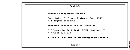
The diagnostic console is for those instances when the FastHub firmware has been corrupted or the present FastHub configuration prevents the firmware from executing properly. The diagnostic console log-in screen shown in Figure 5-2 is displayed when the firmware has been corrupted.

If you have defined a password, you are prompted for the password. If you have forgotten the password, you can obtain a factory-installed password by calling Cisco Systems and providing the Ethernet address displayed on the screen. If you have not defined a password, press Return to display the diagnostic console shown in Figure 5-3.
You might need the diagnostic console even though the firmware is valid. This could happen, for example, if the FastHub or BMM configuration prevents the firmware from executing properly and you cannot display the normal management console.
Use the following procedure to override the normal firmware startup and immediately display the diagnostic console (see Figure 5-3).
Step 1 Attach a monitor to the BMM console port.
Step 2 There are two ways to override the normal firmware startup:
Press the LED MODE button on the front panel of the FastHub and hold it in. While holding in the LED MODE button, press the BMM reset button.
Step 3 The diagnostic console log-in screen is displayed (see Figure 5-2).
Use the diagnostic console menu to troubleshoot firmware problems and, after resolving the problem, to bring up the firmware (see Figure 5-3).
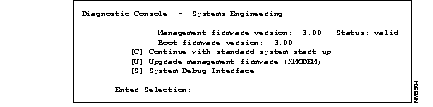
Management firmware version: Status:--Indicates the validity of the current firmware. If the current image is not valid, option C on the diagnostic console is not displayed.
Boot firmware version:--Displays the version of the write-protected part of the firmware that supports the diagnostic console.
[C] Continue with standard system startup--Select this option after you have resolved the firmware problems with options [U] or [S]. It brings up the debugged or upgraded firmware.
[U] Upgrade operation firmware (XMODEM)--Select this option to initiate a firmware upgrade. For instructions, refer to the "Diagnostic Console Upgrade" section in this chapter. This option works only with XMODEM and uses the default EIA/TIA-232 parameters:
[S] System Debug Interface--Select this option to display the System Debug Interface menu (see Figure 5-4). You can use the System Debug Interface menu to reset the BMM to factory defaults.
Use this menu to reset the BMM to factory defaults (see Figure 5-4). You can also use the management console to perform these functions.
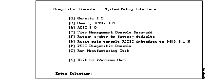
[G] Generic I/O--For Cisco personnel only.
[M] Memory CPU (I/O)--For Cisco personnel only.
[V] View Management Console password--Use this option to view the password currently assigned to the management console. If no password has been configured, the following message displays:
No password has been set.
[F] Return system to factory defaults--Use this option to return the FastHub to its factory default settings. All static and dynamic addresses are removed, as is the IP address and all configured system parameters. Enter Y or N and press Return. The changes take effect the next time the FastHub is reset.
[R] Reset main console RS232 interface to 9600, 8, 1, N--Select this option if you have lost the management console connection because of an improper modem configuration. The next time the FastHub is reset, the default RS-232 configuration is used.
[P] POST Diagnostic Console--For Cisco personnel only.
[T] Run Manufacturing Test--For Cisco personnel only.
Firmware upgrades transfer (download) an upgrade file directly into the BMM Flash memory. The out-of-band upgrade method and Diagnostic Console upgrade method use a serial link to the BMM console port. The in-band upgrade methods use a FastHub 100BaseT port and TFTP.
Only one upgrade attempt can be in progress at any one time. BMM firmware returns an error indication when it detects an upgrade conflict.
Use the following procedure to upgrade the firmware from the management console using the XMODEM protocol.
Step 1 From the Firmware Menu, select the option Initiate XMODEM upgrade.
The following prompt is displayed:
Step 2 Select OK.
The following prompt is displayed:
Step 3 Initiate the firmware transfer by entering an appropriate application-specific command.
When the upgrade completes successfully, the system resets and the new firmware begins to execute.
There are three ways to perform an in-band upgrade:
Use the following procedure to upgrade the firmware from the management console using the TFTP protocol.
Step 1 Display the BMM management console Firmware menu.
Step 2 Enable the option Server accept TFTP upgrade requests.
Step 3 Set the option Name or IP address of TFTP server to the name of the TFTP server containing the upgrade file. Note that if the first non-blank character is a number, the upgrade procedure assumes the server name is an IP address. If the first non-blank character is not a number, the upgrade procedure assumes the name is a fully-qualified domain name server name and uses the Domain Name System (DNS) protocol to resolve it to an IP address.
Step 4 Set the option Filename for firmware upgrade to the name of the firmware upgrade file.
Step 5 Select the option Initiate TFTP upgrade to initiate the firmware upgrade.
A second confirmation prompt allows you to verify the upgrade file path, the filename, and the server address. Once initiated, the BMM-directed method issues a file-open request to the TFTP server. Read requests then follow to obtain the file content.
The upgrade process uses the octet transfer mode, the opposite of the text transfer mode. The process either completes successfully or times out. The timeout interval is approximately 30 seconds. After a successful transfer of the upgrade file, the BMM resets and executes the new firmware.
Follow these steps to upgrade the BMM firmware using the SNMP agent:
Step 1 Determine the size of the upgrade file, then use the MIB object mrUpgradeFlashSize to ensure that there is available Flash memory.
Step 2 If necessary, use the following MIB objects to obtain information about the last upgrade performed:
Step 3 Use the MIB object mrUpgradeTFTPServerAddress to specify the name of the TFTP server where the upgrade file is located. Note that if the first non-blank character is a number, the upgrade procedure assumes the server name is an IP address. If the first non-blank character is not a number, the upgrade procedure assumes the name is a fully-qualified domain name server name and uses the Domain Name System (DNS) protocol to resolve it to an IP address.
You can also (optionally) provide a name or an IP address of a default gateway, such as when a TFTP server is located on a non-local IP network.
Step 4 Use the MIB object mrUpgradeTFTPLoadFilename to specify the name of the firmware upgrade file.
Step 5 Use the MIB object mrUpgradeTFTPInitiate to initiate the firmware upgrade.
Once initiated, the BMM-directed method issues a file-open request to the TFTP server. Read requests then follow to obtain the file content.
The upgrade process uses the octet transfer mode, the opposite of the text transfer mode. The process either completes successfully or times out. The timeout interval is approximately 30 seconds. After a successful transfer of the upgrade file, the BMM resets and executes the new firmware.
To perform the workstation-directed upgrade, you need a workstation equipped with a TFTP client application. Internet-based UNIX computers such as the Sun workstation usually come configured with such an application. Similar applications for DOS are available from a number of different vendors.
Using the TFTP client application, you direct the upgrade by issuing write requests to send an upgrade file to the BMM. After a successful transfer of the upgrade file, the BMM resets and executes the new firmware.
Although the workstation-directed upgrade gives you extra flexibility, it can present a security issue. Because there is no file authentication involved, the existing BMM firmware might be overwritten with outdated firmware. To prevent this, upgrade the firmware, and then set the MIB object mrUpgradeTFTPAccept to disabled; the BMM ignores future workstation-directed upgrade requests.
Use the following procedure to upgrade the firmware with the XMODEM protocol. This procedure is largely dependent on the modem software you are using.
Step 1 Display the Diagnostic Console menu, as described in the "Diagnostic Console" section in this chapter.
Step 2 Select the Diagnostic Console menu option U. The following message is displayed:
Step 3 Select option Y. The following messages are displayed:
Step 4 Select option 9 to transfer the image at 9,600 baud or option 5 to transfer at 57,600 baud. The following message is displayed:
Step 5 Configure your terminal application for the appropriate baud rate (9,600 or 57,600).
Step 6 Use the appropriate application-specific command to start the transfer.
The diagnostic console is displayed when the upgrade is complete.
Step 7 If you configured your terminal application for 57,600, reconfigure to 9,600 baud.
Step 8 Press C to restart the FastHub using the upgraded firmware.
Table 5-3 describes the various actions you can perform on the BMM to reset the FastHub or the BMM.
 | Caution Resetting to factory defaults is not reversible; all system parameters revert to factory defaults, and the original configuration is irrecoverable. |
| Caution Resetting to factory defaults causes all ports to come up enabled. Ports that were previously disabled through "Port status" are enabled after the reset. |
| Management Console System Menu | |||||
|---|---|---|---|---|---|
| Reset system | Reset to factory defaults1 | Reset repeater | Use BMM reset button | Remove or insert BMM | |
| Resets hardware and firmware | X | X | X | X |
|
| Runs BMM POST |
|
|
| X | X |
| Retains configured system parameters | X |
| X | X | X |
| Returns system parameters to factory defaults |
| X |
|
|
|
| Clears network-related statistics | X | X |
| X | X |
| Removes static addresses |
| X |
|
| X |
| Removes dynamic addresses | X | X |
| X | X |
|
|