|
|

This chapter describes how to use the web-based Switch Manager to change the switch configuration. The following topics provide the necessary information:
For further management options, the "SNMP Management" chapter describes how to use an SNMP device-management application, and the "Cisco IOS Management" chapter introduces the Cisco IOS command line interface.
The Catalyst 2900 Switch Manager is an embedded HTML web site residing in flash memory. You can assign bookmarks to pages and use the other browser functions as you would with any web site. The live image of the switch on the Switch Manager home page lets you monitor switch activity and confirm configuration changes without having to go into the wiring closet.
The Catalyst 2900 Switch Manager communicates with the switch by translating its HTML pages into Cisco IOS commands. These are the same commands that you can enter with the CLI.
Switch Manager pages function much like other graphical user interfaces (GUIs). You change the switch configuration by entering information into fields, adding and removing list items, or selecting check boxes. When you display a Switch Manager page, it contains the current values of switch features.
Changes made by entering information into fields become part of the running (current) configuration when you click Apply, a button that appears on every page. If you make a mistake and want to retype an entry, click Revert to undo the information you entered. You do not need to click Apply when you make changes to lists: items added or removed from Switch Manager lists immediately become part of the running configuration.
Online help is available on all pages.
The Catalyst 2900 software image is stored with other files in a file structure in flash memory. One of the files stored in this file structure is the configuration file that is loaded when the switch is restarted. If you want the running configuration to be the configuration used when the switch restarts, you need to save it to this file in flash memory. Follow the steps in the section "System Management" in this chapter to save the running configuration to the startup configuration file.
The switch must have an IP address before you can access Switch Manager. Use the Setup program when you install the switch to assign an IP address and other IP information. See the section "Starting the Switch for the First Time" in the "Installation" chapter for more information.
Follow these steps to access the Switch Manager:
Step 1 Start Netscape Communicator 4.xx or Internet Explorer 4.xx.
Step 2 Enter the IP address of the switch in the URL field.
Step 3 Click Open.
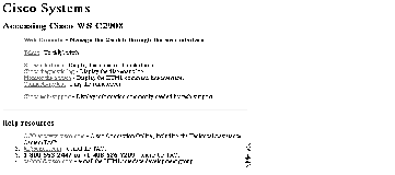
The Cisco Systems Access page (see Figure 4-1) is displayed.
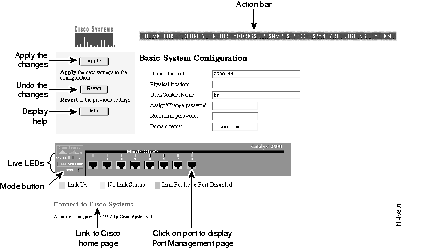
Step 4 Click Web Console to display the Catalyst 2900 Basic System Configuration page shown in Figure 4-3.
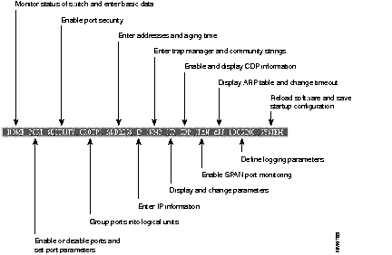
After you have started Switch Manager and displayed the switch home page (Figure 4-3), you can use the action bar at the top of each page to jump between pages. Figure 4-2 lists the functions that are available for each action bar selection.
You can access Cisco Connection Online (CCO), the Cisco Systems customer web site, from the Switch Manager home page. From CCO, you can download the latest software and display the latest Catalyst 2900 documentation.
The Basic System Configuration page shown in Figure 4-3 acts as the switch home page. You display it by clicking on Web Console on the Cisco Systems Access Page when you first start Switch Manager and by clicking on Home from the action bar.
This page contains a live image of the switch that displays the same information as the LEDs on the front of the switch. You can use this image in the following ways:
This information is usually entered once and not changed. Click Apply after entering information in the fields:
| Name of switch | Enter a name for the switch. |
| Physical location | Enter the location. |
| User/Contact person | Enter a name. |
| Domain name | Enter the name of the domain of the switch. See you system administrator for this information. |
Follow these steps to enter a password:
Step 1 In the Assign/Change password field, enter a character string.
Step 2 In the Reconfirm password field, reenter the same string.
Step 3 Click Apply.
The connection with the switch is broken. The browser prompts you for the new password: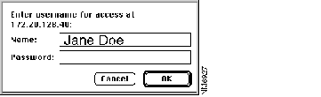
Step 4 Enter the same password and click OK.
See the "Recovering from a Lost or Forgotten Password" section in the "Troubleshooting" if you fail to enter or change the password.
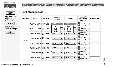
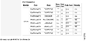
Use the Port Management page to enable and disable ports and to set other port parameters. You can display this page by clicking Ports on the action bar or by clicking directly on the image of the port on the Basic System Configuration page.
Figure 4-4 shows the ports listed in a table. Each port is described in the following columns:
| Module | A fixed port (system) or a module port (1 or 2). |
| Port | The interface number and port number. In the following example, the port is a 100BaseTX port, on interface 0 (a fixed port) and port number 1: FastEthernet0/1 |
Follow these steps to disable a port:
Step 1 Deselect the check box in the Enable column.
Step 2 Click Apply.
Step 3 To confirm the action, click on Home on the action bar to display the image of the Catalyst 2900. The port LED for the disabled port should be amber. If not, repeat the procedure and check the port LED on the front panel of the switch.
Catalyst 2900 ports can automatically configure their full-duplex capability and transmission speed to match that of an attached device. You can also set these parameters.
Use this page to display the current status of these port parameters and to change them.
Follow these steps to change the full-duplex and speed settings:
Step 1 Select the drop-down menu in the Duplex Setting column for the port.
Step 2 Select one of the options: Half, Full, or Auto (autosensing).
Step 3 Select the drop-down menu in the Speed column for the port.
Step 4 Select one of the options: 10, 100, or Auto (autosensing).
Step 5 Click Apply.
To confirm your changes, follow theses steps:
Step 6 Click Home on the action bar to display the image of the switch.
Step 7 Click Mode and release it when FDUP lights. If the port LED is off, the port is running in half duplex. If the port LED is green, the port is running in full duplex.
Step 8 Click Mode again and release it when 100 lights. If the port LED is off, the port is running at 10 Mbps. If the port LED is green, the port is running at 100 Mbps.
If the you cannot confirm the actions you requested, return to the Port Configuration page and make the changes again.
If an attached device does not support autonegotiation and is operating in full duplex, the Catalyst 2900 sets the port by default to half duplex. This configuration causes late collisions and FCS errors. To avoid this situation, take the port out of autonegotiation for speed and duplex, and set both to match the attached device.
By default the switch floods packets with unknown destination MAC addresses to all ports. As there are some configurations where this flooding is unnecessary, you can disable the flooding of unicast and multicast packets on a per-port basis.
Follow these steps to disable unicast and multicast flooding on a port:
Step 1 Deselect the unicast and multicast check boxes for the port.
Step 2 Click Apply.
See the "Flooding Controls" section of the "Concepts" chapter for more information on inhibiting flooding.
Use the Port Security page (Figure 4-5) to enable port security on a port and define the size of the address table for secured ports. Limiting the number of devices that can connect to a secure port can have the following advantages:
The following fields validate port security or indicate security violations:
| Current Secure Address Count | The number of addresses in the address table for this port. Secure ports have at least a 1 in this field. |
| Security Reject Count | The number of unauthorized addresses seen on the port. |
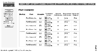
Follow these steps to enable port security on a port:
Step 1 Select the check box in the Security column for the port to secure.
Step 2 In the Violation Action column, select the action the switch takes when packets with an unauthorized address arrive on the port. Check Trap to issue an address-violation trap. Check Disable to disable the port.
Step 3 Click Apply.
Step 4 You can confirm that port security has been enabled by checking that the Current Secure Address Count has at least one address.
A secure port can have from 1 to 132 secure addresses associated with it. Setting the address table to have one address ensures the attached device has the full bandwidth of the port. Follow these steps to define the number of addresses that can be used by the secured port:
Step 1 Enter a number from 1 to 132 in the Maximum Secure Address Count field.
Step 2 Click Apply.
Use the Port Group Management page (see Figure 4-6) to create Fast EtherChannel port groups that act as single logical ports for high-bandwidth connections between switches or switches and servers.
You can create up to four port groups of any combination of ports, and a group can contain up to four ports. Switch features such as Spanning-Tree Protocol and flooding controls treat the port group as a single port. All ports, for example, are kept in the same Spanning-Tree state. With four 100BaseT ports operating in full-duplex mode, the combined bandwidth of the logical port is 800 Mbps.
Each port group has one port that carries all unknown multicast, broadcast, and Spanning-Tree Protocol packets.
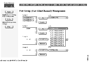
Step 1 Select the port and interface from the list of ports.
Step 2 Click <<Add<<.
To remove a port from a group:
Step 1 Select the port from the list.
Step 2 Click Remove.
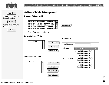
Use this page to manage the address tables that the switch uses to forward traffic between ports. Addresses are listed in the address tables with the MAC address, interface, and the port number. The following example associates MAC address 0000.2934.a0b3 with Fast Ethernet interface 0 (the switch) and port number 3.
0000.2934.a0b3 FastEthernet0/3
Dynamic addresses are destination MAC addresses that are learned by the switch and then dropped when they are not in use. Use the Aging Time field to define how long addresses that have not been seen should be retained by the switch.
Follow these steps to change the aging time for dynamic addresses:
Step 1 Highlight the contents of the Aging Time field.
Step 2 Enter the time, in seconds, after which an unused address is to be dropped. Possible values are from 10 to 1,000,000 seconds (about 11 and one-half days).
Step 3 Click Apply.
The "Address Learning" section in the "Concepts" chapter describes the Catalyst 2900 address-learning capabilities.
The secure address table contains secure MAC addresses and the ports with which they are associated. If a secure port receives a packet with a MAC address that has been statically entered and associated with another secure port, an alert can be generated and the port can be suspended or disabled.
Follow these steps to add a new secure address:
Step 1 Enter the MAC address in the MAC Address field.
Step 2 Select an interface and port from the Interface drop-down menu.
Step 3 Click <<Add<<.
\
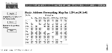
Static addresses are manually entered into the Static Address Table. They are not aged (dropped) from the table when not in use, and they are not lost when the switch resets. After you have entered a static address in the table, use the Static Address Forwarding Map (see Figure 4-8) to define the ports from which the address can receive packets and the ports to which the address can forward packets.
Follow these steps to add a static address:
Step 1 Enter the MAC address in the MAC Address field.
Step 2 Click <<Add<<. The Static Address Forwarding Map appears.
Step 3 On the Forwarding Map, select the ports from which the address can receive packets and the ports to which it can send packets.
Use the IP Management page (Figure 4-9) to assign IP addresses to the switch.
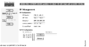
The IP address of the switch is entered and changed through the Setup program or the command line interface. The IP address displayed on this page is read only. When entering data in the IP Configuration fields, you can always select Revert to return the page to its previous state. You might need to contact a network administrator to obtain this information.
Follow these steps to enter the IP parameters for the switch:
Step 1 Enter the subnet mask for the switch.
Step 2 Enter the broadcast address for the switch.
Step 3 Enter the IP address of the default router or gateway.
This field can be filled automatically if a discovery protocol finds a router connected to a switch port.
Step 4 Enter the default domain name for the switch.
Step 5 Click Apply.
Domain name servers convert domain names into their corresponding IP address.
Follow these steps to add a domain name server:
Step 1 Enter the IP address of the server in the New Server field.
Step 2 Click <<Add<<.
To remove an address:
Step 1 Select an address in the Current Servers table.
Step 2 Click Remove.
Use the SNMP Management page (see Figure 4-10) to perform the following tasks:
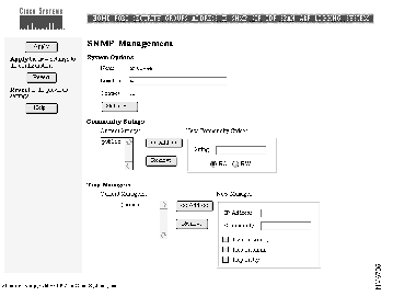
This information is used by network-management applications to identify the switch on a topology map. Follow these steps to enter information about the switch.
Step 1 Enter a name to be used for the switch.
Step 2 Enter the location of the switch.
Step 3 Enter the name of a person or organization.
Step 4 Click Apply.
Click Statistics to display the SNMP system information about the switch.
Community strings serve as passwords for SNMP messages. You can enter them with the following characteristics:
| Read only (RO) | Enables requests accompanied by the string to display MIB-object information. |
| Read write (RW) | Enables requests accompanied by the string to display MIB-object information and to set MIB objects. |
Follow these steps to add a community string:
Step 1 Enter a character string in the String field.
Step 2 Click RO (read only) or RW (read write).
Step 3 Click <<Add<<.
A trap manager is a management station that receives and processes traps. Create a trap manager by entering the IP address of the station and a community string.
Follow these steps to add a trap manager:
Step 1 Enter the IP address of the station to receive the trap in the IP Address field.
Step 2 Enter a character string in the Community field. This string can be of any length.
Step 3 Click <<Add<<.
Step 4 Select which class of traps the trap manager is to receive. Click the check box to enable one or all of the following:
(a) Trap on config-Generate traps on all changes to the switch configuration.
(b) Trap on snmp-Generate the supported SNMP traps.
(c) Trap on tty-Generate the serial-port related TTY traps.
Step 5 Click Apply.
Use this page to change parameters for Spanning-Tree Protocol, an industry standard for avoiding loops in switched networks. The page (see Figure 4-11) displays the Spanning-Tree settings for the current root switch and the settings this switch is to use when it becomes the root switch. Figure 4-12 is the second part of this page and is used to define port-level parameters.
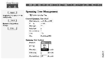
Spanning-Tree Protocol is enabled by default. To disable Spanning-Tree Protocol, follow these steps:
Step 1 Deselect Enable Spanning Tree.
Step 2 Click Apply.
The list of parameters under the heading Current Spanning Tree Root are read-only and could be defined on another switch. The MAC Address field contains the MAC address of the switch currently acting as the root.
The list of parameters under the heading Spanning Tree Options are the values that this switch would use as the root switch. Follow these steps to change the configuration of Spanning-Tree Protocol on this switch:
Change the following fields to change how your switch responds when Spanning-Tree protocol reconfigures itself.
Step 2 Click Apply.
Follow these steps to change the port-specific parameters:
Change the following fields to affect how the port responds if a loop is formed.
Step 2 You can select Port Fast if the port is connected to an end-station. Port Fast brings a port directly from a blocking state into a forwarding state. Only when the system is restarted and Spanning-Tree Protocol discovers the network does a port with Port Fast enabled begin forwarding with the normal cycle of status changes.
Step 3 Click Apply.
Use the following fields to check the status of ports that have been suspended by Spanning-Tree Protocol:
The Cisco Discovery Protocol (CDP) is a device-discovery protocol that the switch uses to maintain information about neighboring devices. Network-management applications that support CDP can then use this information to discover those devices.
Use the CDP Management page (see Figure 4-13) to enable CDP for the switch, set the global CDP parameters, and display information about neighboring devices.
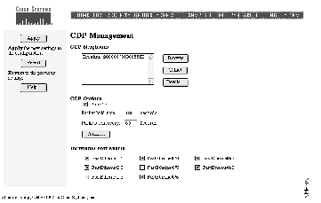
The CDP Neighbors list shows the devices with which this switch is exchanging CDP messages. Follow these steps to work with items in the list:
Step 1 Select an item in the list.
Click one of these buttons:
Some CDP parameters are global to the switch and some are entered on a per-port basis. Follow these steps to set the global parameters for CDP:
Step 1 Click the Run CDP check box to enable or disable CDP. CDP is enabled by default.
Step 2 In the Packet Hold Time field, enter the number of seconds (between 5 and 255) that a neighboring device retains the CDP neighbor information received from this switch.
If a neighboring device does not receive a CDP message before this hold time expires, the neighboring device drops this switch as a neighbor.
Step 3 In the Packets Sent Every field, enter the number of seconds (between 5 and 900) between transmission of CDP messages.
Step 4 Click Apply.
There can be times when you do not want CDP to exchange information with certain devices. In this case, disable the port with the devices attached to it.
Follow these steps to disable CDP on a port:
Step 1 Under the heading Individual Port Enable, select the check box next to the port and interface.
Step 2 Click Apply.
Use the SPAN Configuration page (Figure 3) to enable the SPAN port monitoring feature. SPAN lets you monitor traffic on a given port by forwarding incoming and outgoing traffic on the port to another port. You can then use an RMON probe to troubleshoot network problems from the data received from the port.
Any number of ports can be defined as monitor ports, and any combination of ports can be monitored. Follow these steps to configure your switch for SPAN:
Step 1 Click on the port or ports to be the monitor ports.
Step 2 Click on the ports to be monitored.
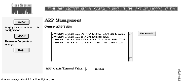
The Address Resolution Protocol (ARP) discovers the MAC address that corresponds to the IP address for a given host. Use this page (see Figure 4-15) to display the current addresses in the ARP table. You can also change the timeout for the ARP table.
You can manually add entries to the ARP table with the command line interface. ARP entries added manually to the table do not age and must be removed manually.
ARP entries are dropped from the ARP table after a configurable length of time. Click Remove All to clear the ARP cache. To change the timeout for a port:
Step 1 Enter a time, in seconds, between 1 and 4294967 in the ARP Cache Timeout Value field.
Step 2 Click Apply.
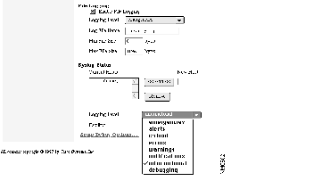
The switch generates traps and other messages when the configuration changes and when certain network or switch events occur. You can set the switch to write this information to the management console or to a buffer, file, or UNIX Syslog facility. Use this page (see Figure 4-16) to define the logging type and level of detail to log. Specify the amount of detail to log by selecting the appropriate severity level (see Figure 4-17).
You can define which traps the switch generates on the SNMP Management page. See the section "SNMP Management" in this chapter for more information.
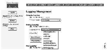
Select one of the following options to log switch activity and then click Apply:
| Console Logging | Select this option to write log information to the management console. |
| Buffer Logging | Select this option to write log information to a buffer in Flash memory. Enter the size of the buffer in the Buffer Size field.
Information is maintained in the buffer on a first-in, first-out basis. If the buffer is full and you click Show Buffer, the most-recent data is always displayed. |
| File Logging | Select this option to maintain a log file on an external server or in Flash memory. If the switch fails, it writes information about the cause of the failure to this file before functionality is lost.
Follow these steps to write to a file on a server: Step 1 Click Enable File Logging. Step 2 Select a severity level from the Logging Level menu. Step 3 Enter a TFTP URL and the file name, the appropriate XMODEM command, or flash:filename. Step 4 Enter a minimum and maximum file size, in bytes. Step 5 Click Apply. |
| Syslog | Select this option to use the UNIX Syslog facility to manipulate log information written to a UNIX host. Log information is sent to the UNIX host where it is then managed according to the facility established on the host. |
| Follow these steps to add a host to which log information is to be written:
Step 1 Enter the host IP address in the New Host field. Step 2 Click <<Add<<. Step 3 Click Apply. To use Syslog, you also need to define the facility that handles the log data. Follow these steps to select a facility: Step 1 Click on the Facility menu Step 2 Select a facility.
|
Cisco IOS can log eight levels of messages. When you select a severity level, the switch logs all Syslog message of that level and above. The default level is Errors.
Select a level from one of the following choices on the Logging Level menu:
| Emergencies | The switch is at risk of failing. |
| Alert | A condition exists that should be corrected immediately. |
| Critical | A critical condition exists, such as hard device errors. |
| Errors | Errors. |
| Warnings | Warning messages. |
| Notifications | Conditions that are not errors, but that could require special handling. |
| Information | Informational messages. |
| Debugging | Messages only used for debugging. |
Catalyst 2900 series switches support a file system that includes a compiled image and other files that are used when the switch resets. Use the System Management page (see Figure 4-18) to enter the file names and other information used by the switch when it restarts or resets.
Change the transmission speed of the console port by selecting one of the Baud Rate menu options shown in Figure 4-18. The change takes effect when you click Apply.
Click Details to display an ASCII version of the console port characteristics.
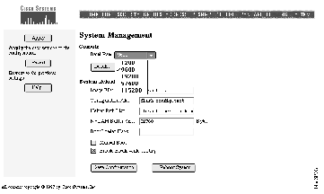
The switch configuration file contains the information you entered when you configured the switch. IP addresses, passwords, and any other parameters you entered are saved in this file and used when the switch restarts.
However, the configuration file does not always contain the configuration that is currently operating the switch. Changes made through the Switch Manager or the CLI take effect immediately but must be explicitly saved to be included in the startup configuration.
Use this page to save the running configuration to the startup configuration file. The following buttons control the switch startup:
| Save Configuration | Click to replace the startup configuration with the running configuration. |
| Reboot System | Click to restart the switch and load the startup configuration. |
This section describes the file system the switch maintains in flash memory. When you reset the switch, it looks for the files listed here to load along with the image file.
Follow these steps to change the switch reload options:
Enter the image file name and other details for reloading the system.
| Image File | Enter the path and name of the IOS image file to load when you reboot the system. |
| Configuration File | Enter the path and name of the startup configuration file that the image file reads to configure the switch. |
| Helper Path List | Enter the path and file name of the helper file to be loaded along the image file. Helper files can extend the functionality of the boot loader. Diagnostic software, for example, can be loaded along with the boot loader. |
| NVRAM Buffer Size | Enter the number of bytes to allocate for the NVRAM buffer. This buffer must be big enough to hold the configuration file. You can increase the buffer to a maximum of 65536 bytes.
To display the size of the configuration file, enter the following command on the command-line interface: switch#dir flash: |
| Boot Loader Flags | Enter -post to display all possible POST messages. |
| Manual Boot | Enable a pause in the boot sequence. You are prompted to enter a command on the CLI to load the software. |
| Enable Break while booting | Allow a break, such as an RS-232 break, to end the boot sequence. You can use this option to interrupt the boot with emulation software running on a remote workstation. |
Step 2 Click Apply.
Reviewers: is disabled a valid STP state?
|
|