|
|

Cisco Product Number = MEM-1000-8MD=
This document explains how to upgrade the DRAM SIMM in the Cisco 1003, Cisco 1004, and Cisco 1005 routers. You might need to upgrade the DRAM SIMM for some Cisco IOS feature sets or if the router is storing large routing or spoofing tables.
This document contains the following sections, which explain the DRAM SIMM upgrade procedure in detail:
The following tools are required to upgrade the DRAM SIMM on the router:
Before installing a DRAM SIMM, read the electrostatic discharge (ESD) instructions in this section to prevent damage to the equipment. ESD is a discharge of stored static electricity that can damage equipment and impair electrical circuitry. It occurs when electronic components are improperly handled and can result in complete or intermittent failures.
Following are guidelines for preventing ESD damage:
 | Caution To avoid damaging the equipment, periodically check the resistance value of the antistatic strap. The measurement should be between 1 and 10 megohms (Mohms). |
Take the following steps to remove the cover:
Step 1 Disconnect all cables from the rear panel. (Disconnecting the power cable turns OFF power to the router. Be sure the power cable is disconnected before proceeding.)
Step 2 Place the router on top of a flat, secure surface, such as a desk or table.
Step 3 Position the router so that the rear panel is facing you.
Step 4 Using a flat-blade screwdriver, remove the screw at the center of the rear panel. (See Figure 1.)

Step 5 Place your hands flat on top on the router chassis. With the heel of your hands, push down and back on the cover. (See Figure 2.) The cover will slide back approximately one-half inch.

Step 6 Place your thumbs on the top edge of the rear panel and grasp the bottom edges of the cover with your fingers. Lift upward with your fingers to remove the cover. (See Figure 3.) Place the cover aside.

Step 7 Proceed with the next section, "Replacing the DRAM SIMM."
Take the following steps to replace the DRAM SIMM:
Step 1 Locate the DRAM SIMM near the front of the system card.
Step 2 Locate the SIMM socket on the system card near the LEDs.
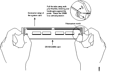
Step 3 Remove the existing DRAM SIMM. While pulling outward on the tabs to unlatch them, raise the SIMM to a vertical position and remove it from the SIMM socket. (See Figure 4.)
 | Caution To prevent damage, do not push on the center of the DRAM SIMM. Handle the DRAM SIMM carefully. |

Step 4 Position the new DRAM SIMM so that the polarization notch is located at the right end of the SIMM socket.
Step 5 Insert the new DRAM SIMM by sliding the end with the metal fingers into the SIMM socket at approximately a 45-degree angle to the system card. Gently rock the SIMM back into place until the latch on either side snaps into place. Do not use excessive force because the connector could break.
Step 6 Proceed with the next section "Replacing the Cover."
Take the following steps to replace the cover:
Step 1 Align the cover with the front edge of the bottom section of the chassis.
Step 2 Slowly close the cover, making sure not to bend any of the tabs on the side of the chassis. While closing the cover, it might be necessary to press inward on the tabs so that they fit inside the cover. (See Figure 5.)

Step 3 Place one hand on the front panel of the router, and place the heel of your other hand on the rear panel for stability. With the hand on the front panel of the router, push the cover toward you until it closes. (See Figure 6.)

Step 4 Replace the screw in the center of the rear panel, which you removed earlier. (See Figure 1.)
Step 5 Reconnect all cables to the router. (Reconnecting the power cable turns ON power to the router.)
Step 6 Proceed with the next section, "Verifying the DRAM SIMM Installation."
If the DRAM SIMM is installed correctly, when you power ON the router, messages similar to the following display:
System Bootstrap, Version X.X.X(X) [XXXXX X], RELEASE SOFTWARE (XXX)
Copyright (c) XXXX by cisco Systems, Inc.
C1000 processor with XXXXX Kbytes of main memory
Notice that the third line of the display indicates how much main memory (on the DRAM SIMM) is installed.
If the DRAM SIMM in not installed correctly or is defective, when you power ON the router, it will fail to boot. Messages similar to the following display:
System Bootstrap, Version X.X.X(X) [XXXXX X], RELEASE SOFTWARE (XXX)
Copyright (c) XXXX by cisco Systems, Inc.
Notice that the main memory line (third line in previous example) is not displayed. The router will attempt to reboot. The same message repeats each time the router attempts to reboot.
If the router does not boot, repeat the DRAM SIMM upgrade procedure to reinstall the DRAM SIMM. Make sure the DRAM SIMM is completely seated in the SIMM socket. If the router still does not boot, the DRAM SIMM might be defective.


|
|