|
|

Product Numbers: PWR-2500-AC=, PWR-2500-DC=
This document describes how to replace the AC or DC power supply in Cisco 2500 series routers. The AC and DC power supplies are spare parts items. The replacement of the power supply requires removing the existing power supply and installing the replacement power supply. This procedure does not apply to the Cisco 2517, 2518, or 2519 versions of the Cisco 2500 series routers.
This document includes the following sections:
 | Warning This waning symbol means danger. You are in a situation that could cause bodily injury. Before you work on any equipment, you must be aware of the hazards involved with the electrical circuitry and familiar with standard practices for preventing accidents. (To see translated versions of this warning, refer to the Regulatory Compliance and Safety Information document that accompanied the router.) |
 | Warning Only trained and qualified personnel should be allowed to install or replace this equipment. (To see translated versions of this warning, refer to the Regulatory Compliance and Safety Information document that accompanied the router.) |
 | Warning Read the installation instructions before you connect the system to its power source. (To see translated versions of this warning, refer to the Regulatory Compliance and Safety Information document that accompanied the router.) |
You will need the following items:
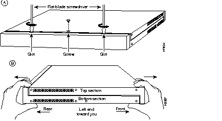
You must remove the chassis cover to access the internal power supply. When opening the chassis, refer to Parts A and B in Figure 1.
Warning 
Before working on equipment that is connected to power lines, remove jewelry (including rings, necklaces, and watches). Metal objects will heat up when connected to power and ground and can cause serious burns or weld the metal object to the terminals. (To see translated versions of this warning, refer to the Regulatory Compliance and Safety Information document that accompanied the router.)
Warning 
Before working on a chassis or working near power supplies, unplug the power cord on AC units; disconnect the power at the circuit breaker on DC units. (To see translated versions of this warning, refer to the Regulatory Compliance and Safety Information document that accompanied the router.)
Warning 
Do not work on the system or connect or disconnect cables during periods of lightning activity. (To see translated versions of this warning, refer to the Regulatory Compliance and Safety Information document that accompanied the router.)
Take the following steps to remove the chassis cover:
Step 1 Power OFF the router.
Step 2 Attach your ESD-preventive wrist strap.
Step 3 Disconnect all cables from the rear panel of the router.
Step 4 Turn the unit upside down so that the top of the chassis is resting on a flat surface, and the front of the chassis is facing toward you. (See Figure 1, Part A.)
Step 5 Remove the single screw located on the bottom of the chassis (on the side closest to you). Note that the chassis is comprised of two sections: top and bottom.
Step 6 If required, insert a medium-size flat-blade screwdriver into the slots shown in Figure 1, Part A, and rotate the blade so that the top and bottom sections separate slightly.
Step 7 Holding the chassis with both hands, position it as shown in Figure 1, Part B.
Step 8 Pull the top section away from the bottom section. (See Figure 1, Part B.) The fit is very snug, so it may be necessary to pry the chassis sections apart at one end and then the other until they separate.
This section describes how to remove an AC or DC power supply. Although an AC power supply is shown in the illustrations that follow, the procedure is the same for removing both AC and DC power supplies.
Take the following steps to remove a power supply:
Step 1 Remove the screw located between the power switch and power connector.
(See Figure 2.) This screw secures the power supply to the chassis.

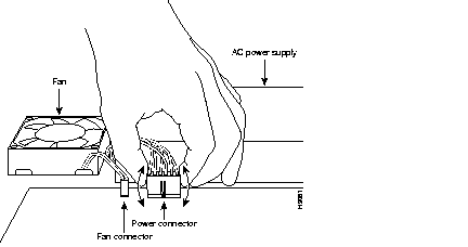
Step 2 Disconnect the power connector from the system board. (See Figure 3.) Grasp the sides of the power connector and pull upward while rocking the connector side to side.
 | Caution Do not pull on the connector wires. |
Step 3 Push the loosened power supply backward and lift it out of the chassis. (See Figure 4.)

Step 4 Place the removed screw and power supply in an antistatic bag.
This section describes how to install AC and DC power supplies. Although an AC power supply is shown in the illustrations that follow, the procedure is the same for installing both AC and DC power supplies.
Step 1 Put the power supply into place and gently slide it toward the back of the chassis engaging the tabs on the bottom of the case with the slots in the bottom of the power supply.
(See Figure 5.)
Step 2 Install the screw that came with the Cisco power supply into the screw hole between the power switch and power connector. (See Figure 6.)

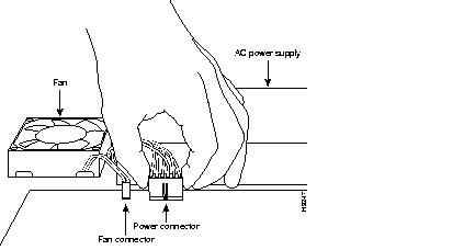
Step 3 Connect the power connector from the system board. Grasp the sides of the power connector and gently push downward while rocking the connector side to side.
(See Figure 7.)
Take the following steps to replace the cover:
Step 1 Position the two chassis sections, as shown in Figure 8.
Step 2 Referring to Figure 8, press the two chassis sections together and ensure the following:

Step 3 When the two sections fit together snugly, turn the chassis so that the bottom is facing up, with the front panel toward you.
Step 4 Replace the cover screw. (See Figure 8.)
Step 5 Remove the protective cover from the back of the power requirements label.
Step 6 Carefully place the label directly over the silk screened power requirements information on the rear panel of the system.
Step 7 Remove the protective cover from the back of the system designation label.
Step 8 Carefully place the label directly over the silk screened system designation information on the rear panel of the system.
Step 9 Reinstall the chassis on the wall, rack, desktop, or table.
Step 10 Replace all cables.
Step 11 Remove your ESD-preventive wrist strap.
This completes the procedure for installing AC and DC power supplies. If you have questions or need assistance, see the section "Obtaining Service and Support."
This section describes the DC power supply specifications and wiring.
The DC power supply is intended for use in DC operating environments. Table 1 lists the power supply specifications.
| Description | Design Specification |
|---|---|
| Power (input) | 40W, -40 to -72 VDC |
| Wire gauge for power connections | 14 AWG1 |
Follow the directions in this section to wire the terminal block.
Take the following steps to wire the terminal block:
Step 1 Attach the appropriate lugs at the wire end of the power supply cord.
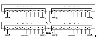
Step 2 Wire the DC power supply to the terminal block, as shown in Figure 9.

 | Caution Do not overtorque the terminal block captive thumbscrew or terminal block contact screws. The recommended torque is 8.2 ± 0.4 inch-lb. |
Warning 
This product relies on the building's installation for short-circuit (overcurrent) protection. Ensure that a fuse or circuit breaker no larger than 120 VAC, 15A U.S. (240 VAC, 10A international) is used on the phase conductors (all current-carrying conductors). (To see translated versions of this warning, refer to the Regulatory Compliance and Safety Information document that accompanied the router.)
Warning 
This equipment is intended to be grounded. Ensure that the host is connected to earth ground during normal use. (To see translated versions of this warning, refer to the Regulatory Compliance and Safety Information document that accompanied the router.)
Follow the directions in this section to place the Power Requirements and System Identifier labels on the rear panel of the Cisco 2500 series routers.
Step 1 Remove the Power Requirements label from the sheet of labels included with the power supply. (See Figure 10.)

Step 2 Place the label directly over the silk screened power requirements on the rear panel of the Cisco 2500 series router. (See Figure 11)
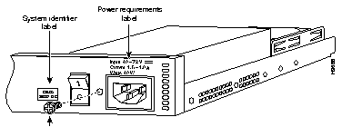
Step 3 Remove the System Identifier label from the sheet of labels included with the power supply. (See Figure 10)
Step 4 Place the System Identifier label directly to the left of the on/off power switch on the rear panel of the Cisco 2500 series router. (See Figure 11)
For service and support for a product purchased from a reseller, contact the reseller. Resellers offer a wide variety of Cisco service and support programs, which are described in the section "Service and Support" in the information packet that shipped with your chassis.
For service and support for a product purchased directly from Cisco, use CCO.
CCO is Cisco Systems' primary, real-time support channel. SMARTnet customers and partners can self-register on CCO to obtain additional information and services.
Available 24 hours a day, 7 days a week, CCO provides a wealth of standard and value-added services to Cisco's customers and business partners. CCO services include product information, product documentation, software updates, release notes, technical tips, the Bug Navigator, configuration notes, brochures, descriptions of service offerings, and download access to public and authorized files.
CCO serves a wide variety of users through two interfaces that are updated and enhanced simultaneously: a character-based version and a multimedia version that resides on the World Wide Web (WWW). The character-based CCO supports Zmodem, Kermit, Xmodem, FTP, and Internet e-mail, and it is excellent for quick access to information over lower bandwidths. The WWW version of CCO provides richly formatted documents with photographs, figures, graphics, and video, as well as hyperlinks to related information.
You can access CCO in the following ways:
For a copy of CCO's Frequently Asked Questions (FAQ), contact cco-help@cisco.com. For additional information, contact cco-team@cisco.com.
Please use CCO to obtain general information about Cisco Systems, Cisco products, or upgrades. If CCO is not accessible, contact 800 553-6387, 408 526-7208, or cs-rep@cisco.com.

|
|