|
|

This chapter contains information on maintenance procedures you might need to perform as your internetworking needs change.
If any upgrades requiring hardware or software replacement are necessary, a related publication called a configuration note will ship to you automatically with the parts.
This chapter contains the following sections:
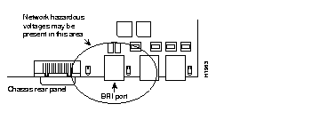
 | Warning Network hazardous voltages are accessible in the BRI cable. If you detach the BRI cable, detach the end away from the router first to avoid possible electric shock. Network hazardous voltages also are accessible on the system card in the area of the BRI port (RJ-45 connector), even when power is off. (See Figure 5-1 and Figure 5-3.) |
 | Caution Before opening the chassis, ensure that you have discharged all static electricity from your body and be sure the power is off. Before performing any procedures described in this chapter, review the sections, "Safety Recommendations," "Maintaining Safety with Electricity," "Preventing Electrostatic Discharge Damage," and "General Site Requirements" in the chapter, "Preparing for Installation." |
This section explains how to open the chassis by removing the chassis cover.
 | Warning To prevent shock hazard and injury, do not touch the power supply and fan assemblies. These components are not user-serviceable. |
The following tools are required to open the chassis:
Refer to Parts A and B in Figure 5-2 and follow these steps to remove the chassis cover:
Step 1 Turn OFF power, but to channel ESD voltages to ground, do not unplug the power cable.
Step 2 Attach an ESD-preventative wrist strap.
Step 3 Remove all interface cables from the rear panel of the router.
 | Warning Network hazardous voltages are accessible in the BRI cable. If you detach the BRI cable, detach the end away from the router first to avoid possible electric shock. Network hazardous voltages also are accessible on the system card in the area of the BRI port (RJ-45 connector), even when power is turned OFF. (See Figure 5-1.) |
Step 4 Turn the unit upside down so that the top of the chassis is resting on a flat surface and the front of the chassis is facing you. (See Figure 5-2, Part A.)
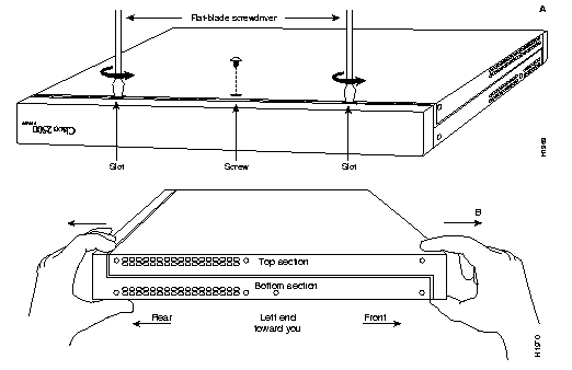
Step 5 Remove the single screw located on the bottom of the chassis (on the chassis side closest to you). Note that the chassis is comprised of two sections: top and bottom.
Step 6 If necessary, insert a medium flat-blade screwdriver into the slots shown in Figure 5-2, Part A, and gently rotate the blade so that the top and bottom sections separate slightly.
Step 7 Holding the chassis with both hands, position it as shown in Figure 5-2, Part B.
Step 8 Gently pull the top section away from the bottom section. (See Figure 5-2, Part B.) The fit is very snug. It might be necessary to work the chassis sections apart at one end and then the other until the top section is removed from the bottom section.
Step 9 When the top section is removed, set it aside. Figure 5-3 shows the layout of the system board, which is attached to the bottom section of the chassis.

Your system is equipped with either boot Flash or boot PROMs depending on the size of the boot image for the system. If the boot image is less than 1 MB, the system is equipped with Boot PROMs. If the boot image is greater than 1 MB, the system is equipped with boot Flash.
To upgrade the boot image, either replace the boot PROMs or download the boot image from a Flash memory card to the boot Flash installed on the system board. This section explains how to upgrade the boot PROMs. For information about how to download the boot image from a Flash memory card, refer to the Upgrading Boot Image with Flash Memory Cards for Cisco 2500 Series Routers publication.
Table 5-1 lists the part numbers you need to upgrade the boot PROMs and indicates their installation socket. The part number is printed on a label attached to the boot PROM.
| Boot PROM Part Number | Installation Socket |
|---|---|
| 17-1610-03 | FW 1 |
| 17-1611-03 | FW 2 |
The following tools and equipment are required to replace the boot PROMs:
Follow this procedure to replace the boot PROMs:
Step 1 To open the chassis and expose the boot PROMs, follow the procedures in the section "Opening the Chassis" earlier in this chapter.
Step 2 After the boot PROMs (FW1 and FW2) on the system card are exposed, perform Steps 3 through 6 to replace the PROMs.
Step 3 Locate the boot PROMs, FW1 and FW2 (see Figure 5-3).
Step 4 Using an PROM extraction tool or a small flat-blade screwdriver, gently remove the boot PROMs and set them aside (on a nonconductive surface).
Step 5 Insert the new boot PROMs in their respective sockets in the orientation show in Figure 5-3, being careful not to bend or crush any of the bottom pins. If you inadvertently bend a pin, use needle-nose pliers to straighten them. Align the notch in the new PROM with the notch in the PROM socket, ignoring the orientation of the label.
Step 6 Replace the tray assembly and cover following the instructions in the section "Replacing the Cover."
The router contains primary and shared memory. Primary memory stores the running configuration and routing tables. Shared memory is used for packet buffering by the router network interfaces. (See Figure Figure 5-3 for the location of primary and shared memory in your router.)
It might be necessary to expand primary memory by installing a DRAM SIMM if you are using very large routing tables or many protocols, or the router is set up as a connection device between large external networks and your internal network.
After booting your system, the system banner on the console screen displays only the amount of primary memory, in kilobytes (KB). The following example shows a system with 1 MB (1024 KB) of primary memory (shared memory is not displayed).The system does not display shared memory until later in the boot process.
System Bootstrap, Version (2.1), SOFTWARE
Copyright (c) 1986-1993 by cisco Systems
2500 processor with 1024 Kbytes of main memory
>
The router has 2 MB of fixed DRAM memory and a DRAM SIMM socket for upgrading memory. You can upgrade primary memory by installing a 4-, 8-, or 16-MB DRAM SIMM in the DRAM SIMM socket. Table 5-2 lists the upgrade amounts and corresponding memory configurations.
| Upgrade DRAM | Memory Configuration |
|---|---|
4 MB | 1 MB x 36 DRAM SIMM |
8 MB | 2 MB x 36 DRAM SIMM |
| 16 MB | 4 MB x 36 DRAM SIMM |
Order DRAM SIMMs from Cisco Systems or an approved vendor. Table 5-3 lists the upgrade amounts and corresponding Cisco Systems product numbers.
| Upgrade DRAM | Cisco Systems Product Number |
|---|---|
| 4 MB (1 MB x 36, 70 ns DRAM SIMM) | MEM1X4D=, MEM-6M= |
| 8 MB (2 MB x 36, 70 ns DRAM SIMM) | MEM-1X8D= |
| 16 MB (4 MB x 36, 70 ns DRAM SIMM) | MEM-1X16D=, MEM-18M= |
Table 5-4 lists approved 70 nanosecond (ns) DRAM SIMM vendors.
| Upgrade DRAM | Vendor | Vendor Part Number |
|---|---|---|
| 4 MB (1 MB x 36, 70 ns DRAM SIMM) | Hyundai | HYM536100AM-70 |
| Micron | MT9D136M-7 | |
| Mitsubishi | MH1M36ASDJ-7 | |
| Mitsubishi | MH1M36BNDJ-7 | |
| NEC | MC421000A36BE-70 | |
| OKI | MSC23136B-70BS12 | |
| Samsung | KMM5361003C-70 | |
| 8 MB (2 MB x 36, 70 ns DRAM SIMM) | Smart Modules | SM536C2000-7 |
| 16 MB (4 MB x 36, 70 ns DRAM SIMM) | Hitachi | HB56D436SBR-7AGS |
| Hyundai | HYM536410M-70 | |
| Mitsubishi | MH4M36ANXJ-7 | |
| NEC | MC-424000A36BE-70 | |
| Samsung | KMM5364100A-70 |
The type of memory installed, fixed DRAMs or a DRAM SIMM, effects the way shared and primary memory are allocated. Table 5-5 lists the types of memory (fixed DRAM or DRAM SIMM), how memory is allocated (as shared or primary memory), and the resulting total memory.
| Fixed DRAM Memory Installed | DRAM SIMM Memory Installed | Memory Allocated as Shared Memory | Memory Allocated as Primary Memory | Total Memory (Combined Shared and Primary Memory) |
|---|---|---|---|---|
| 0 MB | 4 MB | 2 MB | 2 MB | 4 MB |
| 0 MB | 8 MB | 2 MB | 6 MB | 8 MB |
| 0 MB | 16 MB | 2 MB | 14 MB | 16 MB |
| 2 MB | 0 MB | 1 MB | 1 MB | 2 MB |
| 2 MB | 4 MB | 2 MB | 4 MB | 6 MB |
| 2 MB | 8 MB | 2 MB | 8 MB | 10 MB |
| 2 MB | 16 MB | 2 MB | 16 MB | 18 MB |
The following tools and equipment are required:
Following is the procedure for installing DRAM SIMMs:
Step 1 Turn OFF power, but to channel ESD voltages to ground, do not unplug the power cord.
Step 2 Attach an ESD-preventive wrist strap.
Step 3 Open the cover according to the procedure in the section "Opening the Chassis."
Step 4 Turn the chassis so the system board is opposite the position shown in Figure 5-3, with the primary memory DRAM SIMM socket toward you.
Step 5 Remove the existing DRAM SIMM (if installed) by pulling outward on the connectors to unlatch them (shown in Figure 5-4). Be careful not to break the holders on the connector.
 | Caution To prevent damage, do not push on the center of the SIMM. Handle the SIMM carefully. |
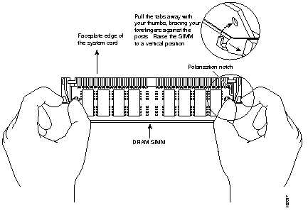
Step 6 Using the system board orientation shown in Figure 5-4, position the new SIMM so that the polarization notch is located at the right end of the SIMM socket. Note that the orientation of the system board is opposite of that shown in Figure 5-3.
Step 7 Insert the new DRAM SIMM by sliding the end with the metal fingers into the SIMM connector socket at approximately a 45-degree angle to the system card. Gently rock the SIMM back into place until the latch on either side snaps into place. Do not use excessive force, or the connector could break.
Step 8 Replace the router cover using the procedure in the section "Cover Replacement."
Step 9 Connect the router to a console terminal.
Step 10 Turn ON the power to the chassis. If error messages relating to memory are displayed, repeat Steps 1 through 7, taking care to firmly seat the SIMM in its socket.
The system code (software) is stored on Flash or PROM SIMMs. It might be necessary to upgrade the system-code SIMM if you're upgrading to a system code that is too large for the existing system-code SIMM.
The system contains two system-code SIMM slots labeled CODE0 and CODE1. You can upgrade the system-code SIMM by replacing the existing SIMM in the CODE0 slot or installing an additional SIMM in the CODE1 slot. Table 5-6 lists the SIMM slots, CODE0 and CODE1, and the proper placement of SIMMs for the desired total SIMM memory.
| SIMM Slot CODE0 | SIMM Slot CODE1 | Total SIMM Memory |
|---|---|---|
| 4 MB | 0 MB | 4 MB |
| 4 MB | 4 MB | 8 MB |
| 8 MB | 0 MB | 8 MB |
| 8 MB | 8 MB | 16 MB |
The 80-pin Flash and PROM SIMMs must be purchased from Cisco Systems. Contact a customer service representative for more information.
Following is the procedure for upgrading the system-code Flash SIMMs:
Step 1 Turn off power, but to channel ESD voltages to ground, do not unplug the power cord.
Step 2 Attach an ESD-preventive wrist strap.
Step 3 Open the chassis cover using the tools and procedures in the section "Opening the Chassis."
Step 4 Turn the chassis so that the system board is opposite the position shown in Figure 5-3, with the system-code SIMMs toward you.
Step 5 Locate the system-code SIMMs on the system board. The SIMM sockets are labeled
CODE 0 and CODE 1 (shown in Figure 5-3).
Step 6 Remove the existing system-code SIMM by pulling outward on the connectors to unlatch them. The connector holds the SIMM tightly, so be careful not to break the holders on the SIMM connector. (See Figure 5-5.)
 | Caution To prevent damage, do not push on the center of the SIMMs. Handle each SIMM carefully. |
Step 7 Repeat this procedure for all the system-code SIMMs to be replaced.
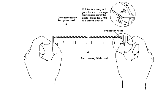
Step 8 Using the system board orientation shown in Figure 5-5, position the new SIMM so that the polarization notch is located at the right end of the SIMM socket. Note that the orientation of the system board is opposite of that shown in Figure 5-3.
Step 9 Insert the new SIMM by sliding the end with the metal fingers into the appropriate SIMM connector socket (CODE 0 or CODE 1) at approximately a 45-degree angle to the system card. Gently rock the SIMM back into place until the latch on either side snaps into place. Do not use excessive force because the connector could break.
Step 10 Replace the router cover using the procedure in the section "Replacing the Cover."
Step 11 Connect the router to a console terminal.
Step 12 Turn on the power to the chassis.
If error messages relating to memory display, repeat Steps 1 through 9, taking care to firmly seat the SIMM in the socket.
The 2500 series router provides a Flash (PCMCIA) card slot permitting the upgrade of the feature set on your 2500 series router. The available feature sets are:
Flash card feature upgrades are available only from us. Contact a customer service representative for more information.
To upgrade the feature set using a Flash memory card, follow these steps:
Step 1 Turn off the power, but to channel ESD voltages to ground, do not unplug the power cable.
Step 2 Remove all interface cables from the rear panel of the router.
Step 3 Attach an ESD-preventive wrist strap.
Step 4 Open the chassis cover following the instructions in the section "Opening the Chassis."
Step 5 Turn the chassis so the system board is in the position shown in Figure 5-7, with the primary memory DRAM SIMM socket away from you.
Step 6 Verify that the Flash memory card is set with write protection off. The write protect switch is located on the top edge of the card when oriented with the printing side up (see Figure 5-6).
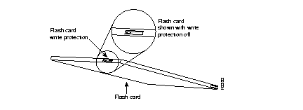
Step 7 Locate the Flash memory card socket at the upper left corner of the system board, and insert the card into the socket (see Figure 5-7).

Step 8 Reconnect the system console to the unit.
Step 9 Turn the power switch to the ON position. The system automatically starts the upgrade procedure. The upgrade screen will display on the system console (see Figure 5-8).

Step 10 Enter "Y" when the upgrade screen displays the following message:
The following message appears on the screen:
When the upgrade is complete the following message appears on the console screen:
Step 11 Turn the power switch to the OFF position and then remove the Flash memory card from its socket.
Step 12 Remove your ESD-preventive wrist strap and replace the router cover using the procedure in the section "Replacing the Cover."
Following is the procedure for replacing the cover.
Following are the tools required for replacing the cover:
After you perform the maintenance for your system, replace the cover by following these steps:
Step 1 Position the two chassis sections as shown in Figure 5-9.
Step 2 Referring to Figure 5-9, press the two chassis sections together and ensure the following:
 | Caution To fit the two sections together, it may be necessary to work them together at one end and then the other, working back and forth; however, use care to prevent bending of the chassis edges. |

Step 3 When the two sections fit together snugly, turn the chassis so that the bottom is facing up, with the front panel toward you.
Step 4 Replace the cover screw. Tighten the screw to no more than 8 or 9 inch/pounds of torque.
Step 5 Reinstall the chassis on the wall, rack, desktop, or table.
Step 6 Replace all cables.
To recover a lost password, follow these steps:
Step 1 Attach an ASCII terminal to the router console port, which is located on the rear panel.
Step 2 Configure the terminal to operate at 9600 baud, 8 data bits, no parity, 2 stop bits.
Step 3 Enter the command show version to display the existing configuration register value. Note this value for later use in Step 13.
Step 4 If Break is disabled, power cycle the router. (Turn the router off, wait 5 seconds, and then turn it on again.) If Break is enabled on the router, send a Break and then proceed to Step 5.
Step 5 Within 60 seconds of turning on the router, press the Break key. This action causes the terminal to display the bootstrap program prompt (>).
Step 6 To reset the configuration register to boot from the boot ROMs and ignore NVRAM, enter o/r at the bootstrap prompt as follows:
o/r 0x041
Step 7 Initialize the router by entering the i command as follows:
i
The router will power cycle; the configuration register will be set to 0x141 (ignore break; ignore NVRAM; boot from ROM); and the router will boot the boot ROM system image and prompt you with the system configuration dialog as follows:
Step 8 Enter no in response to the system configuration dialog prompts until the following system message appears:
Step 9 Press Return. The boot ROM prompt appears as follows:
Step 10 Enter the enable command to enter the EXEC mode in the boot ROM image. The prompt changes to the following:
Step 11 Enter the show configuration EXEC command to display the enable password in the configuration file and to display any boot system commands.
Step 12 Exit configuration mode by entering Ctrl-Z.
Step 13 Reboot the router and enable using the recovered password.
|
|