|
|

This chapter guides you through the installation of the Cisco 2500 series access server and includes the following sections:
Following are the tools and parts required to install the access server:
In addition, you might need the following external equipment:
This section explains how to install the rubber feet on the bottom of the chassis. If you want to rack-mount the chassis, skip this section and proceed with the next section, "Rack-Mounting the Chassis." To wall-mount the chassis, skip this section and proceed with the section "Wall-Mounting the Chassis" later in this chapter.
Before placing the access server on a desktop, shelf, or other flat, secure surface, perform the following steps to install the rubber feet:
Step 1 Locate the rubber feet on the black adhesive strip that shipped with the chassis. (See Figure 3-1.)

Step 2 Place the access server upside down on a smooth, flat surface.
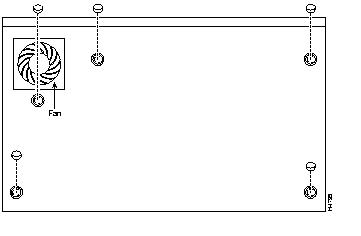
Step 3 Peel off one of the rubber feet from the black adhesive strip and place it adhesive-side down onto one of the five round recessed areas on the back of the chassis, as shown in Figure 3-2. Repeat this step to install the remaining four feet.

Depending on the rack you are using, attach the rack-mount brackets to the chassis using one of the following figures as a guide:
To install the chassis in a 19-inch rack with the front panel forward, attach the rack-mount brackets as shown in Figure 3-3.

To install the chassis in a 19-inch rack with the rear panel forward, attach the rack-mount brackets as shown in Figure 3-4.

To install the chassis in a 19-inch, center-mount telco rack, attach the rack-mount brackets as shown in Figure 3-5.

Using the screws you provide, attach the chassis assemblies to the rack as shown in Figure 3-6.

Following is the procedure for wall-mounting the chassis:
Step 1 Attach the brackets as shown in Figure 3-7.

Step 2 Using screws and anchors you provide, attach the chassis assembly to the wall as shown in Figure 3-8. We recommend the following:
 | Caution To prevent the chassis from pulling away from the wall when cables are attached, align the brackets and screws with a vertical wall stud. (See Figure 3-8.) To ensure adequate ventilation, make sure there is clearance between the access server and the wall by adjusting the brackets on the access server. Mount the access server as shown in Figure 3-8, placing the chassis fan and power supply at the top. |

Take the following steps to connect the access server to your networks:
Step 1 Connect the Ethernet or Token Ring port to the transceiver or MAU as shown in Figure 3-9 or Figure 3-10.


Step 2 Connect the synchronous serial ports to the modem or CSU/DSU, as shown in Figure 3-11. Make certain to connect the 60-pin serial port connector as shown.

Step 3 Connect the asynchronous breakout cable to one of the 68-pin ports, and then use the RJ-45-to-DB-25 adapters to connect the breakout cable and your asynchronous devices. (See Figure 3-12.)
For additional instructions on connecting asynchronous devices to the breakout cable, refer to the appendix "Cable Specifications."

 | Caution Make sure that the 68-pin connector on the breakout cable is securely connected to the access server. A short could occur which might damage the access server if the connection is disconnected. |
Step 4 Using an M 3.5 thread-forming screw (not included), attach a ground wire to the protective grounding terminal on the rear panel of the chassis, as required by your installation.
Step 5 Connect the power cable between the access server and the AC source.
The console terminal is used to provide local administrative access to the access server. Connect the terminal to the console port. The auxiliary port can be used for with a terminal, or with a modem for remote access.
This section explains how to connect a terminal (an ASCII terminal, or a PC running terminal emulation software) to the console port on the access server:
Step 1 Connect a terminal to the console port using a roll-over RJ-45 cable and an RJ-45-to-DB-25 adapter. If you are using the cable provided by Cisco, the adapter will be labeled "Terminal."
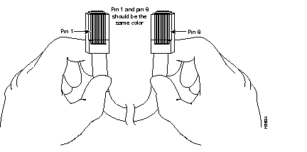
A roll-over cable can be detected by comparing the two modular ends of the cable. Holding the cables in your hand, side-by-side, with the tab at the back, the wire connected to the pin on the outside of the left plug should be the same color as the pin on the outside of the right plug. (See Figure 3-13.) If your cable was purchased from Cisco, pin 1 will be white on one connector, and pin 8 will be white on the other (a rollover cable reverses pins 1 and 8, 2 and 7, 3 and 6, and 4 and 5).

Additional information on roll-over cable pinouts is available in the appendix "Cable Specifications."
Connection to a terminal will require an RJ-45-to-DB-25 adapter, and possibly a DB-25-to-DB9 adapter. (See Figure 3-14.)

Step 2 Your terminal or PC terminal emulation software should be configured for 9600 baud, 8 data bits, no parity, and 2 stop bits (9600, 8/N/2).
This section explains how to connect a modem to the console port on the access server:
Step 1 Connect a modem to the auxiliary port using a roll-over RJ-45 cable with an RJ-45-to-DB-25 adapter. The adapter provided by Cisco will be labeled "Modem." (See Figure 3-15.)

Step 2 To configure the auxiliary port for modem operation, see the section "Modems" in the appendix "Internetworking Primer." Make sure that the modems and the auxiliary port are configured for the same transmission speed (38400 baud is normal) and hardware flow control with standard DCD and DTR operations.
After you install the access server hardware, the system is ready to be powered on and configured. For information on software configuration, refer to the chapter "Configuring the Cisco 2500 Series Access Server."
|
|