|
|

This appendix describes how to replace or upgrade memory in a Cisco 4000 series router and contains the following sections:
There are two dynamic random-access memory (DRAM) systems in Cisco 4000 series routers. One is the shared memory, which is the interface that the network processor modules send data to or transmit data from, and the other is the primary or main memory, which is reserved for the CPU. In addition, the Cisco 4000-M has Flash memory for storing the system software image; the Cisco 4500-M and Cisco 4700-M have Flash memory for the system software image and for the boot helper image.
 | Caution To avoid damaging ESD-sensitive components, observe all ESD precautions. To avoid damaging the underlying system card, avoid using excessive force when you remove or replace SIMMs. |
The Cisco 4000-M main memory upgrade requires replacing the main memory configuration of 4 MB (one 4-MB SIMM) with one 8, 16, or 32-MB SIMM. The Cisco 4500-M main memory upgrade requires replacing the main memory configuration of 8 MB (two 4-MB SIMMs) with two 8-MB SIMMs or two 16-MB SIMMs. The Cisco 4700-M main memory upgrade requires replacing the main memory configuration of two 8-MB SIMMs(16 MB) with two 16-MB SIMMs (32 MB) or with two 32-MB SIMMs (64 MB).
For the Cisco 4000-M shared-memory upgrade, replace the 4-MB shared-memory SIMM with a 16-MB shared-memory SIMM. The Cisco 4500-M and Cisco 4700-M shared-memory upgrade permits you to replace the 4-MB shared-memory SIMM with an 8-MB SIMM or a 16-MB SIMM.
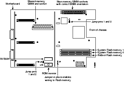
To upgrade the Cisco 4000-M Flash memory, replace the standard Flash memory configuration of 2 MB with 4 MB of Flash memory. The Cisco 4500-M and Cisco 4700-M Flash memory upgrade requires replacing or adding to the standard Flash memory configuration of 4 MB with 8, 16, 32, or 64 MB of Flash memory. Figure C-1 shows the SIMM locations in the Cisco 4000-M.
The Cisco 4000 and the Cisco 4000-M use boot ROMs to store the boot helper Cisco IOS image. To upgrade the boot ROM software to a new software image in the Cisco 4000 or Cisco 4000-M, the existing boot ROMs must be replaced.
NVRAM in the Cisco 4000 series uses an internal lithium battery to maintain data. Although this is not a field-serviceable component, we are required to provide the following safety warning:
 | Warning There is the danger of explosion if the battery is replaced incorrectly. Replace the battery only with the same or equivalent type recommended by the manufacturer. Dispose of used batteries according to the manufacturer's instructions. (To see translated versions of this warning, refer to the appendix "Translated Safety Warnings.") |

Figure C-2 shows the Cisco 4500-M and Cisco 4700-M SIMM and jumper locations.
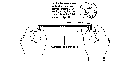
SIMMs are manufactured with a polarization notch to prevent them from being installed backward. Figure C-3 shows the polarization notch and locations of the alignment holes on a main memory SIMM card. The main memory SIMM cards are installed with the connector edge down and the component side facing in, as shown in the upper right of Figure C-1 and Figure C-2.

Take the following steps to remove main memory SIMMs:
Step 1 Put on an ESD-preventive wrist strap and ensure that it makes good contact with your skin. Connect the equipment end of the wrist strap to the metal back plate of the chassis, avoiding contact with the connectors.
Step 2 On the motherboard, locate the main memory SIMM card sockets shown in the upper right corner of Figure C-1 (for the Cisco 4000-M) and Figure C-2 (for the Cisco 4500-M and Cisco 4700-M).
 | Caution Handle SIMMs by the card edges only. SIMMs are ESD-sensitive components and can be damaged by mishandling. |
Step 3 Remove one SIMM at a time, beginning with the SIMM farthest from the edge of the motherboard. (The Cisco 4000-M has only one main memory SIMM.)
Step 4 Pull the locking spring clips on both sides outward and tilt the SIMM free of the clips to lift the SIMM out of its socket. (See Figure C-4.)
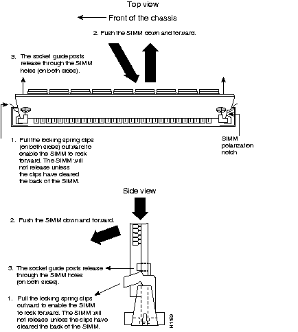
Step 5 Hold the SIMM by the edges with your thumb and index finger and lift it out of the socket. Place the removed SIMM in an antistatic bag to protect it from ESD damage.
Step 6 Repeat Step 2 through Step 5 for each main memory SIMM card.
Proceed to the next section, "Installing Main Memory SIMMs."
Take the following steps to install main memory SIMMs:
Step 1 Put on an ESD-preventive wrist strap and ensure that it makes good contact with your skin. Connect the equipment end of the wrist strap to the metal back plate of the chassis, avoiding contact with the connectors.
Step 2 On the motherboard, locate the main memory SIMM card sockets shown in the upper right corner of Figure C-1 for the Cisco 4000-M and Figure C-2 for the Cisco 4500-M and Cisco 4700-M. All of the sockets should be empty. If not, follow the steps in the section "Removing Main Memory SIMMS" earlier in this chapter.
 | Caution Handle SIMMs by the card edges only. SIMMs are ESD-sensitive components and can be damaged by mishandling. |
Step 3 Hold the SIMM with the polarization notch on the right and the component side away from you with the connector edge at the bottom. (See Figure C-3.)
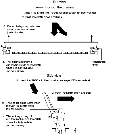
Step 4 Beginning with the SIMM nearest the edge of the motherboard, insert the main memory SIMM card at a 45-degree angle and rock it into its vertical position (see Figure C-5), using the minimum amount of force required. When the SIMM is properly seated, the socket guide posts will insert through the alignment holes, and the connector springs will click into place.
Step 5 Ensure that each SIMM is straight and that the alignment holes (as shown in Figure C-5) line up with the plastic socket guides on the socket.
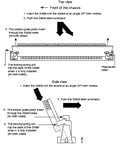
 | Caution You will feel some resistance, but do not use excessive force on the SIMM and do not touch the surface components to avoid damaging them. |
Step 6 Repeat Step 2 through Step 5 for each main memory SIMM.
If you are done with all SIMM replacement procedures, proceed to the section "Replacing Network Processor Modules" in the chapter "Configuring the Cisco 4000 Series Chassis."
Use the following procedures to replace shared-memory SIMMs in a Cisco 4000-M, Cisco 4500-M, or Cisco 4700-M.
Take the following steps to remove the shared-memory SIMMs:
Step 1 Unplug the chassis power cord and network connections.
Step 2 Put on an ESD-preventive wrist strap and ensure that it makes good contact with your skin. Connect the equipment end of the wrist strap to the metal back plate of the chassis, avoiding contact with the connectors.
Step 3 Remove the chassis cover as described in the section "Accessing the Internal Components of the Router" in the chapter "Configuring the Cisco 4000 Series Chassis."
Step 4 Remove and safely store all the network processor modules present as described in the "Replacing Network Processor Modules" section in the chapter "Configuring the Cisco 4000 Series Chassis."
Step 5 Locate the shared-memory SIMM card socket shown on the left of the motherboard as shown in Figure C-1 (for the Cisco 4000-M) and Figure C-2 (for the Cisco 4500-M and Cisco 4700-M).
Step 6 Turn the chassis so that the rear of the chassis is closest to you.
Step 7 The SIMMs are held in place at each end by small metal spring clasps. To remove a shared memory SIMM, push the two metal clasps apart. Angle the SIMM upward and pull it out. (See Figure C-5.)
 | Caution Do not exert pressure on the components on the SIMM surface because it might damage them. The sides of the SIMM must clear the metal clasps before the SIMM can be safely removed. |
Step 8 Place the removed SIMM in an antistatic bag to protect it from ESD damage.
Step 9 Repeat Step 7 and Step 8 for each SIMM.
Step 10 Proceed to the next section, "Installing Shared-Memory SIMMs."
Take the following steps to install shared-memory SIMMs:
Step 1 Unplug the chassis power cord and network connections.
Step 2 Put on an ESD-preventive wrist strap and ensure that it makes good contact with your skin. Connect the equipment end of the wrist strap to the metal back plate of the chassis, avoiding contact with the connectors.
Step 3 Remove the chassis cover as described in the section "Accessing the Internal Components of the Router" in the chapter "Configuring the Cisco 4000 Series Chassis."
Step 4 Find the shared-memory SIMM card socket locations on the left of the motherboard (as aligned in Figure C-1 and Figure C-2). All the sockets should be empty. If not, remove the shared-memory SIMMs following the procedures in the previous section "Removing Shared-Memory SIMMs."
Step 5 Turn the chassis so that the side with the shared-memory SIMM cards is closest to you.
Step 6 Hold the SIMM with the connector edge at the bottom, with the component side facing you, and the polarization notch on the left. (See Figure C-6.)
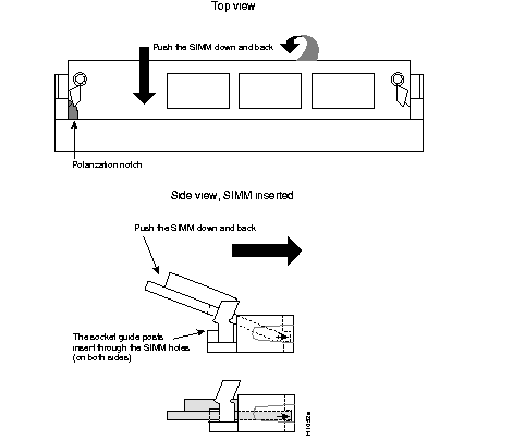
 | Caution Handle SIMMs by the card edges only. SIMMs are sensitive components and can be shorted by mishandling. |
Step 7 To insert a SIMM, angle it into position, then carefully push down and back on the edges, holding each edge so that it securely snaps into place. (See Figure C-6.) When it snaps into place, the two metal holders clip over the edge of the SIMM, and it sits horizontally.
 | Caution Avoid damage to the SIMMs and SIMM socket by handling them gently. The SIMMs are also sensitive to ESD damage. |
Step 8 Check that the SIMM is straight and that the holes are aligned with the socket guide posts on the socket. (See Figure C-6.)
If you are done with all SIMM replacement procedures, proceed to the section "Replacing Network Processor Modules" in the chapter "Configuring the Cisco 4000 Series Chassis."
The boot helper image (Rxboot image) is stored in Flash memory on the Cisco 4500-M and Cisco 4700-M. (See Figure C-7.)
You upgrade boot helper Flash memory by replacing the existing SIMM (labeled SYSTEM FLASH MEMORY 0), or by adding a second SIMM to the empty socket (labeled SYSTEM FLASH MEMORY 1).
Take the following steps to remove the boot helper Flash memory SIMM in a Cisco 4500-M or Cisco 4700-M:
Step 1 Put on an ESD-preventive wrist strap and ensure that it makes good contact with your skin. Connect the equipment end of the wrist strap to the metal back plate of the chassis, avoiding contact with the connectors.
Step 2 Locate the SIMM card socket labeled RxBoot Flash memory on the lower right corner of the Cisco 4500-M and Cisco 4700-M motherboard. (See Figure C-2.)
 | Caution Handle SIMMs by the card edges only. SIMMs are ESD-sensitive components and can be damaged by mishandling. |
Step 3 Pull the locking spring clips on both sides outward and tilt the SIMM free of the clips to lift the SIMM out of its socket. (See Figure C-7.)
Proceed to the next section, "Installing Flash-Memory SIMMs."
Take the following steps to add Flash memory SIMMs:
Step 1 On the motherboard, locate the Flash-memory SIMM sockets shown in Figure C-1 and Figure C-2.
 | Caution Handle SIMMs by the edges only. SIMMs are ESD-sensitive components and can be damaged by mishandling. |
Step 2 Hold the SIMM with the polarization notch on the right and the component side away from you with the connector edge at the bottom.
Step 3 Referring to Figure C-8, insert the Flash-memory SIMM at a 45-degree angle and rock it into its vertical position. (See Figure C-1 and Figure C-2.) When the SIMM is properly seated, the socket guide posts will insert through the alignment holes, and the locking springs will click into place. Use the minimum amount of force required.
 | Caution You will feel some resistance, but do not use excessive force on the SIMM and do not touch the surface components to avoid damaging them. |
Step 4 Check the alignment of each SIMM to make sure that it is straight and that the alignment holes are lined up with the plastic socket guides.
If you have completed all memory upgrade procedures, proceed to the section "Replacing Network Processor Modules" in the chapter "Configuring the Cisco 4000 Series Chassis."
To upgrade the boot read-only memory (ROM) software to a new software image, the existing boot ROMs must be replaced.
Take the following steps to replace boot ROMs in a Cisco 4000-M.
Step 1 Remove the chassis cover and expose the boot ROMs following the procedures in the section "Accessing the Internal Components of the Router" in the chapter "Configuring the Cisco 4000 Series Chassis."
Step 2 After the boot ROMs labeled FW1 and FW2 on the system card are exposed (see Figure C-1), follow the procedures in this section to replace the boot ROMs.
Step 3 Locate the boot ROMs, FW1 and FW2, on the motherboard. (See Figure C-9.)
Step 4 Gently extract the old ROMs with an ROM extraction tool or a small flat-blade screwdriver, and set the old boot ROMs aside.
Step 5 Insert the new boot ROMs in their respective sockets in the orientation shown in Figure C-9, being careful not to bend or crush any of the bottom pins. To straighten out a bent pin, use needlenose pliers. Align the notch in the new ROM with the notch in the ROM socket, ignoring the orientation of the label.

Step 6 Jumpers J7 and J8 must be set to designate the capacity of the Boot ROMs. For the 8 MB boot ROMs used in Cisco IOS Release 10.2(8) and higher, short pins 2 and 3 on jumper J7 and on jumper J8. (See Figure C-9.) For the 4 MB boot ROMs used in Cisco IOS releases prior to version 10.2(8), short pins 2 and 3 on jumper J7 and pins 1 and 2 on jumper J8. (See Figure C-9.)
If you have completed all memory upgrade procedures, proceed to the section "Replacing Network Processor Modules" in the chapter "Configuring the Cisco 4000 Series Chassis."
Test your installing by rebooting the system. When you power up a system in which one or more of the boot ROMs was incorrectly inserted, the system will not boot into the ROM monitor or the operating system mode.
If you suspect that your boot ROMs were inserted incorrectly, reopen the chassis, locate the affected boot ROM and remove it, straighten its pins, reinsert the boot ROM, and try booting the system again.
 | Caution The notch on the ROM must match the notch on the socket on the card. Installing the components backward will damage them. |
|
|