|
|
The access server provides the greatest benefit for midsized organizations or service providers that need to centralize processing capabilities for mobile users and telecommuters.
The access server is optimized for high-speed modem access and is ideally suited for all traditional dial-up applications, such as access to a host, electronic mail, file transfer, and dial-in access to a LAN.
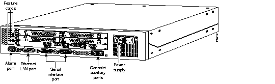
The access server consists of the following components:
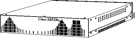
Figure 1-1 shows the front panel of the access server, and Figure 1-2 shows the rear panel.
The access server includes three slots in which you can install a combination of the following feature cards:
You can install one of the following feature cards in any of the three available slots:
In the two remaining slots, you can install carrier cards.
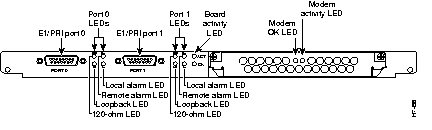
The dual T1/PRI card routes incoming digital T1 lines to the 12-port modules. The dual T1/PRI card provides RJ-48C connectors to terminate trunks. The dual T1/PRI card performs all necessary equalization and gain functions to support 6000 feet of 24-gauge unshielded cable. This card complies with all Bell Core standards relating to T1 (ANSI T1.403) alarms, loopbacks, and error detection. The dual T1/PRI card is equipped with integrated CSUs.
The dual T1/PRI card handles up to 48 digital signal level 0 (DS-0) channels from two trunks. Each channel carries either a pulse code modulation (PCM)-encoded voice channel or digital data. The dual T1/PRI card supports 64-kbps clear channel operation for data or voice channels and feature group B operation for voice channels.
Figure 1-3 shows the dual T1/PRI card.

The dual E1/PRI card is installed in the access server to provide physical termination for two E1/PRI lines. The card is designed to support the E1 cable standard of 30 Bearer (B) channels for voice and data, one Data (D) channel for signaling, and one channel for framing. Each channel transmits at up to 64 kbps for a combined total of 2.048 Mbps for each E1/PRI line.
The access server is used to service calls from users accessing remote services using a variety of network protocols. Calls are terminated in the access server through 60 modems installed on optional 12-port modules. User data can then be routed through the Ethernet or synchronous serial ports on the access server chassis.
The following list describes the features of the Dual E1/PRI card:
The dual E1/PRI card is shown in Figure 1-4.
You can install up to two carrier cards in any unpopulated slot of the access server chassis. Each carrier card includes two slots in which you can install any combination of the following 12-port modules:
The modules connect through the carrier card and the system backplane to a dual T1/PRI or dual E1/PRI card installed in the access server chassis. Data is transmitted or received on T1 or E1 lines connected to the dual T1/PRI or dual E1/PRI card and then routed to the 12-port modules installed in the carrier card.
Figure 1-5 shows the carrier card.

The access server supports the following 12-port modules:
In an access server with a dual T1/PRI card installed, you can install up to four 12-port modules for a total of 48 ports. If your access server includes a dual E1/PRI card, you can install up to five 12-port modules for a total of 60 ports. The dual E1/PRI card (see Figure 1-4) includes an extra slot for a 12-port module, which provides you with 12 extra ports to terminate up to 60 lines.
Each modem on the V.34 12-port module supports V.42bis data compression and uses the Hayes Smartmodem AT and V.25bis command sets. The Microcom Networking Protocol (MNP) and V.42 error-correction protocol standards provide error-free performance. The modem offers MNP Class 10 with Adverse Channel Enhancements (ACE). MNP 10 includes:
The V.34 module supports the following protocol and modulation standards:
Figure 1-6 shows the V.34 12-port module.
The 56K 12-port module uses Rockwell's K56Flex technology. The module can send data at up to 56 kbps and receive data at up to 33.6 kbps. Connections at 56 kbps start as analog, are converted to digital, and are not converted back to analog at the service provider. Because one conversion (from digital to analog) is omitted, speeds of up to 56 kbps are possible. However, the actual speed that you can achieve with the module depends on the condition of your local telephone network.
The 56K 12-port module supports the following protocol and modulation standards:
Figure 1-7 shows the 56K 12-port module.

The V.110 12-port module includes onboard terminal adapters (TAs) that can terminate up to 12 V.110 rate-adapted digital calls. The V.110 rate adaption protocol is used primarily for:
The V.110 12-port module includes the following features:
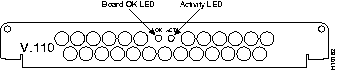
Figure 1-8 shows the V.110 12-port module.
Either an AC or DC power supply is available. The power supply provides DC power to the installed feature cards via connectors on the backplane.
The specifications of the access server are listed in Table 1-1.
| Description | Specification |
|---|---|
| Dimensions (H x W x D) | 3.5 x 17.5 x 15 in. (8.89 x 44.45 x 38.1 cm) |
| Weight | 25 lb (11.4 kg) |
| Processor | 20-MHz Motorola 68EC030 |
| Operating environment | 32 to 104×F (0 to 40×C) |
| Nonoperating temperature | -40 to 185×F (-40 to 85×C) |
| Operating humidity | 5 to 95%, noncondensing |
| Noise level | 34 dB1 @ 3 feet(0.914 m) |
| Input voltage, AC power supply Current Frequency Power dissipation | 100 to 240 VAC2 1.5 to 3.0A 50/60 Hz 180W (maximum), 135.5 Btus3 per hour |
| Input voltage, DC power supply Maximum input current Typical input current Power dissipation Output voltage 5V Output voltage 12V Output voltage -12V Protection | -48 to -60 VDC 6.0A 4.0A 180W (maximum) 5.0 VDC 26A 12.00 VDC 3A -12.00 VDC 2A Current limit, overpower |
| WAN interface options | Dual T1/PRI (RJ-48C)
Dual E1/PRI (DB-15) Five-in-one synchronous serial (DB-60) |
| LAN interface options | Ethernet AUI4 (DB-15) |
| Synchronous serial interfaces (five-in-one synchronous serial WAN ports) | EIA/TIA5-232, EIA/TIA-449, V.35, X.21 (NRZ/NRZI6 and DTE/DCE7 mode) EIA-530 (NRZ/NRZI and DTE mode) The five-in-one synchronous serial interface uses the DB-60 connector at the chassis. |
| Console and auxiliary ports | Asynchronous serial (RJ-45) |
Alarm relay rating:
|
30 VDC |
| Regulatory compliance | FCC Part 68. See also the Regulatory Compliance and Safety Information document that shipped with the access server. |
The following text is required for Federal Communications Commission (FCC) Part 68 regulatory compliance:
This equipment complies with Part 68 of the FCC rules. On the side of this Network Module interface card is a label that contains, among other information, the FCC registration number. If requested, this information must be provided to the telephone company.
If this equipment causes harm to the telephone network, the telephone company will notify you in advance that temporary discontinuance of service may be required. If advance notice is not practical, the telephone company will notify the customer as soon as possible. Also, you will be advised of your right to file a complaint with the FCC if you believe it is necessary.
The telephone company may make changes in its facilities, equipment, operations, or procedures that could affect the operation of the equipment. If this happens, the telephone company will provide advance notice for you to make the necessary modifications to maintain uninterrupted service.
If you experience any trouble with this equipment, please contact the following for repair or warranty information.
Cisco Systems, Inc.
RMA Receiving
1135 Walsh Avenue
Santa Clara, California 95050
If the trouble is causing harm to the telephone network, the telephone company may request that you remove the equipment from the network until the problem is resolved.
It is recommended that the customer install an AC surge arrestor in the AC outlet to which this device is connected. This is to avoid damaging the equipment caused by local lightning strikes and other electrical surges.
The Cisco AS52-2CT1 has the 6.0F service order cable.
The unit has the following facility interface codes: 04DU9-BN, 04DU9-DN, 04DU9-IKN, 04DU9-ISN.
|
|