|
|

This document describes how to upgrade your Cisco AS5200 access server from 24 to 30 channels for a channelized E1 line using R2 signaling. R2 signaling is an international signaling standard that is common to channelized E1 networks. Because this signaling standard is not supported by the Cisco AS5200 access server, an external E1-to-E1 converter is required. Previous to this upgrade, the converter provided an E1-to-T1 conversion and 6 channels were busied out in the conversion process, leaving only 24 channels. This upgrade enables you to use all 30 channels on each E1 line.
The upgrade procedure includes these procedures, which are described in the sections that follow:
Follow these guidelines to ensure general safety:
Safety warnings appear throughout this publication in procedures that, if performed incorrectly, may harm you. A warning symbol precedes each safety warning.
Warning 
This warning symbol means danger. You are in a situation that could cause bodily injury. Before you work on any equipment, be aware of the hazards involved with electrical circuitry and be familiar with standard practices for preventing accidents. To see translations of the warnings that appear in this publication, refer to the Regulatory Compliance and Safety Information document that accompanied this device.
Waarschuwing Dit waarschuwingssymbool betekent gevaar. U verkeert in een situatie die lichamelijk letsel kan veroorzaken. Voordat u aan enige apparatuur gaat werken, dient u zich bewust te zijn van de bij elektrische schakelingen betrokken risico's en dient u op de hoogte te zijn van standaard maatregelen om ongelukken te voorkomen. Voor vertalingen van de waarschuwingen die in deze publicatie verschijnen, kunt u het document Regulatory Compliance and Safety Information (Informatie over naleving van veiligheids- en andere voorschriften) raadplegen dat bij dit toestel is ingesloten.
Varoitus Tämä varoitusmerkki merkitsee vaaraa. Olet tilanteessa, joka voi johtaa ruumiinvammaan. Ennen kuin työskentelet minkään laitteiston parissa, ota selvää sähkökytkentöihin liittyvistä vaaroista ja tavanomaisista onnettomuuksien ehkäisykeinoista. Tässä julkaisussa esiintyvien varoitusten käännökset löydät laitteen mukana olevasta Regulatory Compliance and Safety Information -kirjasesta (määräysten noudattaminen ja tietoa turvallisuudesta).
Attention Ce symbole d'avertissement indique un danger. Vous vous trouvez dans une situation pouvant causer des blessures ou des dommages corporels. Avant de travailler sur un équipement, soyez conscient des dangers posés par les circuits électriques et familiarisez-vous avec les procédures couramment utilisées pour éviter les accidents. Pour prendre connaissance des traductions d'avertissements figurant dans cette publication, consultez le document Regulatory Compliance and Safety Information (Conformité aux règlements et consignes de sécurité) qui accompagne cet appareil.
Warnung Dieses Warnsymbol bedeutet Gefahr. Sie befinden sich in einer Situation, die zu einer Körperverletzung führen könnte. Bevor Sie mit der Arbeit an irgendeinem Gerät beginnen, seien Sie sich der mit elektrischen Stromkreisen verbundenen Gefahren und der Standardpraktiken zur Vermeidung von Unfällen bewußt. Übersetzungen der in dieser Veröffentlichung enthaltenen Warnhinweise finden Sie im Dokument Regulatory Compliance and Safety Information (Informationen zu behördlichen Vorschriften und Sicherheit), das zusammen mit diesem Gerät geliefert wurde.
Avvertenza Questo simbolo di avvertenza indica un pericolo. La situazione potrebbe causare infortuni alle persone. Prima di lavorare su qualsiasi apparecchiatura, occorre conoscere i pericoli relativi ai circuiti elettrici ed essere al corrente delle pratiche standard per la prevenzione di incidenti. La traduzione delle avvertenze riportate in questa pubblicazione si trova nel documento Regulatory Compliance and Safety Information (Conformità alle norme e informazioni sulla sicurezza) che accompagna questo dispositivo.
Advarsel Dette varselsymbolet betyr fare. Du befinner deg i en situasjon som kan føre til personskade. Før du utfører arbeid på utstyr, må du vare oppmerksom på de faremomentene som elektriske kretser innebærer, samt gjøre deg kjent med vanlig praksis når det gjelder å unngå ulykker. Hvis du vil se oversettelser av de advarslene som finnes i denne publikasjonen, kan du se i dokumentet Regulatory Compliance and Safety Information (Overholdelse av forskrifter og sikkerhetsinformasjon) som ble levert med denne enheten.
Aviso Este símbolo de aviso indica perigo. Encontra-se numa situação que lhe poderá causar danos físicos. Antes de começar a trabalhar com qualquer equipamento, familiarize-se com os perigos relacionados com circuitos eléctricos, e com quaisquer práticas comuns que possam prevenir possíveis acidentes. Para ver as traduções dos avisos que constam desta publicação, consulte o documento Regulatory Compliance and Safety Information (Informação de Segurança e Disposições Reguladoras) que acompanha este dispositivo.
¡Advertencia! Este símbolo de aviso significa peligro. Existe riesgo para su integridad física. Antes de manipular cualquier equipo, considerar los riesgos que entraña la corriente eléctrica y familiarizarse con los procedimientos estándar de prevención de accidentes. Para ver una traducción de las advertencias que aparecen en esta publicación, consultar el documento titulado Regulatory Compliance and Safety Information (Información sobre seguridad y conformidad con las disposiciones reglamentarias) que se acompaña con este dispositivo.
Varning! Denna varningssymbol signalerar fara. Du befinner dig i en situation som kan leda till personskada. Innan du utför arbete på någon utrustning måste du vara medveten om farorna med elkretsar och känna till vanligt förfarande för att förebygga skador. Se förklaringar av de varningar som förkommer i denna publikation i dokumentet Regulatory Compliance and Safety Information (Efterrättelse av föreskrifter och säkerhetsinformation), vilket medföljer denna anordning.
Follow these guidelines when working on equipment powered by electricity:
| Warning Read the installation instructions before you connect the system to its power source. |
| Warning Ultimate disposal of this product should be handled according to all national laws and regulations. |
| Warning Only trained and qualified personnel should be allowed to install or replace this equipment. |
| Warning To ensure your safety and the safety of others, be sure the power is OFF and the power cord is unplugged before working on the router. |
| Warning Before working on equipment that is connected to power lines, remove jewelry (including rings, necklaces, and watches). Metal objects will heat up when connected to power and ground and can cause serious burns or weld the metal object to the terminals. |
Electrostatic discharge (ESD) can damage equipment and impair electrical circuitry. It occurs when electronic printed circuit cards are improperly handled and can result in complete or intermittent failures. Always follow ESD prevention procedures when removing and replacing cards. Ensure that the chassis is electrically connected to earth ground. Wear an ESD-preventive wrist strap, ensuring that it makes good skin contact. Connect the clip to an unpainted surface of the chassis frame to safely channel unwanted ESD voltages to ground. To properly guard against ESD damage and shocks, the wrist strap and cord must operate effectively. If no wrist strap is available, ground yourself by touching the metal part of the chassis.
 | Caution For safety, periodically check the resistance value of the antistatic strap, which should be between 1 and 10 megohms (Mohm). |
A blank slot cover must be installed over unused slots.
This section describes how to replace the dual T1 PRI card with a dual E1 PRI card and includes the following sections:
Take these steps:
Step 1 Put on an ESD-sensitive wrist strap and attach it to a metal part of the chassis.
Step 2 Power OFF the access server.
| Caution Unlike some other Cisco access servers, the feature cards are not hot-swappable (that is, you cannot remove or install them when the power to the access server is on). Be sure to turn OFF the power to the access server before installing or removing feature cards. Failure to do so can damage the access server. |
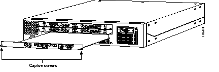
Step 3 Loosen the two captive screws on the card.
Step 4 Remove the card from the slot.
Step 5 If you have more than one Cisco AS5200 access server, repeat this procedure to remove additional dual T1 PRI cards.
Proceed to the next section, "Installing the Dual E1 PRI Card."
Take these steps:
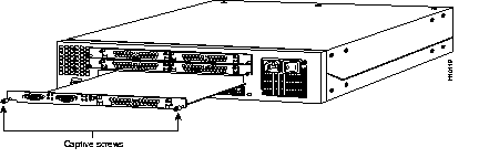
Step 1 Slide the card into the unused slot along the card guides until it is completely seated in the connector inside the access server.
Step 2 Tighten the two captive screws on the card to secure it to the chassis.
Step 3 If the access server is configured with fewer than three feature cards, make sure that a blank slot cover is installed over each open slot to ensure proper airflow inside the chassis.
Step 4 If you have more than one Cisco AS5200 access server, repeat this procedure to install additional dual E1 PRI cards.
Step 5 Remove your ESD-preventive wrist strap.
Proceed to the next section, "Replacing the TSM100 Cards in the E1-to-E1 Converter."
This section describes how to replace the T1/E1 truck signaling module (TSM100) cards with E1/E1 TSM100 cards and includes the following sections:
Take these steps:
Step 1 Put on an ESD-sensitive wrist strap and attach it to a metal part of the chassis.
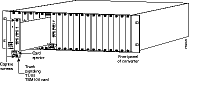
Step 2 Loosen the captive screws on the T1/E1 TSM100 card.
Step 3 Press down firmly on the small square card ejector at the bottom of the card to separate it from the connector at the back of the slot.
Step 4 Remove the card from the slot.
Step 5 Repeat this procedure to remove additional T1/E1 TSM100 cards.
Proceed to the next section, "Installing E1/E1 TSM100 Cards."
Take these steps:
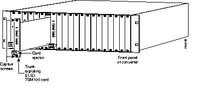
Step 1 Slide the card into the unused slot along the card guides until it is completely seated in the connector inside the converter.
Step 2 Tighten the two captive screws on the card to secure it to the chassis.
Step 3 Repeat this procedure to install additional E1/E1 TSM100 cards.
Step 4 Remove your ESD-preventive wrist strap.
Proceed to the next section, "Connecting the E1-to-E1 Converter to the Cisco AS5200 Access Server."
Take these steps:
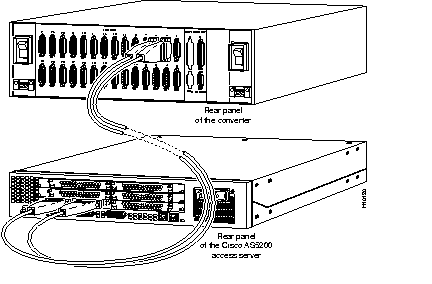
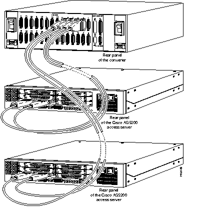
Step 1 Connect a DB-15 to DB-15 cable to the top port of the TSM100 card and one of the E1 PRI ports of the Cisco AS5200 access server. The DB-15 connectors are labeled "TO TSM100" and "TO AS5200." The connectors on both sides of the cable are male, so be sure to connect the correct end of the cable to each device.
Figure 5 shows a configuration with only one Cisco AS5200 access server. Figure 6 shows a configuration with more than one Cisco AS5200 access server.
Step 2 Repeat this procedure until all of the E1/E1 TMS100 cards are connected to the dual E1 PRI cards.
Step 3 Reconnect any cables you disconnected from the E1-to-E1 converter and then power it ON. Note that the bottom port of the E1/E1 TSM100 card connects to a Telco switch.
Step 4 Reconnect the power cable to each Cisco AS5200 access server (if you have more than one) and then power it ON.
Proceed to the next section, "Configuring the Cisco AS5200 for Channelized E1."
Take these steps:
Step 1 R2 signaling is supported in Cisco IOS Release 11.2.5P and later releases. If your Cisco AS5200 access server is running an earlier release, you must upgrade the Cisco IOS software to Release 11.2.5P or a later release before configuring the access server. Enter the show version command to determine the current software version.
Step 2 Enter controller configuration mode on the E1 0 controller:
controller E1 0
Step 3 Set the framing type:
framing frame_type
Substitute frame_type with crc4 or no-crc4. The type you enter must match your telco's.
Step 4 Set the line code type:
linecode line_type
Substitute with line_type with ami or hdb3. The type you enter must match your telco's.
Step 5 Configure one E1 line to serve as the primary (most stable) clock source line. (The other E1 line is configured as the secondary clock source line, which you will enter later in this procedure.)
clock source line primary
Step 6 Configure support for incoming and outgoing call signaling (such as on-hook and off-hook) for 30 channels:
cas-group 1 timeslots 1-31
exit
Step 7 Configure the second controller (E1 1). This configuration is identical to the one you entered for the first controller (E1 0) except that it is used as the secondary clock source line. In the following example, the framing type is crc4 and the line code type is hdb3. Enter the framing and line code types that match your telco's:
controller E1 1
framing crc4
linecode hdb3
clock source line secondary
cas-group 2 timeslots 1-31
exit
exit
Step 8 Save the configuration changes:
copy running-config startup-config
Proceed to the next section, "Configuring the E1-to-E1 Converter."
Take these steps:
Step 1 Enter the config trunk number command:
config trunk number
Step 2 When the following message displays, enter e for E1:
e
Step 3 Enable or disable TS16 CAS multiframe. The value you enter must match your telco's:
y
Step 4 Enter the frame type. Enter G732 if you entered no-crc4 on the Cisco AS5200 access server; otherwise, enter G704 (for crc4):
G704
Step 5 Set the source node clock, as shown in the following example:
no
Step 6 Enter the line code type. Enter yes if you are using hdb3 line coding; otherwise, enter no (for ami). The line code type you enter must match the line code type you entered on the Cisco AS5200 access server. An example follows:
yes
Step 7 You will need to configure the additional six channels you gained by upgrading from 24 T1 channels to 30 E1 channels. Enter the config chan command to begin configuring the additional six channels. Refer to your Anadigicom documentation for a description of the prompts.
This concludes the procedure for configuring the trunk line. Repeat this procedure to configure additional trunk lines.
Cisco Connection Online (CCO) is Cisco Systems' primary, real-time support channel. Maintenance customers and partners can self-register on CCO to obtain additional information and services.
Available 24 hours a day, 7 days a week, CCO provides a wealth of standard and value-added services to Cisco's customers and business partners. CCO services include product information, product documentation, software updates, release notes, technical tips, the Bug Navigator, configuration notes, brochures, descriptions of service offerings, and download access to public and authorized files.
CCO serves a wide variety of users through two interfaces that are updated and enhanced simultaneously: a character-based version and a multimedia version that resides on the World Wide Web (WWW). The character-based CCO supports Zmodem, Kermit, Xmodem, FTP, and Internet e-mail, and it is excellent for quick access to information over lower bandwidths. The WWW version of CCO provides richly formatted documents with photographs, figures, graphics, and video, as well as hyperlinks to related information.
You can access CCO in the following ways:
For a copy of CCO's Frequently Asked Questions (FAQ), contact cco-help@cisco.com. For additional information, contact cco-team@cisco.com.
|
|