|
|

This chapter helps you isolate problems in a LightStream 2020 multiservice ATM switch (LS2020 switch) to a single field-replaceable unit (FRU), such as a line card, blower, or power supply. Once you have identified the faulty FRU, refer to the chapter "Replacing FRUs" for instructions on removing and replacing it.
This chapter is divided into the following sections:
Read this chapter to learn how to use diagnostics and other methods to isolate faults in LS2020 enterprise ATM switches.
 | Caution Before removing any components from the chassis, read the safety instructions below. If you handle components without taking proper electrostatic discharge (ESD) precautions, you may damage the system. |
 | Warning LS2020 switches meet accepted safety standards. However, improper use can result in electrical shock, fire hazards, and personal injury. Read all of the following instructions carefully before installation and use. Note and adhere to all Cautions and Warnings. |
Static electricity can damage or degrade electronic components. Before you expose circuitry, make sure that your body, the rack, and the circuit boards are at the same ground potential to prevent damaging ESD. To connect yourself to ground, use a wrist strap connected to one of the system's grounding jacks, or to the bare metal surface of the system frame.
In addition to the ESD guidelines above, extra care should be taken to protect cards. All spare cards are shipped in reusable antistatic shielding bags. When cards are not installed in the machine, keep them in antistatic bags. Do not remove cards from their bags unless you are grounded. Do not place these bags on exposed electrical contacts, where they can cause short circuits.
Power-on self-test (POST) diagnostics are the first line of defense for identifying hardware problems. POST runs automatically on each card whenever the system or the slot is powered up or when the card is reset; it takes about 90 seconds. There are POSTs for the following components:
The POST for each line card also checks the accompanying access card.
If a card passes POST, the green RDY LED on its front bulkhead turns on. If a card fails POST, its yellow FLT LED turns on. To display POST results, use one of these commands:
In the resulting display, look at the POST line and the Application line. If the Application line says DISABLED, you may be able to correct the problem by enabling (activating) the card. See the LightStream 2020 Network Operations Guide for instructions.
If a card fails POST, review the portion of the section "General Troubleshooting " for the card in question. In most cases, you should also run the hardware diagnostics to confirm that a problem exists. (Hardware diagnostics are described briefly in the following section; the instructions for running them appear in the section "Hardware Diagnostics" later in this chapter.)
General troubleshooting tasks help you identify faults in NPs, switch cards, and line cards. These can be performed before, after, instead of, or in addition to running the diagnostic software. They are the only means of identifying faults in subsystems not covered by POST or diagnostics, such as blowers and power supplies.
Use the information in this section to help isolate faults in an LS2020 switch. This section is to be used in conjunction with the diagnostic software. Some of these procedures require you to be in the same room with the faulty system; others can be performed remotely.
If your LS2020 switch does not operate properly after you have tried the suggestions below, call your customer support representative.
Before resorting to the diagnostics or to complex troubleshooting, check simple things:
If you are bringing up a new LS2020 node, a new card, or a new kind of port for the first time, a likely source of problems is configuration. The problem may exist at either the LS2020 side or the remote side of the connection; be sure to check both configurations. Refer to the LightStream 2020 Configuration Guide for information on software configuration.
The symptoms listed below indicate problems that may require replacement of a switch card. Switch card replacement instructions appear in the chapter "Replacing FRUs."
If the NP fails to power up, check its access card at the back of the chassis. An NP requires an NP access card (NPAC); it cannot operate with any other kind of access card.
Consider replacing the NP if any of the following applies. NP replacement instructions appear in the chapter "Replacing FRUs."
If the system fails to boot, it could indicate either a problem with the NP itself, a problem with the NP's hard disk drive, or a problem with the software on the hard drive.
This section provides information on how to isolate faults in interface modules. (An interface module consists of a line card and its access card.)
The following will help you distinguish between problems in a line card and problems in an access card.
| Caution Do not swap one line card for another unless you are sure that the cards are of the same type. |
If you are having trouble bringing up an interface module, check the following:
If you are having signal quality problems with a physical interface on an access card, check the following:
The following conditions may require replacement of either a line card or its access card. Replacement instructions appear in the chapter "Replacing FRUs."
The following conditions indicate failure of a blower. See the chapter "Replacing FRUs" for replacement instructions.
| Warning The impeller inside the blower box may still be turning. Keep fingers, screwdrivers and other objects away from the perforations in the blower's housing. |
In a system with one power tray, no power will be present if the power tray is faulty. Suspect a problem with the power tray if cycling the system's power has no effect.
A system with two power trays can operate normally when only one is working; if you suspect a problem, use the CLI command show chassis powersupply. The display for a healthy dual-tray system is shown below. (In a system with only one power tray, both lines for the unused slot will read "Empty.")
cli> show chassis powersupply
Power Supply A:  Good
Power Supply A Type:  1200W AC Power Supply
Power Supply B:  Good
Power Supply B Type:  1200W AC Power Supply
cli>
If a status line for an occupied slot says anything other than Good, check the faulty power tray to see that it is properly connected. (Power tray slot A is on top; slot B is on the bottom.) If the problem persists, replace the power tray as described in the section "Replacing a Power Tray" in the chapter "Replacing FRUs."
Disk assembly problems are indicated by the following symptoms:
If a disk problem is indicated, check the disk assembly connector for bent or broken pins. To do so, remove the disk assembly as described in the section "Replacing a Disk Assembly" in the chapter "Replacing FRUs." Then examine the 64-pin male connector at the back of the slot. If any pins are bent or damaged, they are the likely source of the problem. Replace the disk assembly connector as described in the chapter "Replacing FRUs."
If the connector is in good condition, the problem may be in the disk assembly itself, or in the software on the disk. If you suspect a problem with the software, you should be able to correct it by reinstalling the software as described in the LightStream 2020 Network Operations Guide. If that does not solve the problem, or if you believe the problem lies in the hardware, see the section "Replacing a Disk Assembly" in the chapter "Replacing FRUs" for instructions on replacing the disk assembly.
Midplane problems are indicated by the following symptoms. Midplane replacement instructions appear in the section "Replacing the Midplane" of the chapter "Replacing FRUs."
cli> show tcs 1 voltage
Slot  1 Voltage:
   TCS VCC Voltage:        5.053 (Normal Range: 4.614 / 5.371)
   VCC Voltage:            5.029 (Normal Range: 4.370 / 5.615)
   SCSI Voltage:           4.833 (Normal Range: 4.614 / 5.371)
   VPP Voltage*:           0.000 (Normal Range: 11.067 / 12.858)
       *VPP Voltage Is Valid Only During FLASH Initialization
cli>
LS2020 hardware diagnostics are used to discover the location of hardware faults. You can run diagnostics on a line card or a backup NP while the rest of the system continues to operate. Only the card under test comes out of service during the diagnostics (except where you are testing an NP card in a non-redundant system, in which case the system must be taken off line).
Note that certain tests should not be run while the system is operating, and other restrictions may apply as well. See the "Test Notes " section later in this chapter for details.
You can run diagnostics either remotely over a telnet or modem connection, or locally from a console connected to the console port. However, to run diagnostics on the sole NP in a non-redundant system requires a local console or a modem.
The diagnostics reside on each NP's hard disk. Several parts of the system can be tested:
This section is divided into the following subsections:
You can access the diagnostics in three ways:
This section tells you how to use the test command in CLI to run field diagnostics on a line card in a specified slot or on a backup NP.
The first subsection below describes the switches you can use with the test command. The second subsection explains how to use the test command to test a line card, and the third tells you how to use the test command to test a backup NP.
The test command impedes normal traffic flow. If you are unsure of the potential impact of this command on your network, contact Cisco customer support.
The syntax of the CLI test command is as follows:
test <slot#> [-l -p -s -x -r -m] [-F<filename>]
where
diag_np1.aout : NP diagnostics
diag_clc1.aout: Cell line card diagnostics
diag_plc1.aout : Packet line card diagnostics
diag_ls1.aout : Low-speed line card diagnostics
diag_ms1.aout : Medium-speed line card diagnostics
If you use the test command with multiple switches, you must enter each one with its own - (minus) character and separate the switches with spaces. For example:
test 4 -p -x
test 4 -px
If you run the test command with no switches, diagnostics are loaded and run on the specified card in the background, and your CLI prompt returns so you can perform other tasks. The diagnostics complete in a minimum of 5 minutes. To display their status, enter test <slot#> -r.
This procedure explains how to use the test command in CLI to run diagnostics on a line card. CLI must be running on the system you plan to test.
Step 1 If the card you plan to test is passing traffic, warn anyone who will be affected that you are taking it out of service to run diagnostics.
Step 2 Log in to CLI.
Step 3 Enter protected mode:
protected
You will be prompted to enter the protected mode password.
Step 4 Use the set command to set the SNMP community to a community with write privileges. (If you do not know the appropriate community name for this system, contact the network administrator.) The example below gives the syntax of the command; replace write-community with a real community name.
set snmp community <write-community>
Step 5 Issue the test command. (Replace the 4 in the example below with the number of the card you want to test, and add any switches you need.)
test 4
Step 6 Wait at least 15 minutes for the diagnostics to load and run. If you used the -x switch with test, wait at least 30 minutes. Then use the following command to retrieve test results, replacing the 4 with the slot number of the card you just tested:
test 4 -r
The result indicates that the tests passed, that they failed, or (as shown above) that they are still running. In the last case, wait a few minutes for the tests to finish and enter test 4 -r again.
Step 7 If the tests passed, the card is OK--skip to the next step.
If the tests failed, replace the card; see the chapter "Replacing FRUs" for instructions. In the case of failure, you should also record the list of test numbers and error numbers displayed when you enter test -r, and return this list to the repair depot along with the failed card.
Step 8 To return a card to service after running diagnostics, use the following command:
set card <slot#> active
Step 9 Use the set command to change the SNMP community back to a read-only community. Replace read-community in the example below with the name of a read-only SNMP community.
set snmp community <read-community>
Follow the procedures in this section to use the test command in CLI to run diagnostics on a backup NP. (If you need to test a lone NP, see the procedure "Loading Manufacturing Diagnostics into a Lone NP " later in this chapter.) This task requires either a local console connected to the switch under test or a modem connection. You cannot use telnet.
The first procedure below explains how to force the active and backup NPs to switch roles; this is only necessary if the NP you want to test is currently active. The second procedure tells you how to run the diagnostics.
Step 1 Warn anyone who will be affected that you are taking the system off the network temporarily.
Step 2 If the NP you want to test is currently operating as the backup, skip to the next procedure, Testing the Backup NP. Continue with this procedure if the NP to be tested is active; the following steps explain how to force the active NP to become the backup so that you can run diagnostics.
If you are not sure which NP is primary, use the CLI command show chassis general and look for Slot of Primary NP in the resulting display.
Step 3 Establish a local console connection or a modem connection to the system under test. (See the LightStream 2020 Installation Guide for information on terminal settings and how to determine which port to use.)
Step 4 If the command line prompt you see does not contain the words TCS hub, enter '. to get a TCS hub prompt.
Step 5 At the TCS hub prompt, use the connect <slot#> command to connect to the NP you want to test. The example below assumes that you will test the NP in slot 1.
connect 1
Step 6 When you connect, you will see a login prompt. Log in as root or fldsup.
Step 7 At the prompt, enter reboot -n.
Step 8 Enter '. to return to the TCS hub.
Step 9 Go to step 3 of the next procedure.
Step 1 If you have not already done so, establish a local console connection or a modem connection to the switch under test. (See the LightStream 2020 Installation Guide for information on terminal settings and how to determine which port to use.)
Step 2 If the command line prompt you see does not contain the words TCS hub, enter '. to get a TCS hub prompt.
Step 3 At the TCS hub prompt, use connect <slot#> to connect to the NP that you do not want to test. You will use this NP, which must be active, to test the other one. The example below assumes that you are connecting to the NP in slot 2.
connect 2
Step 4 Log in and, if necessary, enter cli to start the CLI.
Step 5 Enter protected mode:
protected
You will be prompted to enter the protected mode password.
Step 6 Use the set command to set the SNMP community to a community with write privileges. (If you do not know the appropriate community name for this system, contact the network administrator.) The example below gives the syntax of the command; replace write-community with a real community name.
set snmp community <write-community>
Step 7 Issue the test <slot#> command, where slot# is 1 or 2--the number of the backup NP you are testing. If you need to add any switches to the test command, refer to the section "The test Command " for details.
test 1
Step 8 Wait at least 15 minutes for the diagnostics to load and run. If you used the -x switch with test, wait at least 30 minutes. Then use the following command to retrieve test results, replacing the 1 with the slot number of the card you just tested:
test 1 -r
The result indicates that the tests passed, that they failed, or (as shown above) that they are still running. In the last case, wait a few minutes for the tests to finish and enter test 1 -r again.
Step 9 If the tests passed, the card is OK--skip to the next step. If the tests failed, you should replace the card; see the chapter "Replacing FRUs" for instructions. (In the case of failure, you should also record the list of test numbers and error numbers displayed when you enter test -r, and return this list to the repair depot along with the failed card.)
Step 10 To return a card to service after running diagnostics, use the following command:
set card <slot#> active
Step 11 Use the set command to change the SNMP community back to a read-only community. Replace read-community in the example below with the name of a read-only SNMP community.
set snmp community <read-community>
You must use manufacturing diagnostics to test the single NP in a nonredundant system. If you wish, you can also use them to test backup NPs and line cards. With manufacturing diagnostics, you can specify which test(s) to run.
This section contains the following procedures:
After loading the diagnostics, see the section "Running Manufacturing Diagnostics " for instructions on what to do next.
This procedure explains how to load the manufacturing diagnostics into the sole NP in a nonredundant system. Note that this procedure requires the system under test to stop passing traffic. It also requires you to have a local console connection or a modem connection to the switch whose NP you are testing. You cannot use telnet or rlogin.
The commands used in the procedure are listed below, followed by the procedure itself:
Step 1 Warn anyone who will be affected that you are taking the system off the network temporarily.
Step 2 Establish a local console connection or a modem connection to the system under test. (See the LightStream 2020 Installation Guide for information on terminal settings and how to determine which console port to use.)
Step 3 If the command line prompt you see does not contain the words TCS hub, enter '. to get a TCS hub prompt.
Step 4 At the TCS hub prompt, use the connect <slot#> command to connect to the NP. In the example below, the NP is assumed to be in slot 1.
connect 1
Step 5 When you connect, you see a login prompt. Log in as root or fldsup.
Step 6 Enter reboot -n to enter the boot sequence. You will see the following display:
Step 7 Enter 6 at the prompt to escape to the bootstrap command line interpreter:
6
The following is displayed:
Step 8 At the boot prompt, enter the following command to load the diagnostic software:
(sd0b)diag/diag_np1.aout
You will see the following display:
Step 9 For instructions on executing tests in NP diagnostics, see the following section, "Running Manufacturing Diagnostics ."
Step 10 When you finish your diagnostic session, you must reset the NP. Enter '. to return to the TCS hub. Then use the command reset <slot#> to reset the NP.
You can use the manufacturing diagnostics to test backup NPs and line cards. Use the procedure in this section to load the manufacturing diagnostics, then go on to the following section, "Running Manufacturing Diagnostics ," for further instructions.
As you follow the procedure below, you will use these commands:
Step 1 If the card you plan to test is passing traffic, warn anyone who will be affected that you are taking it out of service to run diagnostics.
Step 2 Log into the node to be tested, start CLI and enter protected mode:
protected
You will be prompted to enter the protected mode password.
Step 3 Use the set command to set the SNMP community to a community with write privileges. (If you do not know the appropriate community name for this system, contact the network administrator.) The example below gives the syntax of the command; replace write-community with a real community name.
set snmp community <write-community>
Step 4 Issue the test command with the -m switch, which loads manufacturing diagnostics. Replace slot# below with a real slot number.
test <slot#> -m
You will see a display that resembles this one:
You can use the run command in any diagnostic package to run a preselected set of tests. See the section "Running Manufacturing Diagnostics " for detailed procedures on running tests.
If you need to return to CLI before completing your session with the diagnostics, you can toggle back and forth as follows: from the diagnostics, use the command ~q to get to CLI; from CLI, use connect <slot#> diagnostic to return to the diagnostics. Be sure to use the exit command to leave diagnostics when your session is finished.
For information on diagnostics commands, refer to the "Command Reference " section at the end of this chapter.
Read this section for information on running manufacturing diagnostics. The first subsection, "Running Sets of Tests ," applies to all of the test procedures that follow it.
In each of the diagnostics packages, commands are provided to run preselected sets of tests:
Use this procedure to run diagnostics on an NP card. You are assumed to have already loaded the diagnostics onto the card, as described in the preceding section "Loading Manufacturing Diagnostics ."
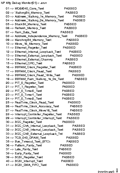
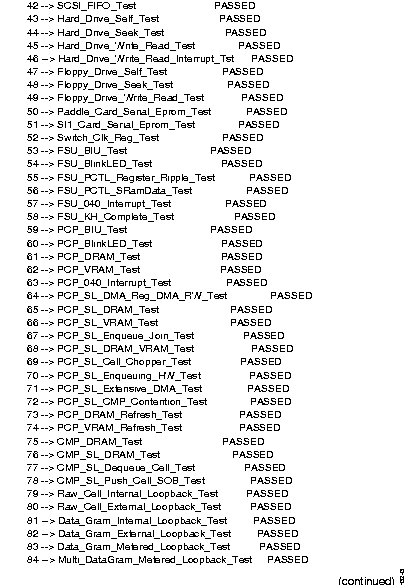
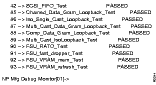
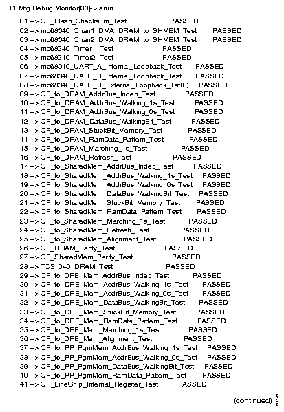
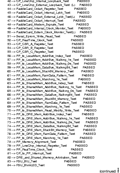
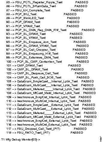
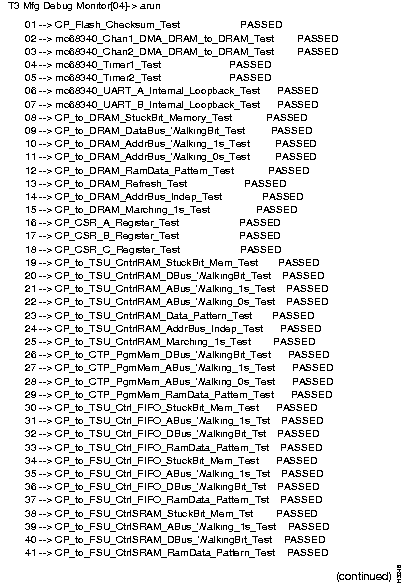
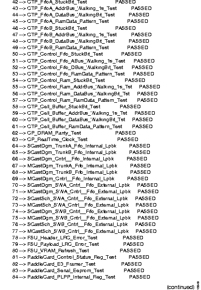
Step 1 At the prompt, enter run to run a set of tests. (See the section, "Running Sets of Tests ," for information on run.) As the tests run, the system displays the name of each test and a pass or fail indication, as shown below. (Depending on your configuration, some tests may display as "not run." This is not a problem.)
The screens that follow (Figure 2-1, Figure 2-2, and Figure 2-3) use the arun command in order to display a complete list of tests. It is recommended that you use run instead.
Step 2 To run or rerun a particular test or group of tests, you can use the run command in conjunction with test numbers. For example:
run 5-15
(To display a list of tests and test numbers, use the lst all command.)
Step 3 The status command displays a message giving the status of diagnostic tests. Use status fail to get information only on tests that have failed.
Step 4 For explanations of the error codes used in the status display, use the help command in conjunction with the number of the test in question. For example,:
help 10
Step 5 If the card passes the diagnostics, return the card to active mode. First exit from the diagnostics:
exit
'., then reset <slot#> to reset the NP, then connect <slot#> to reconnect to the NP. Replace <slot#> with the slot number of the card you were testing.
Step 6 When the login prompt appears, log in to the node, enter CLI's protected mode, and use the set command as shown below to reset the card's status to active. Replace <slot#> with the slot number of the card you were testing.
set card <slot#> active
If any tests fail, replace the card being tested. Replacement procedures appear in the chapter "Replacing FRUs."
If all tests pass but you are still experiencing a problem, test the other cards in the chassis. Consider replacing any cards that fail diagnostics. If the problem persists, investigate causes outside the LS2020 hardware, including leased lines and edge devices.
Use this procedure to run diagnostics on a low-speed line card. You are assumed to have already loaded the diagnostics onto the card, as described in the preceding section "Loading Manufacturing Diagnostics ."
Step 1 At the prompt, enter run to run a set of tests. (See the section, "Running Sets of Tests ," for information on run.) As the tests run, the system displays the name of each test and a pass or fail indication, as shown in the figure below. (Depending on your configuration, some tests may display as "not run." This is not a problem.)
Step 2 To run or rerun a particular test or group of tests, use the run command in conjunction with test numbers. For example:
run 5-15
(To display a list of tests and test numbers, use the lst all command.)
Step 3 The status command displays a message giving the status of diagnostic tests. Use status fail to get information only on tests that have failed.
Step 4 For explanations of the error codes used in the status display, use the help command in conjunction with the number of the test in question. For example,:
help 10
Step 5 If the card passes the diagnostics, return the card to active mode. First exit from the diagnostics:
exit
Step 6 When the login prompt appears, log into the node, enter CLI's protected mode, and use the set command as shown below to reset the card's status to active. Replace <slot#> with the slot number of the card you were testing.
set card <slot#> active
If any tests fail, you may need to replace either the line card being tested or its access card. (Replacement procedures appear in the chapter "Replacing FRUs.") Look at the numbers of the tests that failed to determine which card to replace:
If all tests pass but you are still experiencing a problem, test the other cards in the chassis. Consider replacing any cards that fail diagnostics. If the problem persists, investigate causes outside the LS2020 hardware, including leased lines and edge devices.
Use this procedure to run diagnostics on a medium-speed line card. You are assumed to have already loaded the diagnostics onto the card, as described in the preceding section, "Loading Manufacturing Diagnostics ."
Step 1 At the prompt, enter run to run a set of tests. (See the section, "Running Sets of Tests ," for information on run.) As the tests run, the system displays the name of each test and a pass or fail indication, as shown in the figure below. (Depending on your configuration, some tests may display as "not run." This is not a problem.)
Step 2 To run or rerun a particular test or group of tests, use the run command in conjunction with test numbers. For example:
run 5-15
(To display a list of tests and test numbers, use the lst all command.)
Step 3 The status command displays a message giving the status of diagnostic tests. Use status fail to get information only on tests that have failed.
Step 4 For explanations of the error codes used in the status display, use the help command in conjunction with the number of the test in question. For example,
help 10
Step 5 If the card passes the diagnostics, return the card to active mode. First exit from the diagnostics:
exit
Step 6 When the log in prompt appears, log into the node, enter CLI's protected mode, and use the set command as shown below to reset the card's status to active. Replace <slot#> with the slot number of the card you were testing.
set card <slot#> active
If any tests fail, you may need to replace either the line card being tested or its access card. (Replacement procedures appear in the chapter "Replacing FRUs.") Look at the numbers of the tests that failed to determine which card to replace:
If all tests pass but you are still experiencing a problem, test the other cards in the chassis. Consider replacing any cards that fail diagnostics. If the problem persists, investigate causes outside the LS2020 hardware, including leased lines and edge devices.
Use this procedure to run diagnostics on a packet line card. You are assumed to have already loaded the diagnostics onto the card, as described in the preceding section, "Loading Manufacturing Diagnostics ."
When they are loaded, the PLC diagnostics determine which type of access card is installed with the line card under test. Tests appropriate for the access card are enabled. You can use the access command, described in the section "Command Reference ," later in this chapter to display the type of the access card.
Step 1 At the prompt, enter run to run a set of tests. (See the preceding section, "Running Sets of Tests ," for information on run.) As the tests run, the system displays the name of each test and a pass or fail indication, as shown below. (Depending on your configuration, some tests may display as "not run." This is not a problem.)
run
or
or
or
or
Step 2 To run or rerun a particular test or group of tests, use the run command in conjunction with test numbers. For example:
run 5-15
(To display a list of tests and test numbers, use the lst all command.)
Step 3 The status command displays a message giving the status of diagnostic tests. Use status fail to get information only on tests that have failed.
Step 4 For explanations of the error codes used in the status display, use the help command in conjunction with the number of the test in question. For example,:
help 10
Step 5 If the card passes the diagnostics, return the card to active mode. First exit from the diagnostics:
exit
Step 6 When the login prompt appears, log in to the node, enter CLI's protected mode, and use the set command as shown below to reset the card's status to active. Replace <slot#> with the slot number of the card you were testing.
set card <slot#> active
If test 55 (or any of its subtests, 55.01 through 55.15) fails, this indicates a failure in the access card. Replace the access card, as described in the chapter "Replacing FRUs."
If any other tests fail, replace the card being tested. Replacement procedures appear in the chapter "Replacing FRUs."
If all tests pass but you are still experiencing a problem, test the other cards in the chassis. Consider replacing any cards that fail diagnostics. If the problem persists, investigate causes outside the LS2020 hardware, including leased lines and edge devices.
Use this procedure to run diagnostics on a cell line card. It assumes that you have already loaded the diagnostics onto the card, as described in the preceding section, "Loading Manufacturing Diagnostics ."
When they are loaded, the CLC diagnostics determine which type of access card is installed with the line card under test. Tests appropriate for the access card are enabled. You can use the access command, described in the section "Command Reference ," later in this chapter, to display the type of the access card.
Step 1 At the prompt, enter run to run a set of tests. (See the section, "Running Sets of Tests ," for the information on run.) As the tests run, the system displays the name of each test and a pass or fail indication, as shown below. (Depending on your configuration, some tests may display as "not run." This is not a problem.)
run
or
or
Step 2 To run or rerun a particular test or group of tests, use the run command in conjunction with test numbers. For example:
run 5-15
(To display a list of tests and test numbers, use the lst all command.)
Step 3 The status command displays a message giving the status of diagnostic tests. Use status fail to get information only on tests that have failed.
Step 4 For explanations of the error codes used in the status display, use the help command in conjunction with the number of the test in question. For example,
help 10
Step 5 If the card passes the diagnostics, return the card to active mode. First exit from the diagnostics:
exit
Step 6 When the login prompt appears, log into the node, enter CLI's protected mode, and use the set command as shown below to reset the card's status to active. Replace <slot#> with the slot number of the card you were testing.
set card <slot#> active
If test 49 (or any of its subtests) fails, this indicates a failure in the access card. In this case replace the access card, as described in the chapter "Replacing FRUs."
If any other tests fail, replace the card being tested. Replacement procedures appear in the chapter "Replacing FRUs."
If all tests pass but you are still experiencing a problem, test the other cards in the chassis. Consider replacing any cards that fail diagnostics. If the problem persists, investigate causes outside the LS2020 hardware, including leased lines and edge devices.
This section lists special requirements for tests in each diagnostic package.
The NP tests listed below write data to the hard disk. These tests are disabled by default; you must explicitly enable them in order to run them. Do not run the following tests, unless you are testing a new disk drive or have reason to suspect a fault in your hard disk.
43 -->  Hard_Drive_Self_Test
44 -->  Hard_Drive_Seek_Test
45 -->  Hard_Drive_Write_Read_Test
46 -->  Hard_Drive_Write_Read_Interrupt_Tst
The NP tests listed below send data through the switch card. Take the LS2020 node off line before running these tests, as described in the procedure below. Do not run them on a system that is passing traffic. (If the node is running, these tests may fail when they would otherwise pass. In addition, the "bad" data passed to the switch by the tests may cause traps.)
78 --> CMP_SL_Push_Cell_SOB_Test
80 --> Raw_Cell_External_Loopback_Test
82 --> Data_Gram_External_Loopback_Test
83 --> Data_Gram_Metered_Loopback_Test
84 --> Multi_DataGram_Metered_Loopback_Test
85 --> Chained_Data_Gram_Loopback_Test
86 --> Iso_Sngle_Cast_Loopback_Test
87 --> Multi_Cast_Data_Gram_Loopback_Test
88 --> Comp_Data_Gram_Loopback_Test
89 --> Multi_Cast_IsoLoopback_Test
90 --> FSU_RATO_Test
91 --> FSU_fast_dropper_Test
92 --> FSU_VRAM_mem_Test
93 --> FSU_VRAM_refresh_Test
To run these tests, use the following procedure to disable the system and all the other cards in the chassis. This prevents the other cards from sending packets to the card under test that cause these tests to fail even when no problem exists.
Step 1 Log in as root or fldsup on the system you want to test.
Step 2 At the prompt, use the command reboot -n to bring down the NP. (Bring down both if there are two.)
Step 3 Enter '. to get a TCS hub prompt.
Step 4 From the TCS hub, enter reset <slot#> to reset each slot that has a line card in it. (Do not reset the switch card or NP slots.)
Step 5 Enter connect <slot#> to return to the NP, then press Return to display a menu of boot options.
Step 6 At the menu's Option prompt, enter 6, as shown below.
6
Step 7 The system displays the following message and a boot prompt. Enter the string shown below to load the NP diagnostics.
(sd0b)diag/diag_np1.aout
Step 8 When the diagnostics finish loading, you can select and run the desired tests.
The NP tests listed below fail if they are run on a system that does not have looping plugs installed on the NP Ethernet port and Diag2 port. (In field diagnostics, these tests are invoked when you use the test command's -l switch.) If you do not have looping plugs installed, it is recommended that you avoid running these tests:
13 --> Ethernet_External_Loopback_Test
14 --> Ethernet_External_Chaining
33 --> SCC_ChB_External_Loopback_Tst
The NP tests listed below fail if they are run on a system that does not have writable diskettes in its floppy disk drives. If you do not have a scratch diskette in each floppy drive, it is recommended that you avoid running these tests:
47 -->  FLoppy_Drive_Self_Test
48 -->  Floppy_Drive_Seek_Test
49 -->  Floppy_Drive_Write_Read_Test
The NP memory tests listed below take longer than one minute to run. Some take many minutes. (In field diagnostics, these tests are invoked when you use the test command's -x switch.)
08 --> Address_Independence_Memory_Test
09 --> MarchingBit_Memory_Test
93 --> FSU_VRAM_refresh_Test
The NP diagnostics include tests for the battery-backed RAM clock that keeps time for the whole system. If the tests fail, you will be prompted to reset the clock; you must supply the current time and date. If the system under test has two NPs, their clocks must agree to within one minute or file consistency problems between the two NPs may result.
The low-speed line card tests listed below send data through the switch card. (In field diagnostics, these tests are invoked when you use the test command's -s switch.) Take the LS2020 node off line before running these tests. Do not run them on a system that is passing traffic. (If the node is running, these tests may fail when they would otherwise pass. In addition, the "bad" data passed to the switch by the tests may cause traps.)
111 --> DataGram_SingleCast__External_Lpbk_Test
112 --> DataGram_MultiCast___External_Lpbk_Test
113 --> DataGram_Metered_____External_Lpbk_Test
114 --> DataGram_MtCast_Metd_External_Lpbk_Test
115 --> Isochronous_SinglCst_External_Lpbk_Test
116 --> Isochronous_MultiCst_External_Lpbk_Test
117 --> FSU_Dropped_Cell_Test_(PIT)
118 --> FSU_RATO_Test_(PIT)
To run these tests, use the procedure below to disable the system and all the other cards in the chassis, and then to load the diagnostics into the card you wish to test. This procedure prevents the other cards from sending packets to the card under test that cause these tests to fail even when no problem exists.
Step 1 Log in as root or fldsup on the system you want to test.
Step 2 At the prompt, enter the command reboot -n to bring down the NP. If your system has two NPs, do the following to reboot the second one:
'. to get a TCS hub prompt.
Step 3 Enter '. to get a TCS hub prompt.
Step 4 From the TCS hub, enter reset <slot#> to reset each slot that has a line card in it. (Do not reset the switch card or NP slots.)
Step 5 Enter connect <slot#> to return to the NP, then press Return to display a menu of boot options.
Step 6 At the menu's Option prompt, enter 6, as shown below.
6
Step 7 The system displays the following message and a boot prompt. Enter the string shown below to load the system monitor, which you will use to load the diagnostics.
(sd0b)diag/sys_np1.aout
Step 8 When the system monitor finishes loading, you will see an identifying message and a prompt, as shown below. To load diagnostics, enter the command shown, replacing <slot#> with the number of the card you want to test.
swload <slot#> (sd0b)diag/diag_ls1.aout
Step 9 Wait about 5 minutes for the diagnostics to load. Then enter '. to return to the TCS hub.
Step 10 At the TCS hub prompt, use the command connect <slot#> to connect to the card you just loaded.
Step 11 Run the desired tests.
The LSC tests listed below will fail if they are run on a system that does not have looping plugs installed on the I/O ports. (In field diagnostics, these tests are invoked when you use the test command's -l switch.) If you do not have looping plugs installed, it is recommended that you avoid running these tests:
08 --> mc68340_UART_B_External_Loopback_Tst(L)
43 --> CP_LineChip_External_Loopback_Test (L)
46 --> PaddleCard_Octart_External_Lpbk_Test(L)
50 --> PaddleCard_Extern_Clock_Monitor_Test(L)
The low-speed line card memory tests listed below take longer than one minute to run. Some take many minutes. (In field diagnostics, these tests are invoked when you use the test command's -x switch.)
09 --> CP_to_DRAM_AddrBus_Indep_Test
15 --> CP_to_DRAM_Marching_1s_Test
17 --> CP_to_SharedMem_AddrBus_Indep_Test
23 --> CP_to_SharedMem_Marching_1s_Test
66 --> PP_to_SharedMem_DataBus_WalkingBit_Test
69 --> PP_to_SharedMem_Marching_1s_Test
The medium-speed line card tests listed below send data through the switch card. (In field diagnostics, these tests are invoked when you use the test command's -s switch.) Take the LS2020 node off line before running these tests. Do not run them on a system that is passing traffic. (If the node is running, these tests may fail when they would otherwise pass. In addition, the "bad" data passed to the switch by the tests may cause traps.)
70 --> SCastDgm_SWA_Cntrl__Fifo_External_Lpbk
71 --> MCastDgm_SWA_Cntrl__Fifo_External_Lpbk
72 --> SCastSch_SWA_Cntrl__Fifo_External_Lpbk
73 --> MCastSch_SWA_Cntrl__Fifo_External_Lpbk
74 --> SCastDgm_SWB_Cntrl__Fifo_External_Lpbk
75 --> MCastDgm_SWB_Cntrl__Fifo_External_Lpbk
76 --> SCastSch_SWB_Cntrl__Fifo_External_Lpbk
77 --> MCastSch_SWB_Cntrl__Fifo_External_Lpbk
79 --> FSU_Payload_LRC_Error_Test
78 --> FSU_Header_LRC_Error_Test
80 --> FSU_VRAM_Refresh_Test
To run these tests, use the procedure below to disable the system and all the other cards in the chassis, and then to load the diagnostics into the card you wish to test. This procedure prevents the other cards from sending packets to the card under test that cause these tests to fail even when no problem exists.
Step 1 Log in as root or fldsup on the system you want to test.
Step 2 At the bash prompt, enter the command reboot -n to bring down the NP. If your system has two NPs, do the following to reboot the second one:
'. to get a TCS hub prompt.
Step 3 Enter '. to get a TCS hub prompt.
Step 4 From the TCS hub, enter reset <slot#> to reset each slot that has a line card in it. (Do not reset the switch card or NP slots.)
Step 5 Enter connect <slot#> to return to the NP, then press Return to display a menu of boot options.
Step 6 At the menu's Option prompt, enter 6, as shown below.
6
Step 7 The system displays the following message and a boot prompt. Enter the string shown below to load the system monitor, which you use to load the diagnostics.
(sd0b)diag/sys_np1.aout
Step 8 When the system monitor finishes loading, you see an identifying message and a prompt, as shown below. To load diagnostics, enter the command shown, replacing <slot#> with the number of the card you want to test.
swload <slot#> (sd0b)diag/diag_ms1.aout
Step 9 Wait about 5 minutes for the diagnostics to load. Then enter '. to return to the TCS hub.
Step 10 At the TCS hub prompt, use the command connect <slot#> to connect to the card you just loaded.
Step 11 Run the desired tests.
The MSC tests listed below fail if they are run on a system that does not have looping plugs installed on the I/O ports. (In field diagnostics, these tests are invoked when you use the test command's -l switch.) If you do not have looping plugs installed, it is recommended that you avoid running these tests:
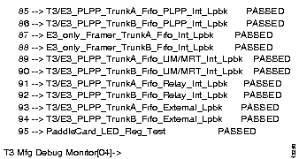
93 --> T3/E3_PLPP_TrunkA_Fifo_External_Lpbk
94 --> T3/E3_PLPP_TrunkB_Fifo_External_Lpbk
The medium-speed line card memory tests listed below take longer than one minute to run. Some take many minutes. (In field diagnostics, these tests are invoked when you use the test command's -x switch.)
14 --> CP_to_DRAM_AddrBus_Indep_Test
15 --> CP_to_DRAM_Marching_1s_Test
24 --> CP_to_TSU_CntrlRAM_AddrBus_Indep_Test
25 --> CP_to_TSU_CntrlRAM_Marching_1s_Test
54 --> CTP_Control_Ram_StuckBit_Test
56 --> CTP_Control_Ram_DataBus_WalkingBit_Tst
57 --> CTP_Control_Ram_RamData_Pattern_Test
61 --> CTP_Cell_Buffer_RamData_Pattern_Test
80 --> FSU_VRAM_Rrefresh_Test
The packet line card tests listed below send data through the switch card. (In field diagnostics, these tests are invoked when you use the test command's -s switch.) Take the LS2020 node off line before running these tests. Do not run them on a system that is passing traffic. (If the node is running, these tests may fail when they would otherwise pass. In addition, the "bad" data passed to the switch by the tests may cause traps.)
43          TSU_FSU_SWA_External_Lpbk_Test
46          TSU_FSU_SWB_External_Lpbk_Test
To run these tests, use the procedure below to disable the system and all the other cards in the chassis, and then to load the diagnostics into the card you wish to test. This procedure prevents the other cards from sending packets to the card under test that cause these tests to fail even when no problem exists.
Step 1 Log in as root or fldsup on the system you want to test.
Step 2 At the bash prompt, enter the command reboot -n to bring down the NP. If your system has two NPs, do the following to reboot the second one:
'. to get a TCS hub prompt.
Step 3 Enter '. to get a TCS hub prompt.
Step 4 From the TCS hub, enter reset <slot#> to reset each slot that has a line card in it. (Do not reset the switch card or NP slots.)
Step 5 Enter connect <slot#> to return to the NP, then press Return to display a menu of boot options.
Step 6 At the menu's Option prompt, enter 6, as shown below.
6
Step 7 The system displays the following message and a boot prompt. Enter the string shown below to load the system monitor, which you use to load the diagnostics.
(sd0b)diag/sys_np1.aout
Step 8 When the system monitor finishes loading, you see an identifying message and a prompt, as shown below. To load diagnostics, enter the command shown, replacing <slot#> with the number of the card you want to test.
swload <slot#> (sd0b)diag/diag_plc1.aout
Step 9 Wait about 5 minutes for the diagnostics to load. Then enter '. to return to the TCS hub.
Step 10 At the TCS hub prompt, use the command connect <slot#> to connect to the card you just loaded.
Step 11 Run the desired tests.
The PLC tests listed in this section fail if they are run on a system that does not have looping cables installed on the I/O ports. (In field diagnostics, these tests are invoked when you use the test command's -l switch.) The individual tests vary depending on whether your PLC is paired with a serial access card, an FDDI access card, an Ethernet access card, a fiber Ethernet access card, or a CEMAC. If you do not have looping cables installed, it is recommended that you avoid running these tests.
Serial
 55.04       Serial_V35_Ext_Loopback_Test
 55.05       Serial_RS449_Ext_Loopback_Test
 55.06       Serial_Clk_Ext_Lpbk_Test(1520)
 55.07       Serial_Clk_Ext_Lpbk_Intrlv_Test(64)
 55.12       Serial_Octart_Ext_Loopback_Test
 55.13       Serial_Clock_Measure_Test
 55.15       Serial_External_Loopback_Chain_Test
 55.16       Serial_X21_Self_Clocking_Ext_Lpbk_Test
CEMAC
 55.10       CEMAC_Nettime_PLL_SWA_Test
 55.11       CEMAC_Nettime_PLL_SWB_Test
 55.12       CEMAC_Nettime_PLL_SWA_SWB_Test
 55.13       CEMAC_Per_Port_External_Loopback_Test
 55.14       CEMAC_Multi_Ports_External_Loopback_Test
FDDI
 55.09       FDDI_LM_Loop_Test
 55.10       FDDI_EB_Loop_Test
 55.11       FDDI_FCG_Loop_Test
Ethernet
 55.12       Ethernet_Bus_External_Test
 55.14       Ethernet_XC_X_Loopback_Test
 55.15       Ethernet_XC_E_Loopback_Test
Fiber Ethernet
 55.12       Fiber_Ethernet_Bus_External_Test
 55.14       Fiber_Ethernet_XC_X_Loopback_Test
 55.15       Fiber_Ethernet_XC_E_Loopback_Test
The packet line card memory tests listed below take longer than one minute to run. Some take many minutes. (In field diagnostics, these tests are invoked when you use the test command's -x switch.)
03.01       CP_to_DRAM_AddrBus_Indep_Test
03.04       CP_to_DRAM_DataBus_WalkingBit_Test
03.07       CP_to_DRAM_Marching_1s_Test
03.08       CP_to_DRAM_Refresh_Test
07.01       CP_to_PDBL_SRAM_AddrBus_Indep_Test
07.04       CP_to_PDBL_SRAM_DataBus_WalkingBit_Test
07.07       CP_to_PDBL_SRAM_Marching_1s_Test
22.12       TSU_NQP_RamTests
22.13       TSU_DQP_RamTests
23.13       FSU_ISMC_RamTests
23.14       FSU_OSMC_RamTests
24.08       TLU_RP_RamTests
24.09       TLU_TLP_RamTests
25.06       FLU_ALF_RamTests
31.01       TSU_CBuf_DRAM_AddrBus_Indep_Test
31.04       TSU_CBuf_DRAM_DataBus_WalkingBit_Test
31.07       TSU_CBuf_DRAM_Marching_1s_Test
32.01       TSU_Ctrl_DRAM_AddrBus_Indep_Test
32.04       TSU_Ctrl_DRAM_DataBus_WalkingBit_Test
32.07       TSU_Ctrl_DRAM_Marching_1s_Test
34.01       FSU_LRIC_SRAM_AddrBus_Indep_Test
34.04       FSU_LRIC_SRAM_DataBus_WalkingBit_Test
34.07       FSU_LRIC_SRAM_Marching_1s_Test
35.01       FSU_CRIC_DRAM_AddrBus_Indep_Test
35.04       FSU_CRIC_DRAM_DataBus_WalkingBit_Test
35.07       FSU_CRIC_DRAM_Marching_1s_Test
36.01       TLU_Ext_DRAM_AddrBus_Indep_Test
36.04       TLU_Ext_DRAM_DataBus_WalkingBit_Test
36.07       TLU_Ext_DRAM_Marching_1s_Test
37.01       FLU_Parse_SRAM_AddrBus_Indep_Test
37.04       FLU_Parse_DRAM_DataBus_WalkingBit_Test
37.07       FLU_Parse_DRAM_Marching_1s_Test
38.01       FLU_Proto_DRAM_AddrBus_Indep_Test
38.04       FLU_Proto_DRAM_DataBus_WalkingBit_Test
38.07       FLU_Proto_DRAM_Marching_1s_Test
The cell line card tests listed below send data through the switch card. (In field diagnostics, these tests are invoked when you use the test command's -s switch.) Take the LS2020 node off line before running these tests. Do not run them on a system that is passing traffic. (If the node is running, these tests may fail when they would otherwise pass. In addition, the "bad" data passed to the switch by the tests may cause traps.)
36          Cell_lpbk_Tsu_A_Ext_SWA_Test
37          Cell_lpbk_Tsu_A_Ext_SWB_Test
38          Cell_lpbk_Tsu_B_Ext_SWA_Test
46          RATO_lpbk_Tsu_A_Ext_SWA_Test
47          Metering_lpbk_Tsu_A_Ext_SWA_Test
To run these tests, use the procedure below to disable the system and all the other cards in the chassis, and then to load the diagnostics into the card you wish to test. This procedure prevents the other cards from sending packets to the card under test that cause these tests to fail even when no problem exists.
Step 1 Log in as root or fldsup on the system you want to test.
Step 2 At the bash prompt, enter the command reboot -n to bring down the NP. If your system has two NPs, do the following to reboot the second one:
'. to get a TCS hub prompt.
Step 3 Enter '. to get a TCS hub prompt.
Step 4 From the TCS hub, enter reset <slot#> to reset each slot that has a line card in it. (Do not reset the switch card or NP slots.)
Step 5 Enter connect <slot#> to return to the NP, then press Return to display a menu of boot options.
Step 6 At the menu's Option prompt, enter 6, as shown below.
6
Step 7 The system displays the following message and a boot prompt. Enter the string shown below to load the system monitor, which you use to load the diagnostics.
(sd0b)diag/sys_np1.aout
Step 8 When the system monitor finishes loading, you see an identifying message and a prompt, as shown below. To load diagnostics, enter the command shown, replacing <slot#> with the number of the card you want to test.
swload <slot#> (sd0b)diag/diag_clc1.aout
Step 9 Wait about 5 minutes for the diagnostics to load. Then enter '. to return to the TCS hub.
Step 10 At the TCS hub prompt, use the command connect <slot#> to connect to the card you just loaded.
Step 11 Run the desired tests.
The CLC tests listed below fail if they are run on a system that does not have looping plugs installed on the I/O ports. (In field diagnostics, these tests are invoked when you use the test command's -l switch.) If you do not have looping plugs installed, it is recommended that you avoid running these tests:
OC-3c
49.03       OC3_Port_Extrnl_Loopback_Test
49.06       OC3_Port_0_1_X_Cross_Test
49.07       OC3_Port_0_1_X_Cross_Test_2
T3/E3
49.10 T3E3_PerPort_Extrnl_Lpbk_Test
The cell line card memory tests listed below take longer than one minute to run. Some take many minutes. (In field diagnostics, these tests are invoked when you use the test command's -x switch.)
03          CP_to_DRAM_AddrBus_Indep_Test
06          CP_to_DRAM_DataBus_WalkingBit_Test
09          CP_to_DRAM_Marching_1s_Test
10          CP_to_DRAM_Refresh_Test
26.13       FSU_ISMC_RamTests
26.14       FSU_OSMC_RamTests
27.12       TSU_NQP_RamTests
27.13       TSU_DQP_RamTests
28.12       TSU_B_NQP_RamTests
28.13       TSU_B_DQP_RamTests
29.01       TSU_CBuf_DRAM_AddrBus_Indep_Test
29.04       TSU_CBuf_DRAM_DataBus_WalkingBit_Test
29.07       TSU_CBuf_DRAM_Marching_1s_Test
30.01       TSU_Ctrl_DRAM_AddrBus_Indep_Test
30.04       TSU_Ctrl_DRAM_DataBus_WalkingBit_Test
30.07       TSU_Ctrl_DRAM_Marching_1s_Test
31.01       TSU_CBuf_DRAM_AddrBus_Indep_Test
31.04       TSU_CBuf_DRAM_DataBus_WalkingBit_Test
31.07       TSU_CBuf_DRAM_Marching_1s_Test
32.01       TSU_Ctrl_DRAM_AddrBus_Indep_Test
32.04       TSU_Ctrl_DRAM_DataBus_WalkingBit_Test
32.07       TSU_Ctrl_DRAM_Marching_1s_Test
34.01       FSU_LRIC_SRAM_AddrBus_Indep_Test
34.04       FSU_LRIC_SRAM_DataBus_WalkingBit_Test
34.07       FSU_LRIC_SRAM_Marching_1s_Test
35.01       FSU_CRIC_DRAM_AddrBus_Indep_Test
35.04       FSU_CRIC_DRAM_DataBus_WalkingBit_Test
35.07       FSU_CRIC_DRAM_Marching_1s_Test
This section alphabetically lists and describes selected commands that are available in LS2020 hardware diagnostic packages. Many commands are available in all three packages; others are specific to one or two packages. Each entry lists the packages in which the command is available.
! <command>
Causes the specified command to loop indefinitely. For example, the arun command runs all tests once; !arun cycles through all the tests repeatedly until you stop the loop, or, if stop on fail mode is on, until a test fails.
Availability: all packages
? [<command>]
Without argument: Displays a list of available commands.
With argument: Displays information on the specified command.
Availability: all packages
access [cemac | ethernet | fddi | fiberenet | serial]
access [oc3 | t3 | e3 | t1e1]
With no argument, displays the type of access card installed with the line card under test. With an argument, forces activation of the access card tests for the access card type indicated.
Availability: PLC and CLC diagnostics
arun
Runs all tests once. Not recommended if you do not have looping plugs or if you are running diagnostics remotely, as this command runs tests that require looping plugs.
Availability: all packages
bb_battery
Checks the status of the battery for the NP's battery-backed RAM. A screen display tells you that the battery is OK, or that it is low. The results of this command are valid only the first time the command is executed after powering up the NP. To get valid results again, you must power cycle the board.
Availability: NP diagnostics
blink [green | yellow | both] [1hz | 2hz | 4hz] [on | off]
In NP diagnostics: Causes the green RDY LED and/or the yellow FLT LED on the NP bulkhead to blink, turn on, or turn off.
blink [on | off]
In PLC and CLC diagnostics: Causes LNS OK LED on the bulkhead to blink (on) or not blink (off) during long-running tests. Blinking gives an indication that the tests are still running.
chprmpt <string>
Changes the diagnostics command prompt. Maximum prompt length is 30 characters.
Availability: all packages
cnt [<loop count>]
Specifies the count, or number of times the selected tests will be executed when you use the run command. Use cnt with no argument to display the current loop count.
Availability: all packages
dsel {all | <test#> | <test# range>}
Deselects all selected tests, a particular test, or a range of tests.
Availability: all packages
dsp_ver
Displays the firmware revision levels of the switch interface daughterboard's PCP, CMP, and FSU digital signal processors.
Availability: NP diagnostics
env
Displays the current test run environment as selected with the mod command.
Availability: all packages
execute [<test#> | <test# range>] [<-switches>] [argument] [argument] [argument] [argument]
Runs selected tests (with no argument), or specified tests. The switches, which temporarily override the mode settings, are as follows:
execute is the same as run and go.
Availability: all packages
You can also run tests using the execute or go commands, or by typing specific test numbers or ranges of numbers. (For example, enter 22 to run test 22.) You can use the switches for the run command with test numbers as well. Thus, for example, these two commands both cause tests 22 through 24 to loop indefinitely:
run 22-24 -l
22-24 -l
Availability: all packages
exit
Halts the diagnostics, resets the board, and transfers control to POST. (Same as quit.)
Availability: all packages
fl_format
Formats the diskette in the floppy drive.
Availability: NP diagnostics
fl_inq
Displays information on the floppy disk drive, including firmware revision level and model number.
Availability: NP diagnostics
go [<test#> | <test# range>] [<-switches>] [argument] [argument] [argument] [argument]
Runs the specified test or range of tests. go is the same as execute and run.
Availability: all packages
help [<command> | <test#>]
Provides three kinds of help:
Availability: all packages
history
Displays the last 50 commands entered. This command is useful in conjunction with ^P, which you can use to yank previous commands from the history buffer.
Availability: all packages
jumpers
Displays the following:
Availability: LSC diagnostics
led [<on | off>] [<channel>]
Turns the channel LEDs on the line card bulkhead on or off. Without an argument, led flashes the LEDs in succession until you press any key to stop the test. led on turns all the LEDs on; led off turns them all off. In conjunction with the on/off argument, the channel argument lets you turn particular LEDs on or off. On medium-speed cards, the channels are 0 and 1; on low-speed cards, the channels are 0 - 7. The following command turns LED 0 on:
led on 0
Availability: LSC and MSC diagnostics
loop [<loopcount>]
Sets the loop counter to the specified number. When you use execute, go or run, the selected tests repeat, or loop, the specified number of times.
Availability: all packages
l[i]st [all] [<test#> | <test# range>]
Lists selected tests (with no argument), all tests, a specific test, or a range of tests. (A range is expressed with a dash. For example, you might enter lst 1-6.)
In PLC and CLC diagnostics, tests are numbered hierarchically using both decimal and whole numbers. Similar tests are grouped together under the same number. For example, all the access card tests in PLC diagnostics are subtests of test number 55, and are numbered 55.01 to 55.15. If you enter lst or list in PLC or CLC diagnostics, only the top-level tests are listed. Enter lst all to list all the tests, including subtests.
Availability: all packages
macro
Lists all installed macros. Refer to the section "Macros ," later in this chapter, for information on installing and using macros.
Availability: all packages
mod <mode> = <0 | 1> | <on | off> | <number> | <off | hard |
soft | detailed | info>
Sets up the test environment, where mode is one of the following:
0 turns the specified mode off; 1 turns it on. For example, mod sof = 1 turns stop on fail mode on. 0 and 1 can be replaced with off and on. Thus, mod sof = on has the same effect as mod sof = 1.
Availability: all packages
quit
Halts the diagnostics, resets the board, and transfers control to POST. (Same as exit.)
Availability: NP diagnostics
rev
Displays information identifying the current revision of the diagnostics. rev is the same as ver.
Availability: all packages
run [<test#> | <test# range>] [<-switches>] [argument] [argument] [argument] [argument]
Runs selected tests (with no argument), or specified tests. The switches, which temporarily override the mode settings, are as follows:
run is the same as execute and go.
You can also run tests using the execute or go commands, or by typing specific test numbers or ranges of numbers. (For example, enter 22 to run test 22.) You can use the switches for the run command with test numbers as well. Thus, for example, these two commands both cause tests 22 through 24 to loop indefinitely:
run 22-24 -l
22-24 -l
Availability: all packages
scsi_reset
Resets the SCSI bus that communicates with the hard and floppy disk drives.
Availability: NP diagnostics
sel [<test#> | <test# range> | all]
Selects the test or tests to be run. The argument can be a single test number, a range of numbers (6 - 12, for example), or all (select all tests). Use run to execute selected tests. Use dsel to deselect tests.
Availability: all packages
status [all | clr | fail | <test#> | <test# range>]
Displays the status of selected tests (with no argument); all displays status for all tests; clr clears the status of selected tests; and fail displays the status of failed tests only. To display detailed status, use status and help together:
status<test#>;help<test#>
The help display explains the error codes used in the status display.
Availability: all packages
temp
Displays temperature readings for the card under test.
Availability: all packages
tod
Displays the current setting of the NP's time of day clock in Greenwich Mean Time.
Availability: NP diagnostics
ver
Displays information identifying the current version of the diagnostics. ver is the same as rev.
Availability: all packages
voltage
Displays voltage information for the card under test, as measured and reported by the TCS.
Availability: all packages
Any command can be abbreviated to the shortest string that uniquely identifies it in its diagnostic package. For example, you can enter ve to execute the ver (version) command.
Each diagnostics package lets you configure up to five macros, numbered 0 through 4. (Macros 0 and 1 are preconfigured to run sets of NP, LSC, and MSC diagnostic tests.) A macro can be a command or string of commands. Use the following syntax to install a macro:
_x=<command>
Where x is a macro number (0 - 4), and command is a command or a chain of commands.
In the following example, two macros are installed; the second incorporates the first.
_3=sel14-18; run
_4=_3; status
To execute a macro, enter its number preceded by an underscore: for example, _1. To list all the installed macros, use the macro command.
|
|