|
|

This chapter discusses the initial configuration of the LightStream 1010 Asynchronous Transfer mode (ATM) switch. Because the LightStream 1010 offers true plug-and-play operation, most users may not need to perform any of these procedures.
The LightStream 1010 is shipped with the ATM address autoconfigured to an address assigned by Cisco Systems. This feature lets the switch automatically configure attached end systems using the Interim Local Management Interface (ILMI) protocol and automatically establishes itself as a node in a single-level Private Network-Network Interface (PNNI) routing domain.
The ILMI and PNNI protocols, when used with such IP address autoconfiguration mechanisms as BOOTP, allow the LightStream 1010 to be entirely self-configured. Through network management applications and the text-based command line interface (CLI), the switch's network operator has the capability, if desired, to configure and customize all aspects of the operation of the switch.
An IP address must be assigned to allow up to eight simultaneous Telnet sessions to connect to the switch or to use Simple Network Management Protocol (SNMP) network management for the switch. The Ethernet IP address can be assigned either manually or by a BOOTP server. See the section "Configuring Ethernet IP Interface Parameters."
For definitions of all commands discussed in this chapter, refer to the publication LightStream 1010 ATM Switch Command Reference.
The following sections describe how to initially configure the LightStream 1010:
You may need the following information before you can begin your LightStream 1010 configuration if you want to configure some additional features:
To help configure your switch you should have already completed the worksheets in the section "Port Configuration Worksheets" in the appendix "Configuration Worksheets."
Before powering up your system, check for correct AC power voltages. See the appendix "System Specifications" for correct AC power voltages.
 | Warning This product relies on the building's installation for short-circuit (overcurrent) protection. Ensure that a fuse or circuit breaker no larger than 120 VAC, 15A U.S. (240 VAC, 10A international) is used on the phase conductors (all current-carrying conductors). To see translated versions of this warning, refer to the appendix "Translated Safety Warnings." |
| Warning Care must be given to connecting units to the supply circuit so that wiring is not overloaded. To see translated versions of this warning, refer to the appendix "Translated Safety Warnings." |
Now you can safely power up your system by flipping the power switch(es) on the power supply(ies).
When you first power up your console and LightStream 1010, a screen similar to the following appears:
              Restricted Rights Legend
Use, duplication, or disclosure by the Government is
subject to restrictions as set forth in subparagraph
(c) of the Commercial Computer Software - Restricted
Rights clause at FAR sec. 52.227-19 and subparagraph
(c) (1) (ii) of the Rights in Technical Data and Computer
Software clause at DFARS sec. 252.227-7013.
           cisco Systems, Inc.
           170 West Tasman Drive
           San Jose, California 95134-1706
Cisco Internetwork Operating System Software
IOS (tm) IISP Software (LS1010-WI-M), Version 11.1(1.083),
MAINTENANCE INTERIM SOFTWARE
Copyright (c) 1986-1996 by cisco Systems, Inc.
Compiled Wed 10-Apr-96 06:11 by
Image text-base: 0x600108C0, data-base: 0x602E8000
The first section of the script displays the banner information, including the software version.
The next portion of the script lists installed hardware configuration.
cisco ASP1 (R4600) processor with 16384K bytes of memory.
R4600 processor, Implementation 32, Revision 2.0
Last reset from power-on
1 Ethernet/IEEE 802.3 interface.
16 ATM network interfaces.
125K bytes of non-volatile configuration memory.
8192K bytes of Flash PCMCIA card at slot 0 (Sector size 128K).
8192K bytes of Flash internal SIMM (Sector size 256K).
Press RETURN to get started!
Switch>
Use the show hardware command to confirm installed hardware part and serial numbers:
Switch#show hardware
LS1010 named Switch, Date: 13:44:09 UTC Thu Apr 18 1996
Slot Ctrlr-Type   PartNo.    Rev Ser No  Mfg Date  RMA No. Hw Vrs Tst EEP
---- ----------   -------    --  ------  --------  ------ ------- ------
0/0  155UTP PAM   73-1572-02 01 02749041 1/17/96 00-00-00  3.0     0  2
0/1  155MM PAM    73-1496-03 06 02180424 1/16/96 00-00-00  3.0     0  2
1/0  155MM PAM    73-1496-03 06 02180444 1/17/96 00-00-00  3.0     0  2
1/1  155MM PAM    73-1496-03 06 02202228 1/11/96 00-00-00  3.0     0  2
2/0  ATM Swi/Proc 73-1402-02 00 02827677 0/07/13 00-00-00  2.3     0  2
The LightStream 1010 should be operating correctly and transferring data. To confirm that the hardware and software installation and configuration procedures were successful, see the chapter "Confirming the Installation."
The LightStream 1010 Ethernet IP address can be automatically assigned using the BOOTP protocol by adding the MAC and IP addresses of the Ethernet port to the BOOTP server configuration file. When the switch boots, it automatically retrieves the IP address from the BOOTP server.
The switch performs a BOOTP request only if the current IP address is set to 0.0.0.0. (This setting is the default for a new switch or a switch that has had its configuration file cleared using the erase startup-config command.)
To allow your LightStream 1010 to retrieve its IP address from a BOOTP server, find the MAC address label attached to the front of the switch. Add that MAC address to the BOOTP configuration file on the BOOTP server. The following tasks provide an example of creating a BOOTP server configuration file:
| Task | Command |
|---|---|
| Install the BOOTP server code on the workstation if it is not already installed. | None |
| The switch MAC address is printed on a label attached to the front of the switch. | None |
| Add an entry in the BOOTP configuration file (usually /usr/etc/bootptab) for each switch. Press Return after each entry to create a blank line between each entry. Figure 6-1 is an example of a server BOOTP configuration file. | None |
| Restart the LightStream 1010 to automatically request the IP address from the BOOTP server. | Restart |
# /etc/bootptab: database for bootp server (/etc/bootpd)
#
# Blank lines and lines beginning with '#' are ignored.
#
# Legend:
#
#       first field -- hostname
#                       (may be full domain name and probably should be)
#
#       hd -- home directory
#       bf -- bootfile
#       cs -- cookie servers
#       ds -- domain name servers
#       gw -- gateways
#       ha -- hardware address
#       ht -- hardware type
#       im -- impress servers
#       ip -- host IP address
#       lg -- log servers
#       lp -- LPR servers
#       ns -- IEN-116 name servers
#       rl -- resource location protocol servers
#       sm -- subnet mask
#       tc -- template host (points to similar host entry)
#       to -- time offset (seconds)
#       ts -- time servers
#
# Be careful about including backslashes where they're needed. Weird (bad)
# things can happen when a backslash is omitted where one is intended.
#
# First, we define a global entry which specifies the stuff every host uses.
<information deleted>
#########################################################################
# Start of individual host entries
#########################################################################
switch:         tc=netcisco0:   ha=0000.0ca7.ce00:      ip=192.31.7.97:
dross:          tc=netcisco0:   ha=00000c000139:        ip=192.31.7.26:
<information deleted>
The LightStream 1010 ATM switch is autoconfigured with an ATM address using a hierarchical addressing model similar to the Open System Interconnection (OSI) network service access point (NSAP) addresses. PNNI uses this hierarchy to construct ATM peer groups.
During the initial startup, the LightStream 1010 generates an ATM address using the defaults shown in Figure 6-2.
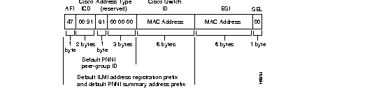
The switch's ATM address uses a hierarchical addressing model similar to the Open System Interconnect (OSI) network service access point (NSAP) addresses. PNNI uses this hierarchy to construct ATM peer groups. ILMI uses the first 13-bytes of this address as the switch prefix that it registers with end systems.
Using the default address format has the following features and implications:
To configure a new ATM address that replaces the previous ATM address when running IISP software only, see the section "Configure the ATM Address" in the chapter "Configuring ILMI" in the LightStream 1010 ATM Switch Software Configuration Guide.
To configure a new ATM address that replaces the previous ATM address and generates a new PNNI node ID and peer group ID, see the section "Configure PNNI Node" in the chapter "Configuring PNNI" in the LightStream 1010 ATM Switch Software Configuration Guide.
Multiple addresses can be configured for a single switch and this configuration can be used during ATM address migration. ILMI registers end systems with multiple prefixes during this period until an old address is removed. PNNI automatically summarizes all of the switch prefixes in its reachable address advertisement.
If operation with ATM addresses other than the autoconfigured ATM address is desired, use the atm address command to manually assign a 20-byte ATM address to the switch. The atm address command address_template variable can be a full 20-byte address or a 13-byte prefix followed by ellipsis (...). Entering the ellipsis will automatically add one of the switch's 6-byte MAC addresses in the ESI portion and 0 in the selector portion of the address.
 | Caution ATM addressing may lead to conflicts if not configured correctly. The correct address must always be present. For instance, if you are configuring a new ATM address, the old one must be completely removed from the configuration. |
To set the ATM address manually, refer to the LightStream 1010 ATM Switch Software Configuration Guide.
When the switch is powered on initially without any previous configuration data, the ATM interfaces are automatically configured on the physical ports. ILMI and the physical card type are used to automatically derive the ATM interface type, UNI version, maximum virtual path identifier (VPI) and virtual channel identifier (VCI) bits, ATM interface side, and ATM UNI type.
If ILMI has been disabled or if the connecting end node does not support ILMI, the following defaults are assigned to all interfaces:
The following PAM types have specific defaults assigned:
OC3 PAM:
OC12 PAM:
DS3 PAM:
E3 PAM:
You can accept the default ATM interface configuration or overwrite the default interface configuration using the CLI commands. These commands are described in the LightStream 1010 ATM Switch Software Configuration Guide, which provides detailed ATM interface configuration tasks.
Three different IP addresses may be configured on the LightStream 1010. The IP address for the Ethernet port, classical IP over ATM, and a LAN emulation (LANE) client. Each IP address is configured using one of the following methods:
Configure the interface to communicate with the switch central processor unit (CPU) (interface 2/0/0) or Ethernet interface 2/0/0 using the following information as a guide:
Provide the IP address and subnet mask bits for the interface as follows:
| First Class | First Byte | Network Bits | Host Bits | |
|---|---|---|---|---|
| Max Subnet Bits | Min Address Bits | |||
| A | 1-126 | 8 | 22 | 2 |
| B | 128-191 | 16 | 14 | 2 |
| C | 192-223 | 24 | 6 | 2 |
Define subnet mask bits as a decimal number between 0 and 22 for Class A addresses, 0 and 14 for Class B addresses, or 0 and 6 for Class C addresses. Do not specify 1 as the number of bits for the subnet field. That specification is reserved by Internet conventions.
The default software image for the LightStream 1010 will contain only the IISP routing protocol. This will be suitable for small networks that do not require the sophistication of the PNNI protocols. A separate orderable image contains both PNNI and IISP protocols. The PNNI protocol provides the route dissemination mechanism for complete plug-and-play capability.
The following section describes modifications that may be made to the default PNNI or IISP routing configurations:
For detailed descriptions of these routing protocols see the section "ATM Routing" in the chapter "What is the LightStream 1010 ATM Switch?"
The PNNI routing protocol automatically creates peer groups that are a collection of logical nodes, each of which exchanges information with the other members of the group, so that all members maintain an identical view of the group. For example, hellos, database synchronization, and flooding are carried out among members of the same peer group. All members of the same peer group have the same 13-byte PNNI prefix in their ATM address. A peer group can be considered similar to either open shortest path first (OSPF) or IP routing domains, depending on usage.
This peer group configuration information is in the hierarchy database stored within each switch and updated regularly.
The following section will discuss manually configuring two autonomous peer groups to create one single peer group.
To manually configure two autonomous peer groups into one, all members of the peer group must have the same peer group ID in their ATM address. The following sections describe the manual PNNI peer-group modification process:
Use the show pnni node-id command to determine the peer-group IDs to modify:
| Task | Command |
|---|---|
| Display ATM address prefix | show atm pnni node-id |
Switch#show atm pnni node-id
  Node    Node Id
  ----    -------
  1       56:160:47.000000000000000000000000.000000005656.00
Switch#
The atm address command assigns a 20-byte ATM address to the switch. See the section "ATM Address Configuration" for a complete description of this command.
Multiple addresses can be configured for a single switch and this can be used during address migration. ILMI would register end systems with multiple prefixes during this period until an old address is removed. PNNI automatically summarizes all switch prefixes in its reachable address advertisement.
To configure the ATM address manually, use the following commands using the no form of this command to disable.
| Task | Command |
|---|---|
| At the privileged EXEC prompt, enter configuration mode from the terminal | configure1 [terminal] |
| Change 13 byte ATM prefix in the ATM address to match the desired switch prefix | atm address 13_byte_switch _prefix ... |
| Delete the old ATM address | no atm address 13_byte_switch_prefix ... |
| Start PNNI configuration mode | atm router pnni |
| Disable the node | atm node 1 disable |
| Enable the node | atm node 1 enable |
| Restart PNNI to force it to read the new node IDs. | restart pnni |
The following steps configure a peer-group ID manually:
Step 1 Adds the ATM address prefix 47.0091.8100.5670.000.0ca7.ce01, (...), and adds the default MAC address as the last six bytes.
Step 2 Deletes the old ATM address prefix.
Step 3 Starts PNNI configuration mode.
Step 4 Disables ATM node 1.
Step 5 Reenables node 1.
Step 6 Restarts PNNI.
Switch(config)#atm address 47.0091.8100.5670.0000.0ca7.ce01...
Switch(config)#no atm address 47.0091.8100.1200.0000.0ca7.ce01...
Switch(config)#atm router pnni
Switch(config)#atm node 1 disable
Switch(config)#atm node 1 enable
Switch(config)#restart pnni
Use the atm route command to configure a static route. A static route attached to an interface allows all ATM address prefixes where the static route is a match to be reached through that interface.
Figure 6-3 is an example of the atm route command configuring a static route to the 13-byte-switch-prefix = 47.0091.8100.567.0000.0ca7.ce01 to interface 3/0/0.
Switch(config)#atm route 47.0091.8100.567.0000.0ca7.ce01 atm 3/0/0
Switch(config)#
Although not required, several system parameters should be set as part of the initial system configuration. These system information commands make troubleshooting and configuring the switches easier. To set the system parameters, perform the following tasks in EXEC mode:
| Task | Command |
|---|---|
| Set the system clock. | clock set hh:mm:ss |
| At the privileged EXEC prompt, enter configuration mode from the terminal. | configure1 [terminal] |
| Set the system name. | hostname name_string |
SNMP, an application-layer protocol, facilitates the exchange of Management Information Bases (MIBs) between network devices. SNMP community strings authenticate access to the MIB and function as embedded "passwords."
To manually configure the LightStream 1010 SNMP, refer to the LightStream 1010 ATM Switch Software Configuration Guide. For definitions of all commands discussed in this chapter, refer to the publication LightStream 1010 ATM Switch Command Reference.
When autoconfiguration and any manual configurations are complete, you should copy the configuration into nonvolatile random-access memory (NVRAM). If you should power off your LightStream 1010 prior to saving the configuration in NVRAM, all manual configuration changes will be lost. Figure 6-4 is an example of the copy running-config startup-config command.
Switch#copy running-config startup-config
Warning: Attempting to overwrite an NVRAM configuration previously written
by a different version of the system image.
Overwrite the previous NVRAM configuration?[confirm]
Building configuration...
[OK]Switch#
The following sections describe commands that may be used to confirm that the hardware, software, and interfaces for the LightStream 1010 are configured as intended:
Use the show version command to confirm that the correct version and type of LightStream 1010 software is installed. Figure 6-5 is an example of the show version command.
Switch#show version
Cisco Internetwork Operating System Software
IOS (tm) IISP Software (LS1010-WI-M), Version 11.1(1.083),
MAINTENANCE INTERIM SOFTWARE
Copyright (c) 1986-1996 by cisco Systems, Inc.
Compiled Wed 10-Apr-96 06:11 by
Image text-base: 0x600108C0, data-base: 0x602E8000
ROM: System Bootstrap, Version 11.0(5726), INTERIM SOFTWARE
Switch uptime is 4 days, 1 hour, 13 minutes
System restarted by power-on
System image file is "slot0:rhino/ls1010-wi-m_1.083.bin.Z", booted via console
cisco ASP1 (R4600) processor with 16384K bytes of memory.
R4600 processor, Implementation 32, Revision 2.0
Last reset from power-on
1 Ethernet/IEEE 802.3 interface.
16 ATM network interfaces.
125K bytes of non-volatile configuration memory.
8192K bytes of Flash PCMCIA card at slot 0 (Sector size 128K).
8192K bytes of Flash internal SIMM (Sector size 256K).
Configuration register is 0x0
Switch#
Use the show hardware command to confirm the type of hardware installed in the system. Figure 6-7 is an example of the show hardware command.
Switch#show hardware
LS1010 named Switch, Date: 07:09:00 UTC Wed Apr 24 1996
Slot Ctrlr-Type    Part No.  Rev  Ser No  Mfg Date  RMA No. Hw Vrs  Tst EEP
---- ------------  ---------- -- -------- -------- -------- ------- --- ---
0/0  155UTP PAM    73-1572-02 01 02749041  1/17/96 00-00-00   3.0     0   2
0/1  155MM PAM     73-1496-03 06 02180424  1/16/96 00-00-00   3.0     0   2
1/0  155MM PAM     73-1496-03 06 02180444  1/17/96 00-00-00   3.0     0   2
1/1  155MM PAM     73-1496-03 06 02202228  1/11/96 00-00-00   3.0     0   2
2/0  ATM Swi/Proc  73-1402-02 00 02827677  0/07/13 00-00-00   2.3     0   2
Switch#
Use the show interface ethernet command to confirm that the Ethernet interface on the ASP is configured correctly. Figure 6-7 is an example of the show interface ethernet command.
Switch#show interface ethernet 2/0/0
Ethernet2/0/0 is up, line protocol is up
  Hardware is SonicT, address is 0000.0b0a.1000 (bia 0040.0b0a.1080)
  Internet address is 80.0.0.10/8
  MTU 1500 bytes, BW 10000 Kbit, DLY 1000 usec, rely 255/255, load 1/255
  Encapsulation ARPA, loopback not set, keepalive set (10 sec)
  ARP type: ARPA, ARP Timeout 04:00:00
  Last input never, output 00:00:05, output hang never
  Last clearing of "show interface" counters never
  Output queue 0/40, 0 drops; input queue 0/75, 0 drops
  5 minute input rate 0 bits/sec, 0 packets/sec
  5 minute output rate 0 bits/sec, 0 packets/sec
     0 packets input, 0 bytes, 0 no buffer
     Received 0 broadcasts, 0 runts, 0 giants
     0 input errors, 0 CRC, 0 frame, 0 overrun, 0 ignored, 0 abort
     0 input packets with dribble condition detected
     40894 packets output, 3907161 bytes, 0 underruns
     0 output errors, 0 collisions, 1 interface resets
     0 babbles, 0 late collision, 0 deferred
     0 lost carrier, 0 no carrier
     0 output buffer failures, 0 output buffers swapped out
Switch#
Use the show atm address command to confirm the ATM address for the LightStream 1010 is configured correctly. Figure 6-8 is an example of the show atm address command.
Switch#show atm address
Switch Address(es):
  47.00918100000000410B0A1081.00410B0A1081.00 active
  47.00918100000000603E5ADB01.00603E5ADB01.00
Soft VC Address(es):
  47.0091.8100.0000.0041.0b0a.1081.4000.0c80.0000.00 ATM0/0/0
  47.0091.8100.0000.0041.0b0a.1081.4000.0c80.0000.63 ATM0/0/0.99
  47.0091.8100.0000.0041.0b0a.1081.4000.0c80.0010.00 ATM0/0/1
  47.0091.8100.0000.0041.0b0a.1081.4000.0c80.0020.00 ATM0/0/2
  47.0091.8100.0000.0041.0b0a.1081.4000.0c80.0030.00 ATM0/0/3
  47.0091.8100.0000.0041.0b0a.1081.4000.0c80.1000.00 ATM0/1/0
  47.0091.8100.0000.0041.0b0a.1081.4000.0c80.1010.00 ATM0/1/1
  47.0091.8100.0000.0041.0b0a.1081.4000.0c80.1020.00 ATM0/1/2
  47.0091.8100.0000.0041.0b0a.1081.4000.0c80.1030.00 ATM0/1/3
  47.0091.8100.0000.0041.0b0a.1081.4000.0c80.8000.00 ATM1/0/0
  47.0091.8100.0000.0041.0b0a.1081.4000.0c80.8010.00 ATM1/0/1
  47.0091.8100.0000.0041.0b0a.1081.4000.0c80.8020.00 ATM1/0/2
  47.0091.8100.0000.0041.0b0a.1081.4000.0c80.8030.00 ATM1/0/3
  47.0091.8100.0000.0041.0b0a.1081.4000.0c80.9000.00 ATM1/1/0
  47.0091.8100.0000.0041.0b0a.1081.4000.0c80.9010.00 ATM1/1/1
  47.0091.8100.0000.0041.0b0a.1081.4000.0c80.9020.00 ATM1/1/2
  47.0091.8100.0000.0041.0b0a.1081.4000.0c80.9030.00 ATM1/1/3
ILMI Switch Prefix(es):
  47.0091.8100.0000.0041.0b0a.1081
  47.0091.8100.0000.0060.3e5a.db01
ILMI Configured Interface Prefix(es):
LECS Address(es):
Switch#
After you have configured the IP address(es) for the Ethernet interface, test for connectivity between the switch and a host. The host can reside anywhere in your network. To test for Ethernet connectivity, perform the following tasks:
| Task | Command |
|---|---|
| Test the configuration using the ping command. The ping command sends an echo request to the host specified in the command line. | ping [protocol] {host | address} |
For example, to test Ethernet connectivity from the switch to a workstation with an IP address of 192.34.56.5, enter the command ping 192.34.56.5. If the switch receives a response, a message is displayed as show, in Figure 6-9.
Switch#ping ip 172.20.40.201
Type escape sequence to abort.
Sending 5, 100-byte ICMP Echos to 172.20.40.201, timeout is 2 seconds:
!!!!!
Success rate is 100 percent (5/5), round-trip min/avg/max = 1/202/1000 ms
Switch#
Use the ping atm command to confirm that the ATM interfaces are configured correctly. Figure 6-10 is an example of the ping atm command.
Switch#ping atm interface atm 3/0/0 0 5 seg-loopback
Type escape sequence to abort.
Sending Seg-Loopback 5, 53-byte OAM Echoes to a neighbour,timeout is 5 seconds:
.....
Success rate is 0 percent (0/5)
Switch#
Use the show atm interface command to confirm that the atm interfaces are configured correctly. Figure 6-11 is an example of the show atm interface command.
Switch#show atm interface
Interface:      ATM0/0/0        Port-type:    oc3suni
IF Status:      UP              Admin Status: up
Auto-config:    disabled        AutoCfgState: not applicable
IF-Side:        User            IF-type:      IISP
Uni-type:       not applicable  Uni-version:  V3.0
Max-VPI-bits:   8               Max-VCI-bits: 14
Max-VP:         255             Max-VC:       32768
ATM Address for Soft VC: 47.0091.8100.0000.0060.3e5a.db01.4000.0c80.0000.00
Configured virtual links:
  PVCLs SoftVCLs   SVCLs   PVPLs SoftVPLs   SVPLs  Total-Cfgd  Installed-Conns
      4        0       0       1        0       0           5                4
Logical ports(VP-tunnels):     1
Input cells:    23355           Output cells: 27251
5 minute input rate:             0 bits/sec,       0 cells/sec
5 minute output rate:            0 bits/sec,       0 cells/sec
Input AAL5 pkts: 23355, Output AAL5 pkts: 27247, AAL5 crc errors: 0
Logical ports(VP-tunnels):     0
Input cells:    0               Output cells: 0
5 minute input rate:             0 bits/sec,       0 cells/sec
5 minute output rate:            0 bits/sec,       0 cells/sec
Input AAL5 pkts: 0, Output AAL5 pkts: 0, AAL5 crc errors: 0
<information deleted>
Interface:      ATM2/0/0        Port-type:    cpu
IF Status:      UP              Admin Status: up
Auto-config:    disabled        AutoCfgState: not applicable
IF-Side:        not applicable  IF-type:      not applicable
Uni-type:       not applicable  Uni-version:  not applicable
Max-VPI-bits:   8               Max-VCI-bits: 14
Max-VP:         0               Max-VC:       32768
Configured virtual links:
  PVCLs SoftVCLs   SVCLs   PVPLs SoftVPLs   SVPLs  Total-Cfgd  Installed-Conns
     53        0       0       0        0       0          53               18
Logical ports(VP-tunnels):     0
Input cells:    21973           Output cells: 21980
5 minute input rate:             0 bits/sec,       0 cells/sec
5 minute output rate:            0 bits/sec,       0 cells/sec
Input AAL5 pkts: 21875, Output AAL5 pkts: 21878, AAL5 crc errors: 0
Switch#
Use the show atm status command to confirm the status of the ATM interfaces. Figure 6-12 is an example of the show atm status command.
Switch#show atm status
NUMBER OF INSTALLED CONNECTIONS: (P2P=Point to Point, P2MP=Point to MultiPoint)
Type       PVCs  SoftPVCs      SVCs      PVPs  SoftPVPs      SVPs      Total
P2P          30         0         0         0         0         0         30
P2MP          0         0         0         0         0         0          0
                                    TOTAL INSTALLED CONNECTIONS =         30
PER-INTERFACE STATUS SUMMARY AT 13:50:30 UTC Tue Apr 16 1996:
   Interface      IF         Admin  Auto-Cfg    ILMI Addr     SSCOP
     Name       Status      Status    Status    Reg State     State
------------- -------- ------------ -------- ------------ ---------
ATM0/0/0            UP           up      n/a          n/a    Active
ATM0/0/0.99         UP           up      n/a          n/a  OConPend
ATM0/0/1            UP           up      n/a          n/a    Active
ATM0/0/2            UP           up      n/a          n/a    Active
ATM0/0/3            UP           up     done  UpAndNormal    Active
ATM0/1/0            UP           up     done  UpAndNormal    Active
ATM0/1/1            UP           up     done  UpAndNormal    Active
ATM0/1/2          DOWN         down  waiting          n/a      Idle
Switch#
Use the show atm vc command to confirm the status of ATM virtual interfaces. Figure 6-13 is an example of the show atm vc command.
Switch#show atm vc
Interface    VPI     VCI     Type   X-Interface  X-VPI   X-VCI   Status
ATM0/0/0     0       5        PVC     ATM2/0/0     0       32      UP
ATM0/0/0     0       16       PVC     ATM2/0/0     0       33      UP
ATM0/0/0     0       18       PVC     ATM2/0/0     0       34      UP
ATM0/0/0     0       89       PVC     ATM0/0/0.99  99      100     UP
ATM0/0/0.99  99      3        PVC     ATM2/0/0     0       83      UP
ATM0/0/0.99  99      4        PVC     ATM2/0/0     0       84      UP
ATM0/0/0.99  99      5        PVC     ATM2/0/0     0       80      UP
ATM0/0/0.99  99      16       PVC     ATM2/0/0     0       81      UP
ATM0/0/0.99  99      18       PVC     ATM2/0/0     0       82      UP
ATM0/0/0.99  99      100      PVC     ATM0/0/0     0       89      UP
ATM0/0/1     0       5        PVC     ATM2/0/0     0       35      UP
ATM0/0/1     0       16       PVC     ATM2/0/0     0       36      UP
ATM0/0/1     0       18       PVC     ATM2/0/0     0       37      UP
ATM0/0/2     0       5        PVC     ATM2/0/0     0       38      UP
ATM0/0/2     0       16       PVC     ATM2/0/0     0       39      UP
ATM0/0/2     0       18       PVC     ATM2/0/0     0       40      UP
ATM0/0/3     0       5        PVC     ATM2/0/0     0       41      UP
ATM0/0/3     0       16       PVC     ATM2/0/0     0       42      UP
<Information Deleted>
ATM2/0/0     0       66       PVC     ATM1/0/3     0       16      UP
ATM2/0/0     0       67       PVC     ATM1/0/3     0       18      UP
ATM2/0/0     0       68       PVC     ATM1/1/0     0       5       DOWN
ATM2/0/0     0       69       PVC     ATM1/1/0     0       16      DOWN
ATM2/0/0     0       70       PVC     ATM1/1/0     0       18      DOWN
ATM2/0/0     0       71       PVC     ATM1/1/1     0       5       DOWN
ATM2/0/0     0       72       PVC     ATM1/1/1     0       16      DOWN
ATM2/0/0     0       73       PVC     ATM1/1/1     0       18      DOWN
ATM2/0/0     0       74       PVC     ATM1/1/2     0       5       DOWN
Switch#
Use the show running-config command to confirm that the configuration being used is configured correctly. Figure 6-14 is an example of the show running-config command.
Switch#show running-config
Switch#write terminal
Building configuration...
Current configuration:
!
version 11.1
no service pad
service udp-small-servers
service tcp-small-servers
!
hostname Switch
!
boot system flash slot0:rhino/ls1010-wi-m_1.083.bin.Z
!
atm over-subscription-factor 16
atm service-category-limit cbr 3000
atm qos uni3-default  cbr max-cell-loss-ratio 12
atm address 47.0091.8100.0000.0060.3e5a.db01.0060.3e5a.db01.00
!
interface ATM0/0/0
 no keepalive
 no atm auto-configuration
 no atm ilmi-enable
 no atm ilmi-lecs-implied
 atm iisp side user
 atm pvp 99
<information deleted>
end
Switch#
Use the show startup-config command to confirm that the configuration saved in NVRAM is configured correctly. Figure 6-15 is an example of the show startup-config command.
Switch#show startup-config
Using 1830 out of 129016 bytes
!
version 11.1
no service pad
service udp-small-servers
service tcp-small-servers
!
hostname Switch
!
boot system flash slot0:rhino/ls1010-wi-m_1.083.bin.Z
!
atm over-subscription-factor 16
atm service-category-limit cbr 3000
atm qos uni3-default  cbr max-cell-loss-ratio 12
atm address 47.0091.8100.0000.0060.3e5a.db01.0060.3e5a.db01.00
<information deleted>
!
interface ATM0/0/0.99 point-to-point
 no atm ilmi-enable
 no atm ilmi-lecs-implied
 atm maxvp-number 0interface ATM0/0/2
 no keepalive
 no atm ilmi-enable
 no atm ilmi-lecs-implied
 atm iisp side user
!
end
Switch#
|
|