|
|

This chapter provides physical and functional overviews of the PA-H Rev. B HSSI port adapter. The chapter contains the following sections:
The HSSI port adapter (PA-H Rev. B) provides one high-speed serial interface. (See Figure 1-1.)

The HSSI port is a female, 50-pin, SCSI-II-type connector. You must use an HSSI interface cable to connect the interface with an external data service unit (DSU). Refer to the section "HSSI Port Adapter Receptacles, Cables, and Pinouts," for descriptions of HSSI cables.
The HSSI port adapter conforms to BABT/TC/130 and EIA/TIA-612 and EIA/TIA-613 standards. PA-H provides a single network interface for Cisco 7000 series or Cisco 7500 series routers. Each HSSI provides a full-duplex synchronous serial interface for transmitting and receiving data at rates of up to 52 megabits per second (Mbps).
HSSI, which was recently standardized as EIA/TIA 612/613, provides access to services at T3 (45 Mbps), E3 (34 Mbps), and Synchronous Optical Network (SONET) STS-1 (51.82 Mbps) rates. The actual rate of the interface depends on the external data service unit (DSU) and the type of service to which it is connected.
The port adapter supports both 16- and 32-bit cyclic redundancy checks (CRCs). The default is 16-bit CRCs; to enable 32-bit CRCs, you use a configuration command. (For a description of the CRC function, refer to the section "Configuring Cyclic Redundancy Checks" in the chapter "Cable Installation and Interface Configuration," later in this document.)
The BABT605559 marking on the HSSI port adapter signifies that the port adapter meets United Kingdom directive 605559 and has been designed to BABT/TC/130 standards. The BABT label is located on the top of each HSSI port adapter (PA-H).
Figure 1-2 shows the BABT label for the HSSI port adapter.

This newest single-port HSSI port adapter can be identified by Rev. B in the lower right corner of its front-panel label (see Figure 1-1), while the older HSSI port adapter does not have Rev. B on its label (see Figure 1-3). (We recommend that you use the HSSI Rev. B port adapter shown in Figure 1-1.)

The HSSI port adapter can be installed in the following slots on the hardware platforms described in this document:
Port adapters have a handle attached, but this handle is occasionally not shown to allow a full view of detail on the port adapter's faceplate.
Figure 1-4 shows a VIP2-15 or VIP2-40 with installed port adapters. With the VIP2 oriented as shown in Figure 1-4, the left port adapter is in port adapter slot 0, and the right port adapter is in port adapter slot 1.

Figure 1-5 shows a VIP2-50 with installed port adapters.

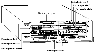
Figure 1-6 shows a Cisco 7206 with port adapters installed. In the Cisco 7206, port adapter slot 1 is in the lower left position, and port adapter slot 6 is in the upper right position. (The Cisco 7204 is not shown, but has four port adapter slots; PA-H can be installed in any of these four port adapter slots.)

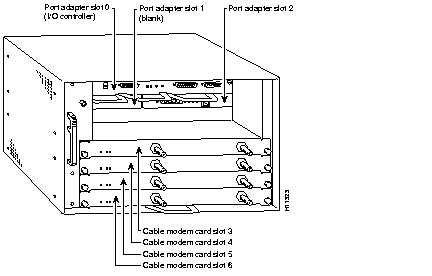
Figure 1-7 shows a Cisco uBR7246 with port adapters installed. In the Cisco uBR7246, port adapter slot 1 is in the upper left position, and port adapter slot 2 is in the upper right position. The port adapters are recessed into the chassis just below the I/O controller.

The HSSI port adapter has two rows of five status LEDs, one row of five for each HSSI port on the port adapter (TD, TC, RD, RC, and LB/C), and one enabled LED for the port adapter. (See Figure 1-8.)

After system initialization, the enabled LED, which is present on all interface processors, goes on to indicate that the port adapter has been enabled for operation.
The following conditions must be met before the HSSI port adapter is enabled:
If any of these conditions is not met, or if the initialization fails for other reasons, the enabled LED does not go on.
The five additional status LEDs on the HSSI port adapter indicate the following:
Two types of cables are available for use with the HSSI port adapter: the HSSI interface cable used to connect your router to an external DSU (and HSSI network) and a null modem cable, which allows you to connect two routers back to back. Both HSSI cables conform to EIA/TIA-612 and EIA/TIA-613 specifications. The HSSI port on PA-H is considered to be a DTE device.
The HSSI cable (CAB-HSI1=) connects the HSSI port adapter with the external DSU. The HSSI cable is 10-feet (3.048 meters) long. The maximum cable length is 50 feet (15.24 meters). Figure 1-9 shows the HSSI cable. Table 1-1 lists the pinout.

| Signal Name | + Side Pin No. | - Side Pin No. | Direction1 Router DSU |
|---|---|---|---|
| SG (Signal Ground) | 1 | 26 | -- |
| RT (Receive Timing) | 2 | 27 | <-- |
| CA (DCE Available) | 3 | 28 | <-- |
| RD (Receive Data reserved) | 4 | 29 | <-- |
| LC (Loopback circuit C) | 5 | 30 | <-- |
| ST (Send Timing) | 6 | 31 | <-- |
| SG (Signal Ground) | 7 | 32 | -- |
| TA (DTE Available) | 8 | 33 | --> |
| TT (Terminal Timing) | 9 | 34 | --> |
| LA (Loopback circuit A) | 10 | 35 | --> |
| SD (Send Data) | 11 | 36 | --> |
| LB (Loopback circuit B) | 12 | 37 | --> |
| SG (Signal Ground) | 13 | 38 | -- |
| 5 (Ancillary to DCE) | 14-18 | 39-43 | --> |
| SG (Signal Ground) | 19 | 44 | -- |
| 5 (Ancillary from DCE) | 20-24 | 45-49 | <-- |
| SG (Signal Ground) | 25 | 50 | -- |
The null modem cable (CAB-HNUL=) can connect two routers directly back to back. The null modem cable is 10-feet (3.048 meters) long. The maximum null modem cable length allowed is 50 feet (15.24 meters). The two routers must be in the same location and can be two Cisco 7000 series routers, two Cisco 7500 series routers, two Cisco 7200 series routers, two Cisco uBR7246 universal broadband routers, or any combination of each. A null modem connection allows you to verify the operation of the HSSI or to link the routers directly in order to build a larger node. Figure 1-10 shows the null modem cable. The null modem cable uses the same 50-pin connectors as the HSSI cable, but uses the pinout listed in Table 1-2. (For connection and configuration instructions, refer to the section "Attaching a Null Modem Cable" in the chapter "Cable Installation and Interface Configuration," later in this document.)

| Signal Name | From Pins | Direction | To Pins | Signal Name |
|---|---|---|---|---|
| RT (Receive Timing) | 2, 27 | --> | 9, 34 | TT (Terminal Timing) |
| CA (DCE available) | 3, 28 | --> | 8, 33 | TA (DTE Available) |
| RD (Receive Data) | 4, 29 | --> | 11, 36 | SD (Send Data) |
| LC (Loopback C) | 5, 30 | --> | 10, 35 | LA (Loopback A) |
| ST (Send Timing) | 6, 31 | --> | 6, 31 | ST (Send Timing) |
| TA (DTE available) | 8, 33 | --> | 3, 28 | CA (DCE Available) |
| TT (Terminal Timing) | 9, 34 | --> | 2, 27 | RT (Receive Timing) |
| LA (Loopback A) | 10, 35 | --> | 5, 30 | LC (Loopback C) |
| SD (Send Data) | 11, 36 | --> | 4, 29 | RD (Receive Data) |
| GND (Ground) | 1, 26, 7, 32, 13, 38, 19, 44, 25, 50 | 1, 26, 7, 32, 13, 38, 19, 44, 25, 50 | GND (Ground) | |
| Loopback (not connected) | 12, 37 | |||
| 12, 37 | Loopback (not connected) | |||
| Not used | 14-18, 20-24, 39-43, 45-49 | 14-18, 20-24, 39-43, 45-49 | Not used |
 | Caution Although the HSSI connector and the HSSI cable are similar to SCSI-II format, they are not identical. The HSSI cable specification is more stringent than that for the SCSI-II. If a SCSI-II cable is used instead of an HSSI cable, proper operation cannot be guaranteed. |
|
|