|
|

Product Numbers: MAS-7200FAN=, MAS-7206MP=, MAS-7204MP=, CISCO7204=, CISCO7206=
This document explains how to remove and replace the subchassis and the fan tray in the Cisco 7200 series routers. It includes instructions for powering down the router, removing the subchassis, removing the fan tray from the subchassis, installing a new fan tray in a new subchassis, and installing the new subchassis in the router. This document also includes steps for verifying a successful router boot after powering up the router.
The fan tray is housed in the subchassis; therefore, you must remove the subchassis from the router to gain access to the fan tray. The router midplane is part of the subchassis. To replace the router midplane, you must replace the entire subchassis.
The following sections are included in this document:
The Cisco IOS software running your router contains extensive features and functionality. The effective use of many of these features is easier if you have more information at hand. For additional information on configuring and maintaining the Cisco 7200 series routers, the following documentation resources are available:
The Cisco 7200 series routers consist of the 4-slot Cisco 7204 and the 6-slot Cisco 7206. The Cisco 7200 series routers support multiprotocol, multimedia routing and bridging with a wide variety of protocols and any combination of Ethernet, Fast Ethernet, Token Ring, Fiber Distributed Data Interface (FDDI), Asynchronous Transfer Mode (ATM), Integrated Services Digital Network (ISDN), and serial media. Network interfaces reside on port adapters that provide a connection between the routers' three Peripheral Component Interconnect (PCI) buses and external networks. Port adapters can be placed in any available port adapter slot, in any desired combination.
The front of the Cisco 7200 series routers provides access to an Input/Output (I/O) controller and up to four or six network interface port adapters. The I/O controller has a local console port for connecting a data terminal (or data terminal equipment [DTE]) and an auxiliary port for connecting a modem (or other data communications equipment [DCE]) or other devices for configuring and managing the router; two Personal Computer Memory Card International Association (PCMCIA) slots for Flash memory cards; and an optional Fast Ethernet port. The Fast Ethernet port provides a 100-Mbps connection to the network. Figure 1 shows the Cisco 7204; Figure 2 shows the Cisco 7206.
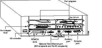
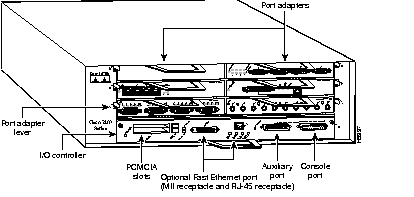
The port adapters installed in the Cisco 7200 series routers are of the same type as those installed on the second-generation Versatile Interface Processors (VIP2s) in the Cisco 7500 series routers, and in Cisco 7000 series routers using the 7000 Series Route Switch Processor (RSP7000) and 7000 series Chassis Interface (RSP7000CI). The port adapters installed in the Cisco 7200 series routers support online insertion and removal (OIR).
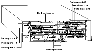
Port adapter slots in the Cisco 7200 series are numbered from the lower left to the upper right, beginning with port adapter slot 1 and continuing through port adapter slot 4 for the Cisco 7204, and slot 6 for the Cisco 7206. Port adapter slot 0 is the optional Fast Ethernet port on the I/O controller. Figure 3 shows the port adapter slot numbering for the Cisco 7206.
The rear of the Cisco 7200 series routers provides access to a network processing engine and up to two 280W, AC-input or DC-input power supplies (refer to Figure 4).
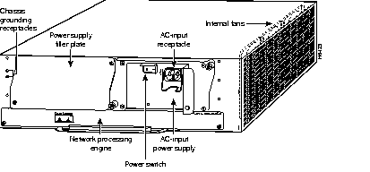
The network processing engine has no external connectors or LEDs. There are two handles for removing and installing the network processing engine and two captive installation screws for securing it to the chassis.
A fully configured Cisco 7200 series router operates with only one installed power supply; however, a second, optional power supply of the same type provides hot-swappable, load-sharing, redundant power. The power supply has the router's main power switch and either an AC-input power receptacle, or three hardwired DC-input power leads (depending on the type of installed power supply). Adjacent to the power supply bays there are two chassis grounding receptacles that provide a chassis ground connection for ESD equipment or a grounding wire (refer to Figure 4).
Three internal fans draw cooling air into the chassis interior and across internal components to maintain an acceptable operating temperature (refer to Figure 4). The three fans are enclosed in a tray that is located in the subchassis.
The I/O controller, port adapters, power supplies, and network processing engine slide into their respective chassis slots and connect directly to the router's midplane; there are no internal cables to connect. The midplane distributes DC power from the power supplies to the I/O controller, port adapters, fan tray, and network processing engine.
The Cisco 7200 series subchassis, shown in Figure 5, has one slot for the network processing engine, two bays for up to two 280W AC-input or two 280W DC-input power supplies, and one slot for the fan tray. The subchassis also houses the router midplane. To replace the router midplane, you must replace the entire subchassis. The fan tray, network processing engine, and AC-input and DC-input power supplies are field-replaceable units (FRUs), which means they can be replaced independently of the subchassis.
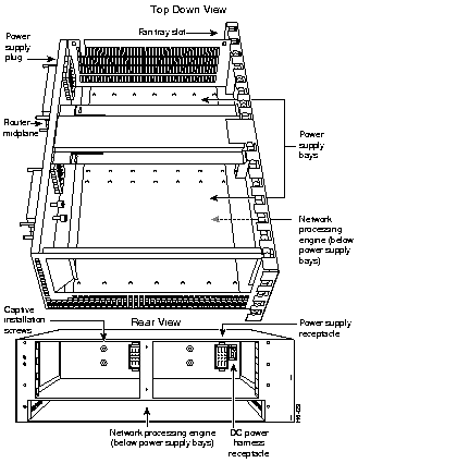
The fan tray, shown in Figure 6, consists of three fans enclosed in a metal case. The fan tray is located on the right side of the router when viewing the router from the rear (refer to Figure 4). The fan tray receives DC-input power through a power harness that connects to the router midplane.

The fan tray draws cooling air in through the intake vent on the right side of the chassis (when viewing the router from the front [the port adapter end]), and moves the air across the internal components and out the exhaust vent on the left side of the chassis. Figure 7 shows the air flow through the router.
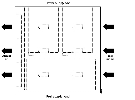
The left and right sides of the router must remain unobstructed to ensure adequate airflow and to prevent overheating inside the router. Maintain at least three inches of clearance on both sides of the router.
This section provides a list of parts and tools you need to remove and replace the subchassis and fan tray in the Cisco 7200 series routers. This section also includes safety and ESD-prevention guidelines to help you avoid injury to yourself and damage to the equipment.
You need the following tools and parts to remove and replace the subchassis and fan tray. If you need additional equipment, contact a service representative for ordering information.
Following are safety guidelines that you should follow when working with any equipment that connects to electrical power or telephone wiring.
Follow these basic guidelines when working with any electrical equipment:
Use the following guidelines when working with any equipment that is connected to telephone wiring or to other network cabling:
Electrostatic discharge (ESD) damages equipment and impairs electrical circuitry. ESD occurs when printed circuit boards are improperly handled and results in complete or intermittent failures.
The I/O controller, network processing engine, and port adapters consist of a printed circuit board that is fixed in a metal carrier. Electromagnetic interference (EMI) shielding, connectors, and a handle are integral components of the carrier. Handle the I/O controller, network processing engine, and port adapters by their carrier edges and handle; never touch the printed circuit board or connector pins.
Figure 8 shows how to handle the I/O controller and the network processing engine.

Figure 9 shows how to handle a port adapter.

Although the metal carrier helps to protect the printed circuit boards from ESD, wear a preventive antistatic strap whenever handling the I/O controller, network processing engine, or port adapters. Ensure that the strap makes good skin contact and connect the strap's clip to an unpainted chassis surface to safely channel unwanted ESD voltages to ground.
If no wrist strap is available, ground yourself by touching the metal part of the chassis.
Following are guidelines for preventing ESD damage:
 | Caution Periodically check the resistance value of the antistatic strap. The measurement should be within the range of 1 and 10 megohms. |
If your Cisco 7200 series router is installed in a standard 19-inch four-post or Telco rack, cables from other equipment in the rack may obstruct access to the rear of the router. Also, rack power strips or other permanent fixtures may obstruct access to the router. Review the following guidelines to ensure easy access to the rear of the router when it is installed in a rack. If the router is not installed in a rack, or if you already have clear access to the rear of the router, proceed to the following section "Removing and Replacing the Subchassis and Fan Tray."
Use the following guidelines to ensure easy access to the rear of the router when it is installed in a rack:
 | Caution Make sure that at least one other person is available to support the front of the router as you slide it out from the rack and, if necessary, to continue to support it while you remove and insert the power supply, network processing engine, or subchassis. |
Removing and replacing the subchassis and fan tray in the Cisco 7200 series routers involves the following tasks:
These tasks are described in detail in the following subsections.
To power down a Cisco 7200 series router, complete the following steps:
Step 1 Facing the rear of the router, place the power switch (on the power supply) in the OFF (0) position. Repeat this action if a second power supply is installed in the router.
Step 2 Observe the following items:
To disconnect AC-input power to a Cisco 7200 series router, complete the following steps:
Step 1 Unplug the input power cable from the power source.
Step 2 Push down on the cable-retention clip that secures the input power cable to the router's power supply.
Step 3 Unplug the other end of the input power cable from the power supply (refer to Figure 10).
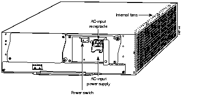
Step 4 Repeat Step 1 through Step 3 if a second power supply is installed.
To disconnect DC-input power to a Cisco 7200 series router, complete the following steps:
 | Warning Before completing any of the following steps, and to prevent short-circuit or shock hazards, ensure that power is removed from the DC circuit. To ensure that all power is OFF, locate the circuit breaker on the panel board that services the DC circuit, switch the circuit breaker to the OFF position, and tape the switch handle of the circuit breaker in the OFF position. |
 | Warning When installing the unit, the ground connection must always be made first and disconnected last. |
Step 1 Turn off the power source and disconnect the -48V and +48V leads from the power source. You can leave the ground cable connected.
Step 2 Remove the cable tie that secures the -48V, +48V, and ground leads to the power supply faceplate. Save the cable tie.
Step 3 Using a 3/16-inch flat-blade screwdriver, loosen the screw below the +48V lead receptacle and pull the lead from the connector (refer to Figure 11).
Step 4 Using the same screwdriver, loosen the -48V lead receptacle screw and pull the lead from the connector. Repeat Step 4 for the ground lead.
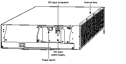
Step 5 Repeat Step 1 through Step 4 if a second power supply is installed.
This completes the procedure for powering down the router and disconnecting input power. Proceed to the following section "Removing a Power Supply and the Network Processing Engine."
The following sections explain how to remove an AC-input or DC-input power supply and the network processing engine from a Cisco 7200 series router. The power supply and the network processing engine reside in the subchassis; therefore, you must remove them before you remove the subchassis from the router.
The steps for removing an AC-input and DC-input power supply from a Cisco 7200 series router are the same. The two power supplies share the same dimensions and faceplates, except for the AC-input receptacle on the AC-input power supply and the DC-input lead receptacles on the DC-input power supply. To remove an AC-input or DC-input power supply from a Cisco 7200 series router, complete the following steps:
Step 1 Ensure that the power switch on the power supply is in the OFF (0) position and AC input power is disconnected from the power supply and its power source. (Refer to the section "Powering Down the Router and Disconnecting Input Power" earlier in this document.)
Step 2 Using a number 2 Phillips screwdriver, loosen the two captive screws on the faceplate of the power supply (refer to Figure 12).
If the router is not installed in a standard four-post or Telco rack, skip to Step 6. If the router is installed in a rack, determine if any permanent rack fixtures, such as a power strip, are obstructing access to the power supply. If a rack fixture is obstructing access to the power supply, proceed to Step 3.
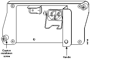
Step 3 Using a 3/16-inch flat-blade screwdriver, loosen the screws that secure the router to the front mounting strips of the rack.
Step 4 Position at least one person in front of the rack to support the front underside of the router.
Step 5 From the rear of the rack, carefully push the front of the router out of the rack until there is enough clearance to remove the power supply.
Step 6 Grasp the power supply handle and pull the power supply from the router.
 | Caution To maintain agency compliance requirements and meet EMI emissions standards for the Cisco 7200 series chassis with a single power supply, the power supply filler plate must remain in the power supply adjacent to the installed power supply. Do not remove this filler plate from the router unless you intend to install a redundant power supply. |
Step 7 Repeat Step 1 through Step 6 for the other installed AC-input power supply (if present).
This completes the procedure for removing an AC-input or DC-Input power supply from a Cisco 7200 series router. Proceed to the following section "Removing the Network Processing Engine."
To remove the network processing engine from a Cisco 7200 series router, complete the following steps:
Step 1 Attach an ESD-preventative wrist strap between you and an unfinished chassis surface.
Step 2 Using a number 2 Phillips screwdriver, loosen the two captive installation screws on the faceplate of the network processing engine (refer to Figure 13).
Step 3 Grasp the two network processing engine handles and carefully pull the network processing engine from its chassis slot.
 | Caution Handle the network processing engine by the carrier edges and handles only; never touch the printed circuit board components or connector pins (refer to Figure 8). |
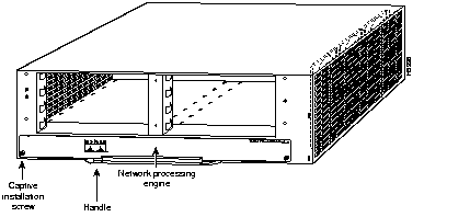
Step 4 Place the network processing engine on an antistatic surface with its components facing upward, or in a static shielding bag.
This completes the procedure for removing the network processing engine. Proceed to the following section "Disengaging the Input/Output Controller and the Port Adapters."
The following sections explain how to disengage the port adapters and I/O controller from the router midplane. The I/O controller and the port adapters are not located in the subchassis; therefore, you do not have to remove them from the router when removing the subchassis. However, the I/O controller and the port adapters connect directly to the router midplane, so you must disengage them from the router midplane to remove the subchassis from the router.
To disengage a port adapter from the router midplane, complete the following steps:
Step 1 Attach an ESD-preventative wrist strap between you and an unfinished chassis surface.
Step 2 Move the port adapter lever to the unlocked position (Figure 14).
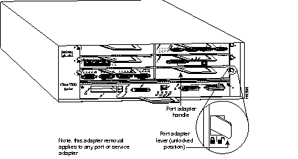
Step 3 Grasp the handle on the port adapter.
Step 4 With the port adapter lever in the unlocked position, pull the port adapter from the midplane about half way out of its slot. Do not remove the port adapter from the slot (refer to Figure 15).
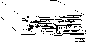
Step 5 Repeat Step 3 through Step 4 for each port adapter that is installed in the router.
This completes the procedure for disengaging a port adapter from the router midplane. Proceed to the following section "Disengaging the Input/Output Controller."
To disengage the I/O controller from the router midplane, complete the following steps:
Step 1 Attach an ESD-preventative wrist strap between you and an unfinished chassis surface.
Step 2 Using a number 2 Phillips screwdriver, loosen the two captive installation screws on the faceplate of the I/O controller.
Step 3 Grasp the handle on the I/O controller and pull the controller from the midplane about half way out of its slot (refer to Figure 16).
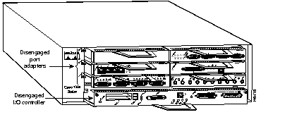
This completes the procedure for disengaging the I/O controller from the router midplane. Proceed to the following section "Removing the Subchassis."
To remove the subchassis from a Cisco 7200 series router, complete the following steps:
Step 1 Using a number 2 Phillips screwdriver, reach into a power supply bay and loosen the four subchassis captive installation screws (refer to Figure 17).
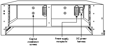
Step 2 Place one hand on the subchassis center post and your other hand on top of the router, and pull the subchassis from the router (refer to Figure 18).
The subchassis fits tightly in the router. Be prepared to use your hand on top of the router for leverage.
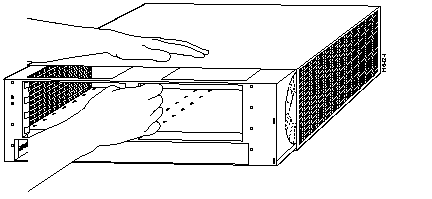
This completes the steps for removing the subchassis. Proceed to the following section "Removing the Fan Tray from the Subchassis."
To remove the fan tray from the subchassis, complete the following steps:
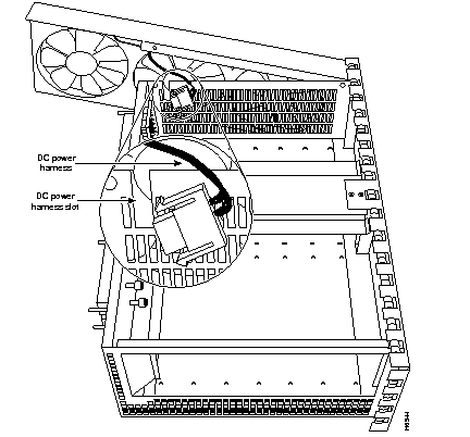
Step 1 Disconnect the fan tray's DC power harness from the router midplane. (Squeeze the DC connector while pulling it from the midplane.) (Refer to Figure 19.)
Step 2 Using a number 2 Phillips screwdriver, remove the two screws that secure the fan tray to the subchassis (refer to Figure 19). Save the screws.
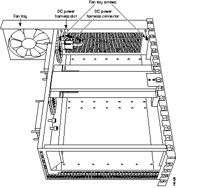
Step 3 Grasp the fan tray with one hand and the subchassis with the other hand.
Step 4 In one motion, rock the fan tray backward slightly to disengage it from the subchassis wall, then pull the fan tray upward to remove it from the subchassis (refer to Figure 20).
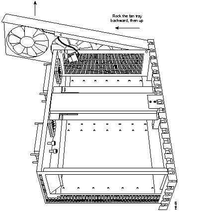
This completes the steps for removing the fan tray from the subchassis.
Proceed to the following section "Installing a New Fan Tray in the Subchassis."
To install a new fan tray in the subchassis, complete the following steps:
Step 1 Orient the fan tray so the fans face the subchassis and the DC power harness is at the top of the fan tray (refer to Figure 21).
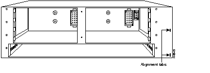
Step 2 Guide the fan tray into the subchassis making sure the DC power harness rests in its subchassis slot and the fan tray teeth mate with the subchassis wall.
Figure 22 shows the fan tray teeth mated with the subchassis wall.
Step 3 Secure the fan tray to the subchassis using the screws you saved when removing the fan tray (refer to Figure 23).
Step 4 Connect the DC power harness to the midplane.

This completes the steps for installing a new fan tray in the subchassis. Proceed to the following section "Replacing the Subchassis."
To replace the subchassis in the router, complete the following steps:
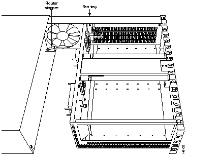
Step 1 Align the fan tray between the router stopper and the chassis wall (refer to Figure 24).
Step 2 Carefully slide the subchassis into the router until the subchassis is flush with the rear panel of the router. You may have to shift the subchassis a little to get it into the router.
Step 3 Using a number 2 Phillips screwdriver, reach into a power supply bay and tighten the subchassis captive installation screws (refer to Figure 25).

This completes the steps for replacing the subchassis in the router. Proceed to the following section "Replacing the Network Processing Engine and Power Supply."
The following sections explain how to replace the network processing engine and an AC-input or DC-input power supply in a Cisco 7200 series router.
To replace the network processing engine in the router, complete the following steps:
Step 1 Attach an ESD-preventative wrist strap between you and an unfinished chassis surface.
Step 2 Using both hands, grasp the network processing engine by its metal carrier edges and orient the network processing engine so that its printed circuit board components are upward (refer to Figure 8).
 | Caution Always handle the network processing engine by the carrier edges and handles only; never touch the printed circuit board components or connector pins. |
Step 3 Align the left and right edge of the network processing engine printed circuit board between the guides in the network processing engine slot (refer to Figure 26).
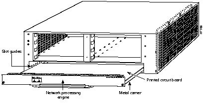
 | Caution Do not align the network processing engine's metal carrier between the slot guides. Doing so will damage components on the network processing engine's printed circuit board as you slide the network processing engine into its chassis slot. |
Step 4 Gently slide the network processing engine all the way into its slot until you feel the connectors mate with the midplane.
Step 5 Seat the network processing engine in the midplane by tightening its captive screws with a number 2 Phillips screwdriver.
This completes the procedure for installing the network processing engine. Proceed to the following section "Replacing an AC-Input or DC-Input Power Supply."
To install an AC-input or DC-input power supply in a Cisco 7200 series router, complete the following steps:
Step 1 Make sure the power switch on the power supply is in the OFF (0) position.
Step 2 Grasp the power supply handle with one hand and place your other hand underneath the power supply for support (refer to Figure 27).
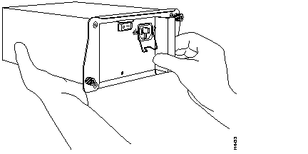
Step 3 Align the power supply to the power supply bay.
Step 4 Slide the power supply completely in to the power supply bay until its faceplate is flush with the router's rear panel.
 | Caution When inserting a power supply into the router, do not use unnecessary force; slamming the power supply into the bay can damage the connectors on the rear of the supply and on the midplane. |
Step 5 Seat the power supply in the router by tightening its captive screws with a number 2 Phillips screwdriver.
Step 6 Repeat Step 1 through Step 5 for a second power supply (if present).
Step 7 If there is no second power supply, replace the filler plate on the empty power supply bay. Using a number 2 Phillips screwdriver, tighten the filler plate's captive screws.
Step 8 If you pushed the router from the rack, slowly guide the router back into the rack.
Step 9 Use a 3/16-inch flat-blade screwdriver to tighten the screws that secure the router to front mounting strips of the rack.
 | Caution To maintain agency compliance requirements and meet EMI emissions standards for the Cisco 7200 series routers with a single power supply, the power supply filler plate must remain in the power supply adjacent to the installed power supply. Do not remove this filler plate from the router unless you intend to install a redundant power supply. |
This completes the procedures for replacing an AC-input or DC-input power supply in a Cisco 7200 series router. Proceed to the following section "Reseating the I/O Controller and the Port Adapters."
The following sections explain how to reseat the I/O controller and port adapters that you disengaged from the router midplane earlier in these procedures.
Complete the following steps to reseat the I/O controller:
Step 1 Attach an ESD-preventative wrist strap between you and an unfinished chassis surface (if necessary).
Step 2 Make sure the left and right edges of the I/O controller's printed circuit board are aligned between the guides in its slot.
 | Warning Do not align the I/O controller metal carrier between the guides in the slot. Doing so will damage components on the I/O controller's printed circuit board as you slide the I/O controller into its chassis slot. |
Step 3 Using both hands, grasp the I/O controller by its metal carrier edges and gently slide the controller all the way into its slot until you feel the connectors mate with the midplane.
Step 4 Seat the I/O controller in the midplane by tightening its captive screws with a number 2 Phillips screwdriver.
This completes the procedure for reseating an I/O controller. Proceed to the following section "Reseating the Port Adapters."
Complete the following steps to reseat the port adapters:
Step 1 Attach an ESD-preventative wrist strap between you and an unfinished chassis surface (if necessary).
Step 2 With the port adapter still in the unlocked position, grasp the handle on the port adapter and gently push the port adapter all the way into its slot until you feel the connectors mate with the midplane.
Step 3 Move the port adapter lever to the locked position. Figure 28 shows the port adapter lever in the locked position. Repeat this step for each port adapter installed in the router.
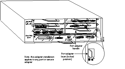
This completes the procedure for reseating a port adapter. Proceed to the following section "Reconnecting Input Power and Powering Up the Router."
The following procedures explain how to reconnect AC-input and DC-input power to a Cisco 7200 series router, power up the router, and verify a successful system boot.
To reconnect AC-input power to a Cisco 7200 series router, complete the following steps:
Step 1 At the rear of the router, check that the power switch on the power supply is in the OFF (0) position.
Step 2 Slide the cable-retention clip down, away from the AC receptacle, and plug in the power cable.
Step 3 Secure the cable in the power supply AC receptacle by sliding the cable-retention clip up until it snaps around the connector. The cable-retention clip provides strain relief for the AC power cable (refer to Figure 29).
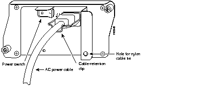
Step 4 Plug the AC power supply cable into the AC power source.
Step 5 Repeat Step 1 through Step 4 if a second power supply is installed.
This completes the steps for reconnecting AC-input power to a Cisco 7200 series router.
To reconnect DC-input power to a Cisco 7200 series router, complete the following steps:
 | Warning Before completing any of the following steps, and to prevent short-circuit or shock hazards, ensure that power is removed from the DC circuit. To ensure that all power is OFF, locate the circuit breaker on the panel board that services the DC circuit, switch the circuit breaker to the OFF position, and tape the switch handle of the circuit breaker in the OFF position. |
 | Warning When installing the unit, the ground connection must always be made first and disconnected last. |
Step 1 Ensure that the -48V and +48V leads are disconnected from the power source.
Step 2 If necessary, use a wire stripper to strip approximately .55 inch (14 mm) from the -48V, +48V, and ground leads (refer to Figure 30).

Step 3 At the rear of the router, check that the power switch on the power supply is in the OFF (0) position (refer to Figure 11).
Step 4 Insert the stripped end of the ground lead all the way into the ground lead receptacle on the DC-input power supply and tighten the receptacle screw using a 3/16-inch flat-blade screwdriver (refer to Figure 31).
Step 5 Insert the stripped end of the +48V lead all the way into the +48V lead receptacle and tighten the receptacle screw using the same 3/16-inch flat-blade screwdriver. Repeat Step 5 for the -48V lead.
Step 6 After tightening the receptacle screw for the ground, +48V, and -48V DC-input leads, use the cable tie you saved earlier in this procedure to secure the three leads to the power supply faceplate.
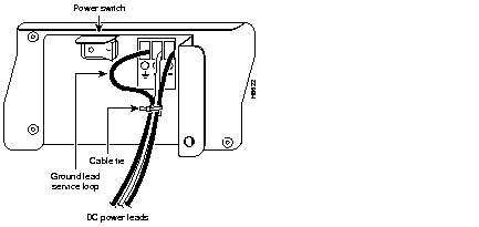
Step 7 Connect the ground, +48V, and -48V leads to the power source.
Step 8 Repeat Step 1 through Step 7 if a second power supply is installed.
This completes the steps for connecting input power to a Cisco 7200 series router.
To power up a Cisco 7200 series router that has an installed AC-input or DC-input power supply, complete the following steps:
Step 1 Check for the following:
Step 2 At the rear of the router, place the power switch on the power supply in the ON (|) position. Repeat this step if a second power supply is installed in the router. The green OK LED on the power supply turns on.
Step 3 Listen for the fans; you should immediately hear them operating.
Step 4 During the boot process, observe the system's LEDs. The LEDs on most of the port adapters go on and off in irregular sequence. Some may go on, go out, and go on again for a short time. On the I/O controller, the IO Power OK LED comes on immediately.
Step 5 Observe the initialization process. When the system boot is complete (a few seconds), the network processing engine begins to initialize the port adapters and the I/O controller. During this initialization, the LEDs on each port adapter behave differently (most flash on and off). The enabled LED on each port adapter goes on when initialization is completed, and the console screen displays a script and system banner similar to the following:
This completes the procedures for connecting input power and powering up the router. This also completes the procedure for replacing the subchassis and fan tray in a Cisco 7200 series router.


|
|