|
|

This chapter introduces the Catalyst 1900 series Ethernet switches and covers the following topics:
The Catalyst 1900 series Ethernet switches--also referred to as the Catalyst 1900 switches--are designed for large and small Ethernet workgroups and individual users requiring increased performance and 100-Mbps connectivity to servers and backbones. All of the Catalyst 1900 switches are members of an extended network system of stackable, modular LAN and WAN products that increase LAN performance, connect remote offices and users, and provide secure access.
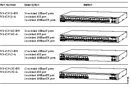
Table 1-1 describes the switches and provides an illustration of each model. Table 1-2 summarizes the key features that are common to all Catalyst 1900 switches.

| Feature | Description |
|---|---|
| Performance and Configuration |
|
| |
| |
| |
| |
| |
| |
| |
| Management |
|
| |
| |
| Redundancy |
|
The front panel of the switches provides 10BaseT and 100BaseT switched ports, a set of LEDs, and a Mode button.
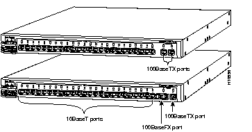
The front of each switch provides switched 10BaseT and 100BaseT ports (see Figure 1-1).

Depending on the model, the front panel of the switch has either 12 or 24 fixed 10BaseT ports, which are compatible with the IEEE 802.3 10BaseT standard. These ports
(1x through 12x or 1x through 24x) use standard RJ-45 connectors and can be connected to 10BaseT-compatible devices, such as individual workstations and hubs, with Category 3, 4, or 5 UTP cabling. Attached devices must be within 100 meters of the switch.
The default setting for these ports is half-duplex mode. You can configure these ports for full-duplex operation by using the management console (see the "Port Configuration Menu" section in the "Configuration and Management" chapter) or by using SNMP.
For information on connecting from these ports, see the "Connecting to the 10BaseT Ports" section in the "Installation" chapter.
Depending on the model, the switch can have either:
The 100BaseTX ports (ports Ax and Bx) are compatible with the IEEE 802.3u 100BaseTX specifications and can connect to 100BaseTX-compatible servers, hubs, backbone switches, and routers. Connecting to the 100BaseTX ports requires Category 5 UTP cabling. Devices must be within 100 meters of the 100BaseTX port on the switch.
The 100BaseTX ports support IEEE 802.3x standards-based flow control when operating in full-duplex mode. If the port is configured for full-duplex operation, you can provide up to 200 Mbps of bandwidth between the switch and the connected device. The default setting for the 100BaseTX ports is autonegotiation-enabled. Autonegotiation is supported on the 100BaseTX ports only. You can configure these ports for full-duplex or half-duplex operation or allow autonegotiation to determine the optimum configuration.
The 100BaseFX port (port A) is compatible with the IEEE 802.3u 100BaseFX specification and can connect to other 100BaseFX-compatible devices. This port uses 50/125- or 62.5/125-micron multimode fiber-optic cabling.
The default setting for the 100BaseFX port is half-duplex mode, but you can configure this port for full-duplex mode. Autonegotiation is not available on this port. If the 100BaseFX port is configured for full-duplex operation, you can connect it to another 100BaseFX-compatible device over distances of up to 2 kilometers and provide up to
200 Mbps of bandwidth between the two devices. If the port is configured for half-duplex operation, you can connect the port to another device that is within 412 meters of the switch.
| Port | Duplex Mode | Cable | Cable Distance |
|---|---|---|---|
| 100BaseTX | Autonegotiation (default) Full duplex with flow control Full duplex Half duplex | Category 5 UTP | 100 m (half duplex or full duplex) |
| 100BaseFX | Full duplex with flow control Full duplex Half duplex (default) | 50/125- or 62.5/125-micron multimode fiber-optic | 412 m (half duplex)
2 km (full duplex) |
You can configure these ports by using the management console (see the "Port Configuration Menu" section in the "Configuration and Management" chapter) or by using SNMP. For information on connecting from these ports, see the "Connecting to the 100BaseTX Ports" and "Connecting to the 100BaseFX Port" sections in the "Installation" chapter.
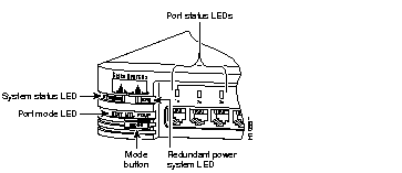
You can use the LEDs on the switch to monitor network activity and performance. Figure 1-2 shows the location of the LEDs and the Mode button, which you use to select the modes indicated by the port mode LED.

The system status (SYSTEM) LED indicates whether the switch is receiving power and functioning properly. Table 1-3 provides a description of the LED colors and their meanings.
| Color | System Status |
|---|---|
| Off | Switch is not powered up. |
| Solid green | Switch is operating normally. |
| Solid amber | Switch is receiving power but might not be functioning properly. One or more non-fatal power-on self-test (POST) errors occurred. Refer to the Management Console Logon Screen for the message identifying which POST test(s) failed. |
The redundant power system (RPS) LED shows the RPS status. Table 1-4 provides a description of the LED colors and their meanings.
| Color | RPS Status |
|---|---|
| Off | Power is OK (internal power supply is powered up). |
| Solid green | Power is OK (RPS is powered up and operational). |
| Solid amber | RPS is connected but not operational. |
| Flashing green | RPS and internal power supply are both powered up. Only one power source can be supplying power to the switch.
If you are using the RPS, the AC power cord of the switch must not be plugged in. If you are using the internal power supply, the RPS can be connected but must be powered down. |
The port mode LED indicates the mode you selected using the Mode button:
The port status LEDs--located above the 10BaseT, 100BaseTX, and 100BaseFX ports--indicate the status of each individual port.
To change the mode being displayed by a port status LED, press the Mode button to highlight in sequence each of the modes: STAT (port status), UTL (bandwidth utilization), and FDUP (full-duplex status). When the desired mode is selected, release the button to make the change. As long as you hold the Mode button down, the mode does not change. The selected mode remains on for 30 seconds before returning to the default mode selected through the Console Settings Menu.
In port status (STAT) mode, each port status LED indicates the status of the individual port. Table 1-5 provides a description of the LED colors and their meanings.
| Color | Port Status |
|---|---|
| Off | No link. |
| Solid green | Link operational (with no link activity). |
| Flashing green | Link operational (with activity). |
| Alternating green and amber | Link fault. Error frames can affect connectivity, and errors such as excessive collisions, CRC errors, and alignment and jabber errors are monitored for a link-fault indication. |
| Solid amber | Port is not forwarding. For example, this could be because the port was disabled by management, suspended due to an address violation, or suspended by Spanning-Tree Protocol due to the presence of network loops. |
In utilization (UTL) mode, the port status LEDs show the current and peak bandwidth utilization of the switch. Current bandwidth is shown with a series of lit port status LEDs ending with a rapidly blinking one. Peak bandwidth is indicated by the right-most solidly lit LED.
The peak utilization is recorded in the bandwidth-capture interval. For information on how to change the bandwidth-capture interval, see the "Bandwidth Usage Report" section in the "Configuration and Management" chapter.
Table 1-6 shows the bandwidth utilization scale for the switch with 12 10BaseT ports and 24 10BaseT ports.
| 12 10BaseT Ports | 24 10BaseT Ports | ||
|---|---|---|---|
| Port Status LEDs | Mbps Activity | Port Status LEDs | Mbps Activity |
| 1 to 4 | 0.1 to < 1.5 | 1 to 8 | 0.1 to < 6 |
| 5 to 8 | 1.5 to < 20 | 9 to 16 | 6 to < 120 |
| 9 to 12 | 20 to 140 | 17 to 24 | 120 to 280 |
In full-duplex status (FDUP) mode, the port status LEDs indicate which port is operating in full-duplex mode. All 10BaseT and 100BaseT ports on the switches support full-duplex operation. Table 1-7 provides a description of the LED colors and their meanings.
| Color | Full-Duplex Status |
|---|---|
| Off | Half-duplex mode is operational. |
| Solid green | Full-duplex mode is operational. |
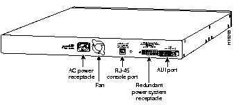
The rear panel of the switches provides an AC power receptacle, an RJ-45 console port, a redundant power system (RPS) receptacle, and an AUI port (see Figure 1-3).

You can provide power to the switch either by using the internal power supply or by connecting the Cisco RPS to the RPS receptacle on the switch. Only one power source can be supplying power to the switch.
If you want to use the internal power supply, which is an autoranging unit supporting input voltages of 90 to 127/200 to 250 VAC, use the supplied AC power cord to connect the AC power receptacle to an AC power outlet.
If you want to use the RPS, the supplied AC power cord must not be plugged in. See the Cisco RPS documentation for detailed information on connecting to the RPS.
 | Warning Use only the Cisco RPS (model PWR600-AC-RPS-CAB/ PWR600-AC-RPS-NCAB) to power your unit with the RPS receptacle. |
You can configure and manage the switch through the management console by connecting the console port on the switch to a terminal or modem. The switch is supplied with the RJ-45-to-RJ-45 rollover cable and adapters you need to properly connect to a terminal or modem.
For additional information on connecting from this port, see the "Connecting to the Console Port" section in the "Installation" chapter.
You can connect an external transceiver to the AUI port on the switch by using thick coaxial, thin coaxial, or fiber-optic cable. Supported network and device distances vary depending on the type of transceiver used.
For additional information on connecting from this port, see the "Connecting to the AUI Port" section in the "Installation" chapter.
This section provides following examples of how the Catalyst 1900 switches can be used in your network:
In Figure 1-4, a Catalyst 1900 switch supports up to 25 switched (dedicated) Ethernet connections to workstations or 10BaseT hubs. Each workstation or hub directly connected to a port on the switch has a dedicated bandwidth of 10 Mbps. However, all the workstations connected to the 10BaseT hub or repeater share the 10 Mbps of bandwidth.
The two 100-Mbps servers are connected to the 100BaseTX ports on the switch. If these ports are configured for full-duplex operation, each port can provide a total of 200 Mbps bandwidth between each server. These servers are accessible to all the users in the workgroup.

In Figure 1-5, three Catalyst 1900 switches are connected to each other through their 100-Mbps ports. The switches, depending on the model, support 12 or 24 switched 10BaseT connections for single workstations or 10BaseT hubs. You can use the 100BaseTX ports or the 100BaseFX port to connect to servers and switches. If these ports are configured for full-duplex operation, they can provide a total of 200 Mbps bandwidth on each port.

You can create a 100-Mbps collapsed backbone by connecting Catalyst 1900 switches to a 100BaseT backbone switch or router, as shown in Figure 1-6. In this example, two Catalyst 1900 switches are connected to a Catalyst 5000 switch or Cisco 7000 router through 100BaseT ports in CollisionFree full-duplex mode, allowing up to 200 Mbps of bandwidth to both Catalyst 1900 switches. In addition, the distance between each Catalyst 1900 switch and the backbone switch or router can be increased to up to
2 kilometers by using fiber-optic cabling.

You can create a 100BaseT redundant backbone network by connecting Catalyst 1900 switches to 100BaseT backbone switches or routers, as shown in Figure 1-7. In this example, each Catalyst 1900 switch is connected to the two Catalyst 5000 switches or Cisco 7000 routers, shown at the top-left and top-right corners, in a redundant configuration. If connectivity is lost to one of the backbone routers or switches, the network then uses the redundant connection to keep the devices working.
In addition, Spanning-Tree Protocol, available only on the switches, ensures that only one of the two connections from each switch is active (the primary link), ensuring that there are no loops in the network paths between any two end nodes. If the primary link fails, the secondary link automatically becomes active.
The Catalyst 1900 switches in this example are connected to the backbone switches or routers through the 100BaseT ports in CollisionFree full-duplex mode. This allows both links to support up to 200 Mbps of bandwidth to each backbone switch or router. To support full-duplex operation on the 100-Mbps port connected to the router, you must install a network interface card (NIC) that supports 100-Mbps full-duplex operation in the router. In addition, the distance between each Catalyst 1900 switch and the backbone switch or router can be increased to up to 2 kilometers by using a fiber-optic cable.

A system of routers, switches, and hubs can be combined to create a high-performance network that extends beyond the main office LAN to connect to branch offices, remote sites, mobile users, and the Internet. Figure 1-8 is an application for an extended network system.

|
|