|
|

This chapter provides the following information:
Information about installing the Catalyst 2820 modules is provided in the Catalyst 2820 Modules User Guide and the Catalyst 2820 ATM Modules Installation and Configuration Guide.
Translated versions of the following safety warnings are provided in the "Translated Safety Warnings" appendix.
 | Warning Only trained and qualified personnel should be allowed to install or replace this equipment. |
| Warning Do not work on the system or connect or disconnect cables during periods of lightning activity. |
Warning
Unplug the power cord before you work on a system that does not have an on/off switch.
| Warning Do not touch the power supply when the power cord is connected. For systems with a power switch, line voltages are present within the power supply even when the power switch is off and the power cord is connected. For systems without a power switch, line voltages are present within the power supply when the power cord is connected. |
| Warning Read the installation instructions before you connect the system to its power source. |
| Warning This product relies on the building's installation for short-circuit (overcurrent) protection. Ensure that a fuse or circuit breaker no larger than 120 VAC, 15A U.S. (240 VAC, 10A international) is used on the phase conductors (all current-carrying conductors). |
| Warning To prevent the switch from overheating, do not operate it in an area that exceeds the maximum recommended ambient temperature of 113×F (45×C). To prevent airflow restriction, allow at least 3 inches (7.6 cm) of clearance around the ventilation openings. |
| Warning The device is designed to work with TN power systems. |
| Warning This equipment is intended to be grounded. Ensure that the host is connected to earth ground during normal use. |
| Warning When installing the unit, the ground connection must always be made first and disconnected last. |
| Warning Do not stack the chassis on any other equipment. If the chassis falls, it can cause severe bodily injury and equipment damage. |
| Warning Care must be given to connecting units to the supply circuit so that wiring is not overloaded. |
| Warning A voltage mismatch can cause equipment damage and may pose a fire hazard. If the voltage indicated on the label is different from the power outlet voltage, do not connect the chassis to that receptacle. |
| Warning Ultimate disposal of this product should be handled according to all national laws and regulations. |
When determining where to place the switch, ensure the following conditions are met:
Follow these steps to unpack the switch:
Step 1 Open the shipping container and carefully remove the contents.
Step 2 Return all packing materials to the shipping container and save it.
Step 3 Ensure that all items listed in the following section, "Package Contents," were included in the shipment. Check each item for damage.
Each switch is shipped with the following items:
To install the switch on a table or shelf, follow these steps:
Step 1 Locate the adhesive strip with the rubber feet that shipped with the switch.
Step 2 Place the switch on a level surface and attach the rubber feet to the four round recessed areas on the bottom corners of the switch.
Step 3 Place the switch on a table or shelf close to an AC power receptacle.
Step 4 Attach the AC power cord to the switch. If your configuration has an RPS, see the RPS documentation.
After power is connected, the switch automatically starts a series of self-tests described in the "Verifying Your Installation Using the Power-On Self-Test" section in this chapter.
This section describes how to install the switch in 19- and 24-inch standard and telco racks.
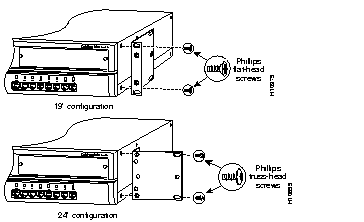
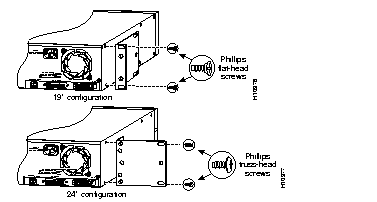
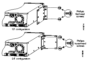
The bracket orientation and the screws you use depend on whether you are attaching the brackets for 19-inch or 24-inch rack-mounting:
Place the switch on a level surface, and use two of the supplied Phillips flat-head or truss-head screws to attach a mounting bracket to each side of the switch. Secure all four screws tightly, but do not overtighten them.
Figure 2-1, Figure 2-2, and Figure 2-3 show how to attach one bracket to one side of the switch. Follow the same steps to attach the second bracket to the opposite side of the switch.
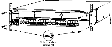
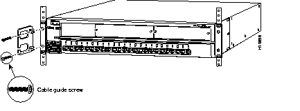
After the brackets are attached to the switch, use two of the supplied Phillips machine screws to securely attach each bracket to the rack, as shown in Figure 2-4.
If the switch is attached to a 19- or 24-inch rack, you can attach the cable guide to the left or right rack-mount bracket, using the supplied black screws, as shown in Figure 2-5. Attaching the cable guide is recommended to prevent the cables from obscuring the front panel of the switch and the components of other devices installed in the rack.
After you have installed the switch in the rack, attach the power cord to the switch. If your configuration has an RPS, see the RPS documentation.
After power is connected, the switch automatically starts a series of self-tests described in the "Verifying Your Installation Using the Power-On Self-Test" section in this chapter.
This section describes how to attach the switch in parallel and vertically to a wall.
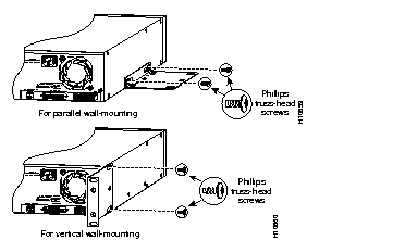
The bracket orientation depends on whether you are attaching the brackets for parallel or vertical wall-mounting:
Place the switch on a level surface, and use two of the supplied Phillips truss-head screws to attach a mounting bracket to each side of the switch. Secure all four screws tightly, but do not overtighten them.
Figure 2-6 shows how to attach only one bracket to one side of the switch. Follow the same steps to attach the second bracket to the opposite side of the switch.
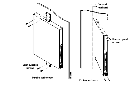
For the best support of the switch and cables, make sure the switch is securely attached to a wall stud or to a firmly attached plywood mounting backboard, as shown in Figure 2-7. You must supply your own screws to attach the switch to a wall.
After you have attached the switch to a wall, attach the power cord to the switch. If your configuration has an RPS, see the RPS documentation.
After power is connected, the switch automatically starts a series of self-tests described in the "Verifying Your Installation Using the Power-On Self-Test" section in this chapter.
After you install the switch and before you connect it to other network devices, you should power up the switch and run the power-on self-test (POST).
The switch automatically begins POST after you power up the switch. POST consists of 13 individual tests, as listed in Table 4-1. The port status LEDs indicate which POST test the switch is currently executing. As each POST test executes, a port status LED turns off. For example, if the LED for port 4x is off, it means the console port test (POST test 4) is being executed. The port status LED for port 16x turns off first, followed by ports 12x, 11x, 10x, and so on. The LEDs for ports 15x, 14x, 13x are not used during POST.
When POST completes, the following conditions can exist (assuming that other devices are not yet connected to the switch):
You should inform your system administrator if one or more nonfatal failures are detected during POST. Contact your Cisco sales representative if any fatal failures are detected.
The "Understanding POST Failures" section in the "Troubleshooting" chapter provides additional information about POST, including descriptions of the possible causes of nonfatal and fatal POST failures.
To manage the switch through the management console, you must use the RJ-45-to-RJ-45 rollover cable and the appropriate adapter (both supplied with the switch) to connect the RJ-45 console port of the switch to a management station or modem.
To connect the console port to a management station or modem, follow these steps:
Step 1 Configure the baud rate and character format of the management station or modem to match the following default physical characteristics of the console port:
Although the Match Baud Rate option (autobaud) matches the baud rate when the switch is answering an incoming call, the switch does not change from its configured rate when dialing out. It also only matches a rate lower than or equal to its configured rate. When a call is completed and the line disconnects, the switch always returns to its last configured baud rate.
You can change the console port characteristics of the switch by using the RS-232 Port Configuration Menu (see the "RS-232 Interface Configuration Menu" section in the "Configuration and Management" chapter). If you are using Simple Network Management Protocol (SNMP), these characteristics can be changed with the RS-232 MIB objects.
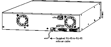
Step 2 Insert one end of the supplied rollover cable into the console port, as shown in Figure 2-8.
 | Caution Do not connect an actual telephone line, a live ISDN line, or an Ethernet cable to this console port. Damage to the switch can result. Make sure you use the supplied RJ-45-to-RJ-45 rollover cable and adapters to connect the console port to the management station or modem. |
Step 3 Attach one of the following supplied adapters to a management station or modem:
Step 4 Insert the other end of the supplied rollover cable into the adapter.
Step 5 From your management station, start up the terminal emulation program.
The Management Console Logon Screen (see Figure 3-2) is displayed when POST completes. For details on using the management console, see the "Configuration and Management" chapter. If the Management Console Logon Screen does not display, see the "Troubleshooting" chapter for assistance.
Connector and cabling specifications for the console port are in the "Connectors and Cables" appendix.
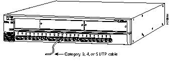
All 10BaseT RJ-45 ports (ports 1x through 24x) on the switch can connect to any 10BaseT-compatible device. You must provide the Category 3, 4, or 5 UTP cable(s) required for connecting any of these ports to other 10BaseT devices. All UTP connections between the switch and the attached device(s) must be within 100 meters.
The 10BaseT ports are internally crossed. When connecting the switch to servers and workstations, ensure that you use a straight-through cable wired for 10BaseT. When connecting to other switches or repeaters, ensure that you use a crossover cable.
The default setting for these ports is half-duplex mode. You can configure these ports for full-duplex operation by using the management console (see the "Port Configuration Menu" section in the "Configuration and Management" chapter) or by using SNMP. Full-duplex flow control is not supported on the 10BaseT ports.
To connect a 10BaseT port on the switch to another 10BaseT device, follow these steps:
Step 1 Insert one end of the UTP cable into the 10BaseT port on the switch, as shown in Figure 2-9.
Step 2 Insert the other end of the UTP cable into the 10BaseT port of the target device.
The port status LED comes on when both the switch and the connected device are powered up. If the port status LED does not come on, the device at the other end might not be turned on, there might be a problem with the adapter in the attached device or with the cable, or you might need to change the type of cable. See the "Troubleshooting" chapter for more information.
Step 3 Reconfigure and reboot the connected device as needed.
Step 4 Repeat steps 1 through 3 for each device that needs to be connected to the switch.
Connector and cabling specifications for the 10BaseT ports are in the "Connectors and Cables" appendix.
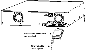
The AUI port on the switch can connect to an Ethernet transceiver, which is then connected to a 10-Mbps Ethernet device through thick coaxial, thin coaxial, fiber-optic, or UTP cable. You must provide the Ethernet transceiver and cable required to connect the AUI port to the other network device. Supported network and device distances vary depending on the type of Ethernet AUI transceiver used.
To connect the AUI port on the switch to an external transceiver, follow these steps:
Step 1 Attach the appropriate external transceiver to the AUI port on the switch.
Step 2 Insert one end of the appropriate cable into the port on the AUI transceiver, as shown in Figure 2-10. The type of cable (thick coaxial, thin coaxial, fiber-optic, or UTP) you use depends on the AUI transceiver you are using.
Step 3 Insert the other end of the cable into the port of the target device.
Step 4 Reconfigure and reboot the connected device as needed.
Connector and cabling specifications for the AUI port are in the "Connectors and Cables" appendix.
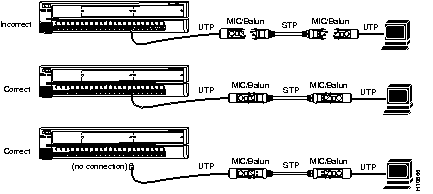
Shielded twisted-pair (STP) cable is the most commonly used cable in Token Ring environments. The media interface connectors (MICs) and baluns--used to connect STP and UTP cabling--create a loopback when they are disconnected; the loopback might cause anomalies with the switch.
To prevent loopback problems when using STP cabling in a Token Ring network environment, make sure the MICs and baluns are never left unconnected when they are part of a link connected to the switch (see Figure 2-11).
|
|