|
|

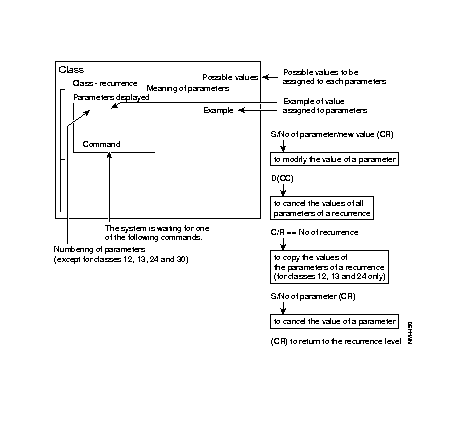
This section takes the form of data sheets describing the configuration.
These sheets give, for each class:
Figure 4-1 shows the lay out of a configuration data sheet.
General password to Configuration Function.
| C0 - R0 | Access key to configurator | ||
Parameters displayed |
Meanings of parameters |
Possible values | |
0 -------- | Password | Up to 8 alphanumeric characters.
Default Password: CCLAER | |
| C1 - R0 | Name, code, date of configuration | ||
Parameters displayed |
Meanings of parameters |
Possible values | |
0 -------- | Name of configuration Customer identification Date of modification of configuration | Up to 8 alphanumeric characters. Up to 8 alphanumeric characters. 6 characters and following format obligatory: DDMMYY. | |
| C1 - R1 | Use of lines | ||
Parameters displayed | Meanings of parameters | Possible values | |
0 -- | Parameters 0 to 35 correspond to 36 configurable lines. Parameters 36 to 41 are reserved. | "1" = line configured as X.25 synchronous "2" = line configured as asynchronous "4" = line configured as asynchronous SDLC "6" = line configured as asynchronous VIP character "7" = line configured as asynchronous BSC- Transparent character "8" = line configured as character asynchronous on BSC 3270 or 2780/3780 | |
| "14" = line configured as D-channel (ISDN) with or without PLL "15" = line configured as B-channel with signalling (ISDN) "16" = line configured as B-channel without signalling (ISDN) (subsequent upgrading) "19" = line configured as Frame relay Type transit (FRTE, FRSW) "20" = line configured as a HDLC line "21" = line configured as a Frame relay subscr. line (FRCE) "30" = line configured as asynchronous X.28+ | ||
The values "14" can ONLY be used for the line numbers 0, 3, 6, 9, 12, 15, 18, 21, 24, 27, 30 or 33.
The values "15" or "16" can NOT be used for the line numbers 0, 3, 6, 9, 12, 15, 18, 21, 24, 27, 30 or 33.
The values "23", "27" and "28" can be used only on LAN type lines (line 6) (LMX case).
Parameters to connect these lines are defined in C12 and C13.
| C1 - R2 | DNIC ZO No. of the equipment | ||
Parameters displayed | Meanings of parameters | Possible values | |
0 ------ COMMAND | Private-network address of equipment (FastPAD numbering). Reserved (1 byte). | 6 digits obligatory. | |
| C1 - R3 | Configuration version No. | ||
Parameters displayed | Meanings of parameters | Possible values | |
0 --- | Configuration counter. | Number automatically incremented by 1 each time configuration is modified (between 1 and 254). Return to 0 with default configuration change. | |
| C2 - R0 | Read-protected recurrences This recurrence is used to set up the read protection codes for certain classes and/or recurrences. | ||||
| Parameters displayed | Meanings of parameters | Possible values; Example | |||
| 0
1 5 | -,-,-,-,-,- -,-,-,-,-,- -,-,-,-,-,- -,-,-,-,-,- -,-,-,-,-,- -,-,-,-,-,- -,-,-,-,-,- -,-,-,-,-,- 0,0,1 -,-,-,-,-,- -,-,-,-,-,- 1 -,-,-,-,-,- -,-,-,-,-,- -,-,-,-,-,- -,-,-,-,-,- -,-,-,-,-,- -,-,-,-,-,- -,-,-,-,-,- | CLASS 0 CLASS 1 CLASS 2 CLASS 3 CLASS 4 CLASS 5 CLASS 6 CLASS 7 CLASS 8 CLASS 9 |
These parameters correspond to the classes having the same numbers that define the configuration. |
-,-,-,-,-,- | | | Nos. of protected recurrences in case of | partial protection | (up to 5 recurrences)
1 = class completely protected 0 = class partly protected if no recurrence number follows
| |
| 18 19 20 21 22 23 24 25 26 27 28 29 30 31 32 33 34 COMMAND | -,-,-,-,-,- -,-,-,-,-,- -,-,-,-,-,- -,-,-,-,-,- -,-,-,-,-,- -,-,-,-,-,- -,-,-,-,-,- -,-,-,-,-,- -,-,-,-,-,- -,-,-,-,-,- -,-,-,-,-,- -,-,-,-,-,- -,-,-,-,-,- -,-,-,-,-,- -,-,-,-,-,- -,-,-,-,-,- -,-,-,-,-,- -,-,-,-,-,- | CLASS 18 CLASS 19 CLASS 20 CLASS 21 CLASS 22 CLASS 23 CLASS 24 |
Example: Class 10, completely protected Class 7, only recurrences 0 and 1 are protected. The other classes are not protected. | ||
| C2 - R1 | Write-protected recurrences Same as C2 - R0 but the classes and/or recurrences are write-rather than read protected | |
| C2 - R2 | General system parameters | |
| Parameters displayed | Meanings of parameters | Possible values |
| 0 -- 1 -- 2 - 3 - 4 - 5 - 6 - 7 - | Number of lines configured Number of simultaneous calls Reserved DNIC supervision Maximum packet size Minimum packet size contacting of calling address on PDN Secured mode (FastPADmpr12) | 1 to 36 1 to 8 (modulo 256) * can not be configured can not be configured can not be configured 0 = contacting |
| 8 - 9 -- 10 - 11 - 15 COMMAND | Type of language Reserved Authorization with maximum number of TNIC Truncated address with 14 digits Zerf format Reserved Reserved | 0 = french, 1 = english 0 = no, 1 = yes 0 = reduced |
* (Modulo 32) for the FastPADmp6.
| C2 - R3 | Call parameters | ||
Parameters displayed | Meanings of parameters | Possible values | |
0 -- | Data frame rejection threshold Data frame acceptance threshold Call request packet rejection threshold Call request packet acceptance threshold Optimization behavior Local calls authorized Action toward unknown DNIC Action towards unknown ZO and/or AB Reserved | This values are percentages of the memory resources Simply type the desired percentages: 10, 20, ....up to 90 % 0 = Throughput class negotiation 1 = Has priority over packet window sizes 2 = Packet acknowledgment, on by one 0 = no, 1 = yes 0 = rejection, 1 = acceptance 1 = private type diag. cause 0 = public type diag cause 2 = X.75 diag. cause 0 = standard behavior 1 = transpac behavior | |
. . . 15- COMMAND | Reserved Reserved Reserved Reserved | ||
This class corresponds to the characteristics of each management function of the equipment.
| C3 - R0 | Traffic generator function | ||
Parameters displayed | Meanings of parameters | Possible values | |
0 -,--,--,------ | Characteristics of traffic generator function | -,--,--,------ | | | | | | | | | |
| | | | | | | | Password for access to funct|on | | | (up to 6 characters) (alphanumeric characters). | | | | | Traffic generator data packet | | transmission delay | | 0 = no time-out | | 1 to 98 = Transmission delay | | | ||
| C3 - R1 | Observation function | ||
Parameters displayed | Meanings of parameters | Possible values | |
0 -,------ | Characteristics of observation | -,------ | | | | | |
| | | Password for access to function | | (up to 6 alphanumeric characters) | | |___ 0 = function not configured 1 = function configured | ||
| C3 - R2 | Statistics function | ||
Parameters displayed | Meanings of parameters | Possible values | |
0 -,--,------ | Characteristics of statistics function | -,--,------ | | | | | | | |
| | | Password to access the function | | (up to 6 alphanumeric characters) | | | | | Statistics summing period, by | default unit = 10 seconds | possible values, 01 to 99 | 00 = 10 s 03 = 30 s; | 01 = 10 s 99 = 990 s; | 02 = 20 s | 0 = function not configured 1 = function configured | ||
| C3 - R3 | Outstanding events function | ||
Parameters displayed | Meanings of parameters | Possible values | |
0 -,------ | Characteristics of outstanding events function | -,------ | |_ Password for access to | outstanding events function up | |
| | to 6 alphanumeric characters. | 0 = function not configured 1 = function configured | ||
| C3 - R4 | File transfer function | |
| I | |
| C3 - R5 | Telemaintenance function | ------- Same as C3 - R3 |
| | | |
| C3 - R6 | Configurator function | |
| C3 - R7 | Alarm function | ||
Parameters displayed | Meanings of parameters | Possible values | |
0 - | Characteristics of alarm function | - | | | |
| |___ 0 = function not configured 1 = function configured | ||
| C3 - R8 | Alarm function subscribers | ||
Parameters displayed | Meanings of parameters | Possible values | |
0 ---------------- | Address of two subscribers that can be called by the alarm function of the equipment (private network or public data network). | Up to 15 digits. | |
| C3 - R9 | MMI (Man-Machine Interaction) | ||
Parameters displayed | Meanings of parameters | Possible values | |
0 -,------ | Characteristics of MMI function | -,------ | | | | | |
| | |_ Password for access to function | (up to 6 alphanumeric characters) | | |___ 0 = function not configured 1 = function configured | ||
| C3 - R10 | Billing Same as C3 - R9 |
| C3 - R11 | Extended statistics Same as C3 - R9 |
| C3 - R12 | Reserved |
| C3 - R13 | MGS Trace |
| C3 - R14 | Motor Trace |
| C3 - R15 | DLM and DAR Same as C3 - R9 |
| C3 - R16 | MAP Same as C3 - R9 |
| C3 - R17 | Reserved |
| C3 - R18 | Reserved |
| C3 - R19 | Reserved |
This class defines the subscriber number and the internal service numbers contained in the access code to the management functions. The subscriber numbers (AB) are defined in R0.
The sub-addresses are the internal service numbers assigned to the parameters of R1 and R3 and correspond to the functions defined by the similar parameter of R2 and R4.
| R2 = Function No. | ||
| R0 = First management functions internal subscriber (AB) | ____________ | |
| R1 = Internal Service No. = IS No. |
| R4 = Function No. | ||
| R0 = Second management functions internal subscriber (AB) | ____________ | |
| R3 = Internal Service No. = IS No. |
| C4 - R0 | Internal subscriber Nos. (AB) | ||
Parameters displayed | Meanings of parameters | Possible values | |
0 99 - - - - - - - - - - | First internal subscriber number 2nd internal subscriber number | 99 by convention 90 by default | |
| |||
| **before**Barring exceptions, parameters must not be modified.@@before@@ | Warning **after**Barring exceptions, parameters must not be modified.@@after@@ |
| C4 - R1 | Sub-address of the second internal subscriber | ||
| Parameters displayed | Meanings of parameters | Possible values | |
| 0 1 2 3 4 . . 35 -- COMMAND | 03
04 05 06 14 | Internal service Nos. (IS Nos.) allowing distribution of messages transmitted by each management function in clear language or BINARY. These Nos. refer to the functions defined by the similar parameters of R2. | The user is not allowed t modify these parameters
See Table 4-1 below. |
| C4R1 = SI No. | ||||
|---|---|---|---|---|
| Name of the management function | BINARY | ASCII | CLEAR | Number |
| Exchange observation | 03 | 04 | - | 128 |
| Statistics | 05 | 06 | 14 | 129 |
| Outstanding events | 01 | 02 | 15 or 16 | 130 |
| Alarm | -- | -- | -- | 131 |
| Traffic generator | -- | 00 | -- | 132 |
| File transfer | 09 | -- | -- | 133 |
| Telemaintenance | 11 | 12 | -- | 134 |
| Configuration | -- | -- | 10 | 135 |
| MMI | -- | -- | 17 | 136 |
| Billing | 07 | 08 | -- | 137 |
| MAP | -- | -- | 18 | 155 |
| DLM | 32 | -- | -- | 154 |
| Extended statistics | -- | -- | 20 | 152 |
| Rad (real path) | -- | 47 | -- | 48 |
| Rad (user interface) | -- | -- | 48 | 48 |
| C4 - R2 | Function No./Sub-address of first internal subscriber | ||
| Parameters displayed | Meanings of parameters | ||
| 0 1 2 3 4 . . 35 -- COMMAND | 128
128 129 129 129 | Number of the management functions to which the IS N0. of the similar parameters of R1 are assigned. | |
| C4 - R3 | Sub-address of the second internal subscriber | ||
Parameters displayed | Meanings of parameters | Possible values | |
| 0 1 2 3 4 . . 71 -- COMMAND | 23
24 21 22 23 | Internal service Nos. (IS Nos.) allowing distribution of messages transmitted by each management function in clear language or BINARY. These Nos. refer to the functions defined by the similar parameters of R4. | The user is not allowed t modify these parameters
See Table 4-2 below. |
| C4R3 = SI No. | ||||
|---|---|---|---|---|
| Name of the management function | BINARY | ASCII | CLEAR | Number |
| Exchange observation | 21 | -- | -- | 128 |
| Statistics | 22 | -- | -- | 129 |
| Outstanding events | 23 | -- | 24 | 130 |
| Alarm | -- | -- | -- | 131 |
| Traffic generator | -- | -- | -- | 132 |
| File transfer | -- | -- | -- | 133 |
| Telemaintenance | 25 | -- | -- | 134 |
| Configuration | 26 | -- | -- | 135 |
| MMI | -- | -- | -- | 136 |
| Billing | 27 | -- | -- | 137 |
| MAP | 33 | -- | -- | 155 |
| DLM | -- | -- | -- | 154 |
| Rad (real path) | -- | 47 | -- | 48 |
| Rad (user interface) | -- | -- | 48 | 48 |
| C4 - R4 | Function No./Sub-address of second internal subscriber | ||
| Parameters displayed | Meanings of parameters | ||
| 0 1 2 3 4 . . 71 -- COMMAND | 144
144 142 143 148 | Number of the management functions to which the IS N0. of the similar parameters of R3 are assigned. | |
This class is used to configure the events for which the system must trigger an alarm message.
Several families of events are distinguished.
There is a recurrence for each family.
| C5 - R0 | Trouble report | ||
Parameters displayed | Meanings of parameters | Possible values | |
0 --,--,--,--,--,--,-- | Parameter 0: The values given to these parameters are alarm codes. Refer to the management functions manual for the meanings of all the possible values (these values are in hexadecimal characters). | Refer to the Management Functions manual. | |
| C5 - R1 | Management family | ||
Parameters displayed | Meanings of parameters | Possible values | |
0 --,--,--,--,--,--,-- | Parameter 1: The values given to these parameters are lines affected by the events described by parameter 0 (7 lines max.). If the first value is 99, the following values are non-alarms lines (for example: P1 - 99, 2, 3, lines 2 and 3 do not trigger any alarm messages.
| Refer to the Management Functions manual. | |
| C5 - R2 | Signalling family | ||
| Parameters displayed | Meanings of parameters | ||
0 --,--,--,--,--,--,-- | Refer to the Management Functions manual. | ||
| C5 - R3 | Procedure family | ||
Parameters displayed | Meanings of parameters | Possible values | |
0 --,--,--,--,--,--,-- | See C5 - R0 and R1 | Refer to the Management Functions manual. | |
| C5 - R4 | Link family | ||
Parameters displayed | Meanings of parameters | Possible values | |
0 --,--,--,--,--,--,-- | See C5 - R0 and R1 | Refer to the Management Functions manual. | |
| C5 - R5 | Line family - Physical level | ||
Parameters displayed | Meanings of parameters | Possible values | |
0 --,--,--,--,--,--,-- | See C5 - R0 and R1 | Refer to the Management Functions manual. | |
| C5 - R6 | Asynchronous family - Protocol level | ||
Parameters displayed | Meanings of parameters | Possible values | |
0 --,--,--,--,--,--,-- | See C5 - R0 and R1 | Refer to the Management Functions manual. | |
| C5 - R7 | Asynchronous - Command level | ||
Parameters displayed | Meanings of parameters | Possible values | |
0 --,--,--,--,--,--,-- | See C5 - R0 and R1 | Refer to the Management Functions manual. | |
| C5 - R8 | Asynchronous family - Semantic level | ||
Parameters displayed | Meanings of parameters | Possible values | |
0 --,--,--,--,--,--,-- | See C5 - R0 and R1 | Refer to the Management Functions manual. | |
| C5 - R9 | SDLC family | ||
Parameters displayed | Meanings of parameters | Possible values | |
0 --,--,--,--,--,--,-- | See C5 - R0 and R1 | Refer to the Management Functions manual. | |
| C5 - R10 | VIP family | ||
Parameters displayed | Meanings of parameters | Possible values | |
0 --,--,--,--,--,--,-- | See C5 - R0 and R1 | Refer to the Management Functions manual. | |
| C5 - R11 | T.VIP, T.BSC and T.FRAD families | ||
Parameters displayed | Meanings of parameters | Possible values | |
0 --,--,--,--,--,--,-- | See C5 - R0 and R1 | Refer to the Management Functions manual. | |
| C5 - R12 | BSC 3270 and BSC 2780/3780 families | ||
Parameters displayed | Meanings of parameters | Possible values | |
0 --,--,--,--,--,--,-- | See C5 - R0 and R1 | Refer to the Management Functions manual. | |
| C5 - R13 | Multi link protocol (MLP) family | ||
Parameters displayed | Meanings of parameters | Possible values | |
0 --,--,--,--,--,--,-- | See C5 - R0 and R1 | Refer to the Management Functions manual. | |
CLASS 5 - (Continued)
| C5 - R14 | X.25/PSTN families | ||
Parameters displayed | Meanings of parameters | Possible values | |
0 --,--,--,--,--,--,-- | See C5 - R0 and R1 | Refer to the Management Functions manual. | |
| C5 - R15 | ESV securized VC family | ||
Parameters displayed | Meanings of parameters | Possible values | |
0 --,--,--,--,--,--,-- | See C5 - R0 Reserved | Refer to the Management Functions manual. | |
| C5 - R16 | N4 securized VC family | ||
Parameters displayed | Meanings of parameters | Possible values | |
0 --,--,--,--,--,--,-- | See C5 - R0 Reserved | Refer to the Management Functions manual. | |
| C5 - R17 | IR securized VC family | ||
Parameters displayed | Meanings of parameters | Possible values | |
0 --,--,--,--,--,--,-- | See C5 - R0 Reserved | Refer to the Management Functions manual. | |
| C5 - R18 | ISDN, channel D family | ||
Parameters displayed | Meanings of parameters | Possible values | |
0 --,--,--,--,--,--,-- | See C5 - R0 and R1 | Refer to the Management Functions manual. | |
| C5 - R19 | X.29 Rerouting family | ||
Parameters displayed | Meanings of parameters | Possible values | |
0 --,--,--,--,--,--,-- | See C5 - R0 Reserved | Refer to the Management Functions manual. | |
| C5 - R20 | Ethernet Bridge family | ||
Parameters displayed | Meanings of parameters | Possible values | |
0 --,--,--,--,--,--,-- | See C5 - R1 | Refer to the Management Functions manual. | |
| C5 - R21 | Frame relay DLC/Multi-frame family | ||
Parameters displayed | Meanings of parameters | Possible values | |
0 --,--,--,--,--,--,-- | See C5 - R0 and R1 | Refer to the Management Functions manual. | |
| C5 - R22 | Compression family | ||
Parameters displayed | Meanings of parameters | Possible values | |
0 --,--,--,--,--,--,-- | See C5 - R0 and R1 | See Management Functions manual. | |
| C5 - R23 | DLM family | ||
Parameters displayed | Meanings of parameters | Possible values | |
0 --,--,--,--,--,--,-- | See C5 - R0 and R1 | See Management Functions manual. | |
| C5 - R24 | Configurator family + On line file transfer | ||
Parameters displayed | Meanings of parameters | Possible values | |
0 --,--,--,--,--,--,-- | See C5 - R0 and R1 | See Management Functions manual. | |
| C5 - R25 | LMI family See C5R0 and R1. |
| C5 - R26 | PPP family See C5R0 and R1. |
| C5 - R27 | FRSNA family See C5R0 and R1. |
This table defines the configuration of passwords and codes allowing:
| C6 - R0 | List of NUIs = Network User Identifiers | ||
Parameters displayed | Meanings of parameters | Possible values | |
| 0 1 2 . . 219 COMMAND | BREI2H I2HEL ------
------ | The values given to these parameters are the passwords allowing local subscribers to send calls to remote equipments. | Up to 6 letters. Ex: 2 names are stored. |
| C6 - R1 | List of NUAs = Network User Address | ||
| Parameters displayed | Meanings of parameters | Possible values | |
| 0 2728 1 0518 2 ---- . . 219 ---- COMMAND | The values given to these parameters are the codes allowing called remote subscribers to identify calling local subscribers (for billing, for example). These codes correspond to the passwords defined by similar parameters of R0. The NUA is transmitted in the call request packet in place of the number of the calling subscriber. | 0 to 4 digits Example: The subscriber BREIZH stored in C6 - R0 has the account number 2728 stored in C6 - R1. | |
Example of the command: N [NUI]-[COMMAND]
This class is used to configure the abbreviated codes allowing access to the management functions of the equipment via a local or remote asynchronous terminal.
Theses codes, defined by the parameters of R0, correspond to the complete codes defined by similar parameters defined in R1, R2 and R3.
| C7 - R0 | Mnemonics | ||
Parameters displayed | Meanings of parameters | Possible values | |
| 0 . . 99 COMMAND | CONF--
------ | Abbreviated call codes Note: This code could be preceded or not by a point (.) for access in abbreviated mode. See parameter 93 class 12 (Appendix B). | Up to 6 alphanumeric characters in capital. Example: Refer to R3. |
| C7 - R1 | Network address | ||||
| Parameters displayed | Meanings of parameters
| Possible values; example (up to 15 digits). | |||
| 0 . . 99 COMMAND | 90000099------
--...-- | Complete address of equipment (private network DNIC Z0 AB or public network)
| |||
| C7 - R2 | Facilities | ||||
| Parameters displayed | Meanings of parameters
| Example: Refer to R3 | |||
| 0 . . 99 COMMAND | 90000099------
--...-- | Complete address of equipment (private network DNIC Z0 AB or public network)
| |||
| Facility | Value |
| Reverse charging CUG RC + CUG | 01, 01, 03, 00 01, 01, 03, 00 |
| C7 - R3 | Call data | ||||
Parameters displayed | Meanings of parameters | Possible values | |||
| 0 . . 99 COMMAND | 10CC--------
------------ | Additional call data Note: For the management functioncomplementary data are in IS No and the password. | Up to 12 alphanumeric characters. | ||
|
| ||||
| C7 - R4 | Minitel function key conversion | ||||
Parameters displayed | Meanings of parameters | Possible values | |||
0 - | Processing carried out on the function keys of the Minitel, for each of the mnemonics stored in the R0. | 7 6 5 4 3 2 1 0 bit | |||
| not significant | PAD profile use | ||||
| C7 - R5 | Call data in hexadecimal | ||
Parameters displayed | Meanings of parameters | Possible values | |
0 - | Additional call data | 12 hexadecimal characters max. | |
This class is used to configure the automatic subscriber call numbers with which a call is set up when an event is detected at the interface level.
| C8 - R0 | Address called | ||
Parameters displayed | Meanings of parameters | Possible values | |
| 0 . . 199 COMMAND | 90000099-------
--------------- | Complete address of equipment (private network DNIC Z0 AB or public network) | See C7 - R1 |
| C8 - R1 | Facilities | ||
Parameters displayed | Meanings of parameters | Possible values | |
| 0
. 199 | --,--,--,--
--,--,--,-- | Facilities contained in a call request packet. The codes are defined in the ITU-T X.25 recommendation.
|
See C7 - R2 |
|
| ||
| C8 - R2 | Call data | ||
Parameters displayed | Meanings of parameters | Possible values | |
| 0. . 199 COMMAND | ------------
------------ |
|
|
| C8 - R3 | Minitel function key conversion (Videotex line) - Number of the PVC (SDLC line) FRAD, Ethernet Bridge, IP Router | ||
Parameters displayed | Meanings of parameters | Possible values | |
0 - |
|
See C7 - R4 | |
| 0 to 254 in steps of 10 sec. | ||
| C8 - R4 | Call timing | ||
Parameters displayed | Meanings of parameters | Possible values | |
0 --- | Call retransmission timing value. Note: call retransmission timing is used by the following facilities: | 0 to 99 (unit of 10 seconds) Example: 10 for 100 seconds. The value 254 means the acceptation of the X.25 call, even if the station is not polled (VIP and BSC HPAD). | |
|
|
| |
| C8 - R5 | Call data in hexadecimal | ||
Parameters displayed | Meanings of parameters | Possible values | |
0 00AF-------- | Additional call data - HDLC and Frame relay (subscriber), Ethernet Bridge and IP router: | 12 digits in hexa. Example: 00AF | |
| The table gives the relations between the value of the DAU and the type of encapsulation: | ||
| Contents | Encapsulation | DAU value |
| IP Transparent | MONO (RFC877) Multi-frame without regrouping Multi-frame with regrouping MONO Multi-frame without regrouping Multi-frame with regrouping | CC | followed by DC | PID 800* FC | for IP-DOD CD DD FD |
* Example: CC, 08, 00
This class specifies the routing of calls between subscribers.
| C9 - R0 | List of known DNICs | ||
Parameters displayed | Meanings of parameters | Possible values | |
| 0 1 2 3 . . 99 COMMAND | 2222
1 3 444
---- | Each parameter corresponds to the 1, 2, 3, 4 first digits of the "called" address to be routed. | 1, 2, 3, or 4 digits (value 0 to 9) Example: 33 All "called" address beginning by 33 are routed according to the parameter of same rank found in R1. |
| C9 - R1 | Routing to known DNICs | ||
Parameters displayed | Meanings of parameters | Possible values | |
| 0 1 2 99 COMMAND | -,-,-,--,--,--,--,--,--
-,-,-,--,--,--,--,--,-- | Each parameter corresponds to the type of routing chosen for the known DNICs listed in R0. | -,-,-,--,--,--,--,--,-- | | | _________ | | | | | | | Line numbers or PLL FRTE on which | | | call may be routed or not (See type of | | | routing). |
| | | | The max. number of lines per | | | parameter is 6. | | Counter = system parameter updated | | by software (value 0 by convention). | | Number of lines on which the call may be | routed. | Note: There may be up to 36 lines but the | unknown DNIC and ZO it is limited to | 6. Then, the next parameter(s) is (are) | reserved for the definition of additional | lines. | On these parameters, the max. | number of line is 9 (see example | given at the end of recurrence). | Routing type There are 8 types of routing (see examples on the next pages). | ||
CLASS 9 - (Continued) | Routing type | Examples: |
| 1 = routing on one line 2 = routing on n(*) lines, with:
3 = routing on n lines with equal distribution (shared). | 1,1,0,1 | routing on line 1 3, 4, 0, 1, 2, 3, 4 |
| 8 = Preferential routing, module (See Type 4) The choice of the line depends on the processing the call. Routing is of the preferential routing on the lines of the other modules. |
| |
|
|
|
(*) Routing example (type 2) on 17 lines:
| |||
| 0 1 2 . . . . 99 COMMAND | 2,17,0,1,2,3,4,5,6
7,8,9,10,11,12,13,14,15, 16,17 | Caution: In this case, the DNICs of parameters 1 and 2 of recurrence 0 are not significant. | |
| C9 - R2 | List of known ZOs | ||
Parameters displayed | Meanings of parameters | Possible values | |
0 -- | Numbers of other equipment known to the FastPAD belonging to the same private network. | 2 digits obligatory. | |
| C9 - R3 | Routing to known ZOs | ||
Parameters displayed | Meanings of parameters | Possible values | |
| 0 . . 99 COMMAND | -,-,-,--,--,--,--,--,--
-,-,-,--,--,--,--,--,-- | Type of routing chosen to the known ZOs configured in R2. | Same C9 - R1 |
| C9 - R4 | List of known ABs | ||
Parameters displayed | Meanings of parameters | Possible values | |
0 -- | Numbers of FastPAD parameters. | 2 digits mandatory | |
| C9 - R5 | Routing to known ABs | ||
Parameters displayed | Meanings of parameters | Possible values | |
| 0 . . 99 COMMAND | -,-,-,--,--,--,--,--,--
-,-,-,--,--,--,--,--,-- | Type of routing chosen to the subscribers configured in R4. | Same C9 - R1 |
| C9 - R6 | Outgoing routing | ||
Parameters displayed | Meanings of parameters | Possible values | |
| 0 1 COMMAND | -,-,-,--,--,--,--,--,--
-,-,-,--,--,--,--,--,-- | Type of routing chosen for equipment on a higher hierarchical level. | Same C9 - R1 |
| C9 - R7 | Routing to an unknown DNIC | ||
Parameters displayed | Meanings of parameters | Possible values | |
| 0 1 COMMAND | -,-,-,--,--,--,--,--,--
-,-,-,--,--,--,--,--,-- | Type of routing chosen when the DNIC is unknown. | Same C9 - R1 |
| C9 - R8 | Routing to unknown ZO | ||
Parameters displayed | Meanings of parameters | Possible values | |
| 0 1 COMMAND | -,-,-,--,--,--,--,--,--
,-,-,--,--,--,--,--,- | Type of routing chosen when the ZO is unknown. | Same C9 - R1 |
| C9 - R9 | Routing to unknown subscriber | ||
Parameters displayed | Meanings of parameters | Possible values | |
| 0
1 | -,-,-,--,--,--,--,--,--,--
-,-,-,--,--,--,--,--,-- | Type de routing chosen when the AB is unknown. | Same C9 - R1 |
| C9 - R10 | Recurrence reserved |
| C9 - R11 | Incoming address conversion (Class 12 Par. 89) | ||
Parameters displayed | Meanings of parameters | Possible values | |
| 0 1 . | 1234AA---------
9000------------ --------------- | Address conversion on incoming call accessing the FastPAD.
|
Up to 15 numerical characters. |
|
|
| |
|
| ||
| C9 - R12 | Outgoing address conversion (Class 12 par. 89) | ||
Parameters displayed | Meanings of parameters | Possible values | |
0 --------------- | Address conversion on outgoing call coming from the FastPAD | Same C9 - R11 | |
| C9 - R13 | Reserved |
| C9 - R14 | Reserved |
| C10 - R0 | PDN numbers | ||
Parameters displayed | Meanings of parameters | Possible values | |
| 0 . 35 COMMAND | ---------------
--------------- | This number allows configuration of the lines connected to the public network (packet or circuit switching). | |
| PSPDN case: Number, authorizing access to the public network ISDN case: Number and possibly sub-address of the equipment interfaces. Example: 1234567:222 : (number + sub-address) ______ _____ | |__ : sub-address |________ : number | Up to 15 figures per parameter ISDN: Up to 8 figures Sub-address: up to 4 figures. | |
| C11 - R0 | contacting index | ||
Parameters displayed | Meanings of parameters | Possible values | |
| 0 . 35 COMMAND | -
- | (IZ) Number of digits forming the compacted ZO AB number (ID) Number of digits forming the DNIC number (reserved) | 1: digit from 1 to 4 0: transparency in a single direction 1: digit from 1 to 4 0:
|
|
|
| ||
| C11 - R1 | Relations ZO AB and compacted ZO AB | ||
Parameters displayed | Meanings of parameters | Possible values | |
| 0 . . . . . 249 COMMAND | ----,----
----,----- | Assignment of compacted ZO AB numbers to private-network ZO AB numbers | ----,---- | | | | | | compacted ZO AB from 1 to 4 | digits depending on index | given in R0. | |__ Private-network ZO AB |
| |||
| C11 - R2 | Correspondence between DNIC/compacted DNIC (Subsequent availability) | ||
Parameters displayed | Meanings of parameters | Possible values | |
| 0 . . . 99 COMMAND | ----,----
----,----- | Assignment of compacted DNICs for DNICs in clean language | 1 fi ID = 0, IZ = 0 2 fi ID = 0, IZ > 0 3 fi ID > 0, IZ = 0 4 fi ID > 0, IZ > 0 |
| |||
This class contains the recurrences specifying the lines profiles:
This class contains the recurrences (R0 to R35) and per recurrence, a number of parameters which vary with the selected line extension profile.
The meanings and possible values of the parameters are defined in:
PROFILE OF A SYNCHRONOUS LINE | PROFILE OF A LINE EXTENSION |
| A synchronous line is defined by an X.25 profile (class 12). | The VIP, BSC, PSTN and ISDN lines are defined by the VIP, BSC, PSTN and ISDN profiles in class 13 and one of the VIP, BSC, PSTN and ISDN profiles in class 12. |
PROFILE OF A B-CHANNEL (ISDN) |
|
| The channel B profiles are defined in class 30 (X.25 profile without interface signals management). |
* Not available
| CLASS 12 CLASS 13 | æ (Continued) | ||
| CONFIGURATION OF AN X.25 LINE OR A CHANNEL B LINE (ISDN) | CONFIGURATION OF AN AYNCHRONOUS LINE | ||
|
| The configuration of an asynchronous line is identical to that of a synchronous line, but an asynchronous X.25 profile (class 12) and an X.3 profile (class 13) must be chosen. |
Note To configure a new line or change the type of profile of an already configured line, it is necessary to: -- have declared the considered line in class 1, recurrence 1, parameter 0 to 35, -- selected an ITO or ISE type reset. |
| CLASS 12 CLASS 13 | æ (Continued) |
| CONFIGURATION OF A VIP or BSC LINE | CONFIGURATION OF A PSTN LINE | |
| The configuration of a VIP or BSC line is similar to that of a synchronous one, but it is necessary to choose a VIP or BSC profile in class 12 and a VIP or BSC profile in class 13. | The configuration of a PSTN standby line is similar to that of a synchronous one, but needs to choose a PSTN standby X.25 profile (class 12) and a PSTN profile (class 13). | |
| CONFIGURATION OF A FRAME RELAY LINE (FRA or FRTE) | CONFIGURATION OF A D-CHANNEL MANAGING THE PLLs (ISDN) | |
| The configuration of a Frame relay line is the same that of for a synchronous line, but it is necessary to choose a FRTE profile in class 30. | The configuration of a D-channel managing the PLLs is defined: - in class 12 for the signalling, - in class 13 for the PLL numbers, the TEI value and the recurrence number in class 30 defining the dynamic X.25 parameters, | |
| CONFIGURATION OF A ROUTER CONNECTION LINE | ||
| The configuration of a virutal Router connection is done in C24Rx168. |
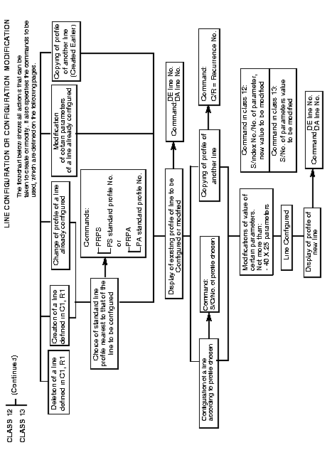
| CLASS 12 CLASS 13 | æ (Continued) |
| C12 - R0 to R35 |
| C13 - R0 to R35 |
| Parameters displayed | ||
|
| |
|
| Only the modified parameters and their new values are displayed in the various recurrences of classes 12 and 13. |
index 0 is reserved for the no of the standard profile chosen
| WARNING: concerning class 12 The characters in the left-hand column on the screen are no longer the parameter nos. but the positioning indices of modified parameters | 0 1 2 3 4 . | --
--,-- --,-- --,-- --,-- |
|
| . 39 COMMAND | --,-- New value of parameter
¿---- No. of modified parameter |
| CLASS 12 CLASS 13 | æ (Continued) |
Meanings and possible value of parameters
Appendix B for X.25, SDLC, VIP, BSC, frame relay and channel B or D (ISDN) parameters.
Appendix C for X.3 parameters.
Appendix D for PSTN parameters.
Appendix E for VIP parameters.
Appendix F for BSC 3270 parameters.
Appendix G for BSC 2780/3780 parameters.
Appendix H for transparent BSC parameters.
Appendix I for parameters related to PLL management in a D channel.
Appendix J for the parameters related to LMI management.
Profile of an asynchronous terminal
| C14 - R0 | X.3 customer profile | ||
Parameters displayed | Meanings of parameters | Possible values | |
| 0 1 2 . . . 22 --------- COMMAND | 80 | The X.3 profile defined in this recurrence has the standard profile No. 80. (See AppendixA). | See Appendix C. |
This class is used to compose the Videotex welcome page.
The messages configured in R1 are displayed with the attributes configured in R0.
| C15 - R0 | Message attributes | ||
Parameters displayed | Meanings of parameters | Possible values | |
0 --,--,--,--,--,--,--,--,--,-- | Each parameter corresponds to one block.
The blocks displayed are made up of up to 10 terms. These terms describe the attributes used for the composition of the welcome messages configured in R1. | --,--,--,--,--,--,--,--,--,-- __________________ | | | 10 hexadecimal terms | |
| 1st term: Delimiter of beginning of positioning attributes Value = 1 F (US) 2nd term: Cursor positioning attribute, for line No. value = use column 4 to 7 of the table of ASCII characters (40 hexa = line 0) Example: Line No. in position 24 = 58 hexa | ||
| C15 - R0 | (Continued) | ||
Parameters displayed | Meanings of parameters | Meaning of terms and possible values | |
|
| ||
| C15 - R0 | (Continued) | ||
Parameters displayed | Meanings of parameters | Meaning of terms and possible values | |
|
| ||
| C15 - R1 | Contents of message | ||
Parameters displayed | Meanings of parameters | Meaning of terms and possible values | |
| 0 . . . . 99 COMMAND | ------------
------------ | Each parameter corresponds to the parameter having the same number in R0 and is used to compose a welcome message. The texts configured in the blocks of this recurrence are displayed with the attributes described in R0. | Message consisting of up to 12 alphanumeric characters per parameter. Example: Cisco-VDX-01 In accordance with STUPAV, after this message, the service message "service code" is sent. |
This class is used to compose the PAD welcome page.
The messages configured in R1 are displayed with the attributes configured in R0.
| C16 - R0 | Message attributes | ||
Parameters displayed | Meanings of parameters | Meaning of terms and possible values | |
0 --,--,--,--,--,--,--,--,--,-- | Each parameter corresponds to one block. The blocks displayed are made up of up to 10 terms. These terms describe the attributes used in composing the welcome messages configured in R1. | --,--,--,--,--,--,--,--,--,-- _________________ | | | 10 hexadecimal terms | |
| When the terminal connected to the PAD permits, the attributes have the same meaning as those of a Prestel type Videotex terminal (see C15R0) | ||
| C16 - R1 | Message contents | ||
Parameters displayed | Meanings of parameters | Possible values | |
0 ------------ | Each parameter corresponds to the parameter having the same No. in R0 and is used to compose a welcome message. The texts configured in the blocks of this recurrence are displayed with the attributes described in R0. | Message made up of 12 alphanumeric characters. Example: Paris-PAD-02 | |
| C17 - R0 | Table of PVCs/DLCI | ||
Parameters displayed | Meanings of parameters | Possible values | |
0 --,-,----,---- | Configuration of Permanent Virtual Circuits or the DLCI number or LLC (virtual router). | --,-,----,---- | | | | | | | | | | | | | | | Remote logical channel | | | No. (0 to 250) or local | | | address (AB or ABSA) | |
| | | | or emergency LLC No | | | (FBE and FRR (case of | | | redundant) remote LMX | | | Local logical channel No (0 to | | 250) or local DLCI (0 to 1023) l | | or local LLC number (1 to 254) | | | 0 = Calling | 1 = Called | 2 = Mixed | 3 = Datagram (only for FRR) | 4 = Called party without calling | party address check Auto-call position No. (1 to 200) defined in C8-R0 to R5. | ||
| Note: |
| |
| C18 - R0 to R35 | CUG for the lines 0 to 35 | ||
Parameters displayed | Meanings of parameters | Possible values | |
0 --,--,-- |
|
--,--,-- | | | | |
|
|
| | |
| C18 - R36 | CUG for management functions | ||
Parameters displayed | Meanings of parameters | Possible values | |
| 0 . . . 95 COMMAND | --,--,--
--,--,--, | Control of access to management functions is enhanced by up to 4 specific configurable CUGs configurable for each function. The first one is used for transfering of data in such functions as the configuration; for the configurator the first CUG offers a supplementary control level with the key | --,--,-- | | | | | | |
| (C0, R0): encoding is the same as other recurrences in the class. | Processing 00 = incoming and outgoing call 02 = outgoing call | |
| PARAMETERS | FUNCTIONS | |
|---|---|---|
| 0 to 3 | Observation | |
| 4 to 7 | Statistics | |
| 8 to 11 | Outstanding events | |
| 12 to 15 | Alarms | |
| 16 to 19 | Traffic generator | |
| 20 to 23 | File transfer | |
| 24 to 27 | Maintenance | |
| 28 to 31 | Configuration | |
| 32 to 35 | MMI | |
| 36 to 39 | Billing | |
| 40 to 43 | Extended statistics | |
| 44 to 47 | Reserved | |
| 48 to 51 | Reserved | |
| 52 to 55 | MAP | |
| 56 to 59 | | | |
| 60 to 63 | | | |
| 64 to 67 | | | |
| 68 to 71 | | | |
| 72 to 75 | | | Reserved |
| 76 to 79 | | | |
| 80 to 83 | | | |
| 84 to 87 | | | |
| 88 to 91 | | | |
| 92 to 95 | | |
| C18 - R37 to R49 | CUG for the virtuals functions | ||
Parameters displayed | Meanings of parameters | Possible values | |
| 0 . . 27 COMMAND | --,--,--
--,--,-- | See C18R0 to R35. | See C18R0 to R35. |
| C19 - R0 | SDLC clusters, VIP controllers, BSC 3270 and BSC 2780/3780 | |||
Parameters displayed | Meanings of parameters | Possible values | ||
| 0 . . 199 COMMAND | --,---
--,--,--,-- | Position of clusters or controllers | SDLC --,--- | | | Cluster address (0 to 254) | | |
| Position of automatic call (1 to 200) defined in (C8, R0 and R5) | |||
| VIP --,--,--,-- | | | | | | | Position 1st station(C13) | | | | | Number of VIP stations (1 to 232) | | if = 0 polling station | or station | |||
| C19 - R0 | (Continued) | |||
Parameters displayed | Meanings of parameters | Possible values | ||
| BSC 3270 | |||
| | | | C | |||
| A, B and C are the terminal addresses to be used in BSC 3780; in BSC 2780, these bytes are not used.
| |||
| C20 - R0 | Modem initialization table | ||
Parameters displayed | Meanings of parameters | Possible values | |
| 0 1 2 COMMAND | ----...----
----...---- ----...---- | Each parameter stands for a string of characters allowing to initialize the modem. | A string contains up to 50 alphanumeric characters. |
| C21 - R0 | 1st XID frame | ||
Parameters displayed | Meanings of parameters | Possible values | |
| 0 . . 9 COMMAND | ----...----
----...---- | A XID frame can contains from 0 to 256 bytes; 10 parameters of 26 bytes each are use to describe it. | Each parameter contains up to 26 hexadecimal characters. Ex: 82FFCC0441424344CD00. Note: The frame format is described on page 3.6.8. |
| C21 - R2 | 3rd XID frame |
| C21 - R2 | 3rd XID frame |
| C21 - R3 | 4th XID frame |
| C22 - R0 | X.121 address table | ||
Parameters displayed | Meanings of parameters | Possible values | |
| 0 1 2 3 . . . 249 COMMAND | 1234567-------- 891011==1415---- 19>-----------
;
--------------- | Each parameter corresponds to an X.25 address. It is matched with the equivalent parameter number of recurrences 1 and 2. These recurrences define respectively the ISDN or PSTN address or the behavior on outgoing and incoming calls. In the case of an incoming call, this parameter is not significant. | The X.121 address is coded in quartets on 8 bytes. When this address begins with the character ";" any X.121 address is accepted in the case of ISDN. The E.164 or PSTN address and the associated behavior are defined in recurrences 1 and 2 as in the normal case. When a "=" character is encountered in the address, the digit is ignored and the analysis is continued. |
| The ">" character is used as an extraction marker. The digits to the left of this marker constitute a prefix to be ignored. Example: 1234>41280000 After extraction, the address becomes: 41280000. Each parameter contains up to 16 characters. | ||
| C22 - R1 | PNTN/ISDN E.164 address table | ||
Parameters displayed | Meanings of parameters | Possible values | |
| 0 1 2 3 4 . . . 249 COMMAND | 12345678
4629 45361521 112233== 46879656:1234 | In the case of conversion without extraction, the parameter corresponds to an E.164 or PSTN number. With address extraction, the parameter corresponds to the beginning of the E.164 or PSTN number. The rest of the E.164 or PSTN number is extracted from the X.121 address of the call request packet as of the prefix defined in recurrence 0. This parameter is matched with the equivalent parameters of recurrences 0 and 2 which | The E.164 or PSTN address is coded in quartet on 14 bytes (number + sub-address). Case of PSTN: Description of coding. The telephone number is composed of digits and of an indicator whose description is as follows: 0 to 9 : digits : : wait for dial tone ; : pause of 2 seconds |
| represent respectively the X.121 address and the behavior. With address extraction, the subaddress is not managed. | < : pulse dialling = : tone dialling > : indication to hang up for 1/2 second ? : end of number Delimiter Example: = 16;47026320? | |
| C22 - R1 | (Continued) | ||
Parameters displayed | Meanings of parameters | Possible values | |
| Case of ISDN on outgoing call:
|
| |
| C22 - R1 | (Continued) | ||
Parameters displayed | Meanings of parameters | Possible values | |
| Case of ISDN: checking of E.164 address on incoming call. Each parameter corresponds to an ISDN address and is matched with the equivalent parameter number of recurrence 2. This defines the behavior and the recurrence number in C30 defining the X.25 parameters to be adopted on an incoming call.
|
When this address begins with the ";" character, the behavior defined in recurrence 2 is applied to all calls, regardless of the caller, even if it is not furnished by the network. | |
| **before**When the caller is located in the Paris region, the ISDN address of the caller, received by the called party in the establishment message, is preceded by 1. It is thus essential that the ISDN address of the caller, defined in C22 R1, also be preceded by 1.@@before@@ | Warning **after**When the caller is located in the Paris region, the ISDN address of the caller, received by the called party in the establishment message, is preceded by 1. It is thus essential that the ISDN address of the caller, defined in C22 R1, also be preceded by 1.@@after@@ |
CLASS 22 - (Continued)
| C22 - R2 | Additional information on outgoing and incoming call | ||
Parameters displayed | Meanings of parameters | Possible values | |
| 0 . . 249 COMMAND | -,-,-,-,-,-,-,-
-,-,-,-,-,-,-,- | These parameters define the behavior to be adopted on outgoing and incoming calls. The first 3 bytes must be defines (fixed part). The next 5 bytes (variable part allowing configuration of up to 5 actions amount 8 (optional). | 8 bytes defined as follows: byte 0: 7 6 5 4 3 2 1 0 bit |__|___|____|___|___|___|___|__| _____ | | | | | | | | | | | |
| When these options are not defined, a default behavior is adopted:
|
| | | Type of protocol 7 6 5 4 3 2 1 0 bit | |
A5 - Number of attempts associated with the ISDN number (multiple backup)
|
| ||
| C22 - R2 | (Continued) | ||
Parameters displayed | Meanings of parameters | Possible values | |
|
|
byte 2: | |
|
|
byte 3: | |
| C22 - R2 | (Continued) | ||
Param. displayed | Meanings of parameters | Possible values | |
| Action 2: Direction assigned to ISDN number (towards an MLP bundle) (not used for PSTN) This action is used only in the case where two different MLP bundles are associated with the same DNIC ZO and the same ISDN number. The only means of differentiating them is to associate a different direction with these bundles. 20 = direction 0 (default value) 21 = direction 1 2F = direction 15 Action 3: Exchange of XID frames 30 = Sending of XID, frame No 0 31 = Sending of XID, frame No 1 32 = Sending of XID, frame No 2 33 = Sending of XID, frame No 3 38 = Reception of XID mandatory | ||
| C22 - R2 | (Continued) | ||
Parameters displayed | Meanings of parameters | Possible values | |
| Action 4: Extraction of E.164 address from X.25 address of call request packet 41 = 1 digit of the PSTN/ISDN number. 4F = 15 digits of the PSTN/ISDN number. The PSTN/ISDN number is deduced from elimination and then addition of a prefix. By default, action 4 is absent fi conversion use. Action 5: Number of attempts associated with the ISDN number (multiple backup). (not used for PSTN) 51 = 1 5F = 15 | ||
| C22 - R2 | (Continued) | ||
Parameters displayed | Meanings of parameters | Possible values | |
| Action 6: Number of attempts associated with the last number of the ISDN number list (multiple backup) (not used for PSTN) 61 = 1 . . . . . . . 7F = 15 Highest priority | ||
| C20 - R0 | Flow control | ||
Parameters displayed | Meanings of parameters | Possible values | |
| 0
1 | 4,4,3,3,2,2,2,2,2,2, -,-,-,-,-,-,-,-,-,- -,-,-,-,-,-,-,-,-,- | Each parameter has 10 packet windows sizes (values from 1 to 7) corresponding to the 10 possible packet lengths (16, 32, 64, 128, 256, 512, 1024, 2048, 4096, 8192). | P0 = default value P1 = Reserved P2 = Reserved |
| C24 - R0 | Internal subscriber of management functions |
| This recurrence is defined the same way a recurrence in C12 is defined and it uses the X.25 profile 06. The meaning of the parameters are given in AppendixB.
|
| Parameters displayed | ||
|
| |
|
| Only the modified parameters and their new values are displayed in the various recurrences of class 24. |
Index 0 is reserved for profile No. 06.
| WARNING: concerning class 24. | 0 1 2 | 06 --,-- --,-- |
| The characters in the left-hand column on the screen are no longer the parameter nos. but the positioning indices of modified parameters | 34 4 . | --,-- |
| . 39 --,-- New parameter value COMMAND |---- No. of the modified parameter |
Attention ! Barring exceptions, the parameters can not be modified.
C24 - R1 = ESV-N4 securized lines with profile number 45.
C24 - R2 = IR securized lines with profile number 46.
C24 - R3 = X.29 rerouting with profile number 81.
C24 - R4 = Compression with profile number 96.
C24 - R5 = DLM with profile number 110.
C24 - R6 to R8 = Virtual router (FastPAD modules) with profile number 112.
C24 - R9 = Reserved
Any modification of this class leads to a total reset (ITO) of the equipment.
| C25 - R0 to R8 | MLP line bundles | ||
| Parameters displayed | Meanings of parameters | Possible values | Example
|
| 0 - 1 - 2 - 3 -- 4 -- 5 -- 6 -- 7 -- 8 -- 9 -- 10 -- 11 -- 12 - 13 - 14 - 15 -- 16 -- | Bundle function number defining the main line (number of main line) Reserved Number of lines per bundle Number of main line Number of second line Number of third line Number of fourth line Number of fifth line Number of sixth line Number of seventh line Number of eighth line Number of ninth line Reserved Reserved Reserved MW Tx/Rx window size MX guard window size | 0 to 35 0 to 9 00 to 35 00 to 35 00 to 35 00 to 35 00 to 35 00 to 35 00 to 35 00 to 35 00 to 35 01 to 32 01to 32 |
32 32 20 |
| 17 ----
18 --- 19 --- 20 --- 21 - 22 --- 23 --- COMMAND | MT1 frame loss time-out
Supervision time-out, reset MPL, MT3 Line out of service to MT4 Maximum number of frames sent on a link Reserved Transmission of restart upon reception of MLP reset TNS3 level 3 supervision time-out | 01 to 255 steps = 1 S
00 to 255 steps = 1 S 001 to 255 - 0 = NO 1 1 = YES 000 to 255 (step = 10 S) (if 000 = supervision not active) | 10
40 3
1
10 10 |
| Remarks: |
|
| |
| ||
|
Important: | MLP parameters must be symmetrical at the two ends of the bundle. A complete reset must be given after a modification on the parameters of the class 25. | |
| C26 - R0 | |||
Parameters displayed | Meanings of parameters | Possible values | |
0 --------- | Only the following combinations are managed:
|
A Reserved | |
| Ex : | Parameter 0 | : | DACE90402180BFF701000 | X.25 field: E called party address A calling party address |
| . DA | : | Destruction of calling address | F Facility B, C, D reserved | |
| . CE90402180 | : | Change the called address to 90402180. | ||
| . BF701000 | : | Addition of reliability 701000 at output of switch. |
This class contains the recurrences (R0 to R15) defining the dynamic connection parameters of the packets in B or D channels or frame relay.
This class also contains the static connection, parameters of the PLLs of the network FR (FRTE). The lines making reference to it are defined in class 32, recurrence 1.
These recurrences are defined the same way as a recurrence in class 12.
| Parameters displayed | ||
| There is no need to display all the X.25 parameters on the screen because:
|
| |
|
| Only the modified parameters and their new values are displayed in the various recurrences of class 30. |
ÈIndex 0 is reserved for the profile number
| WARNING: concerning class 30 The characters in the left-hand column on the screen are no longer the parameter nos. but the positioning indices of modified parameters | 0 -- 1 --,-- 2 . . | |
| 3 . . 4 . | ||
| . 39 --,-- New parameter value COMMAND ¿---- No. of the modified parameter |
The meaning of the values of parameter values are given in AppendixB.
| C31 - R0 | Reserved | ||
| C31 - R1 | Reserved | ||
| C31 - R2 | Reserved | ||
| C31 - R3 | Reserved | ||
| C31 - R4 | Reserved | ||
| C31 - R5 | Reserved | ||
| C31 - R6 | Reserved |
| C31 - R7 | Definition of IP addresses on WAN interface | ||
Parameters displayed | Meanings of parameters | Possible values | |
| 0 . . 5 COMMAND | --,--,--,--
--,--,--,-- | Primary IP addresses on WAN side. | 4 bytes in decimal separated by commas. |
| C31 - R8 | Definition of IP addresses on LAN interface | ||
Parameters displayed | Meanings of parameters | Possible values | |
| 0 1 19 COMMAND | --,--,--,--
--,--,--,-- --,--,--,-- | Primary IP address of router on LAN side. Secondary IP address of router on LAN side. | 4 bytes in decimal separated by commas. 4 bytes in decimal separated by commas. |
| C31 - R9 | Reserved | ||
| C31 - R10 | Reserved | ||
| C31 - R11 | Definition of LAN interfaces | ||
Parameters displayed | Meanings of parameters | Possible values | |
| 0 . . 19 COMMAND | --,--,--,--,--,-- | Definition of primary and secondary interfaces on LAN side, of associated LLC Helpers and type of encapsulation. | --,--,--,-- reserved | | | | reserved | | | | reserved | | | | | | | | reserved | | | | |
| | | | reserved | Minimum and maximum IP address row in C31 R12 and R13 (1 to 200) | ||
| C31 - R12 | Table of minimum IP addresses | ||
Parameters displayed | Meanings of parameters | Possible values | |
| 0 . . 199 COMMAND | --,--,--,-- | IP address defining the minimum of an address range. | 4 bytes in decimal separated by commas. |
| C31 - R13 | Table of maximum IP addresses | ||
Parameters displayed | Meanings of parameters | Possible values | |
| 0 . . 199 COMMAND | --,--,--,-- | IP address defining the maximum of an address range. | 4 bytes in decimal separated by commas. |
| C31 - R14 | IP routing table (to WAN) | ||
Parameters displayed | Meanings of parameters | Possible values | |
| 0 . . 199 COMMAND | --,---,--
--,--,--, -- | Definition of IP address ranges and of associated LLC. | --,---,-- | | | | | Reserved | LLC No. (1 to 254) Row No. of minimum and maximum IP addresses defined in C31 R12 and |
| R13 (1 to 200) | ||
| C31 - R15 | Default routing | ||
Parameters displayed | Meanings of parameters | Possible values | |
| 0. . 3 COMMAND | --- | Definition of default route. | --- Number of LLCs in decimal (1 to 254). |
| C31 - R16 | Reserved | ||
| C31 - R17 | Reserved | ||
| C31 - R18 | Reserved | ||
| C31 - R19 | List of community names for SNMP | ||
Parameters displayed | Meanings of parameters | Possible values | |
| 0 1 2 COMMAND | ------... | Community name for reading only of MIB. Community name for reading/writing of MIB. Community name for traps. | String of characters up to 14 bytes. |
| C31 - R20 | Table of IP address of SNMP managers | ||
Parameters displayed | Meanings of parameters | Possible values | |
| 0 . . . 5 COMMAND | --,--,--,--,-- | IP address of managers authorized to use the SNMP agent and associated community name. | --,--,--,--,-- _______ | | Row No. of community name | defined in C31 R19 (0 to 1) | IP address on 4 bytes in decimal separated by commas. |
| C31 - R21 | Table of broadcast IP addresses for SNMP traps | ||
Parameters displayed | Meanings of parameters | Possible values | |
| 0 1 2 COMMAND | --,--,--,-- | IP address for traps. | 4 bytes in decimal separated by commas. |
| C31 - R22 | Value of ports | ||
Parameters displayed | Meanings of parameters | Possible values | |
| 0 1 2 COMMAND | ---- | UDP port No. for SNMP. UDP port No. for TRAP-PDU SNMPs. Port No. for RIP. | 2 bytes in hexadecimal. |
| C31 - R23 | Reserved | ||
| C32 - R0 | a = line,, type, priority (optional) | ||
Parameters displayed | Meanings of parameters | Possible values | |
| 0 . . 199 COMMAND | --,,----,-
--,,---- | PLL. | ---,,----,- | | | Priority of couple | | 1 = High priority (ex: VOICEPAC) | | 0 = Low priority | | DLCI number (0 to 1023) |
| | | | | | Line number (00 to 35) | ||
| C32 - R1 | b = line, PLL, rec C30 | ||
Parameters displayed | Meanings of parameters | Possible values | |
| 0 . . 199 COMMAND | --,,----,--
--,-,---- | PLL. | ---,-,----,-- | | | | Recurrence of profile defined in C30 for a | | | virtual line (160 to 239) | | DLCI Number | | (0 to 1023) |
| | Type of PLL | 0 = DLCI Connection type (1 virtual line in recurrence > 1) | 1 = DLCI "Final" type | 2 = DLCI "TRANSIT" type Line number (00 to 35) Virtual line (160, 239) and (65, 124) | ||
|
|