|
|

Use the StrataView Plus Connection Manager to create and maintain end-to-end Frame Relay and ATM connections. Frame relay connections include dial-up and dial backup connections when the network is enhanced with the Intelligent Network Server (INS) Dial-Up Frame Relay application. Parameters that you define at the Connection Manager Window are validated and sent to either the INS server or Connection Manager server.
You can open up to four Connection Manager windows at a SV+ desktop.
The Connection Manager Window presents updated status information as dependent on the Connection Mode selected at the Main Window. Connection Modes are either Normal Mode or Dial-Up Mode. Normal Mode presents standard Frame Relay and ATM Connections (PVCs), and Dial-up Mode presents INS Dial-up and Dial-Backup connections (PVCs).
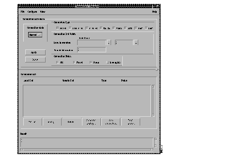
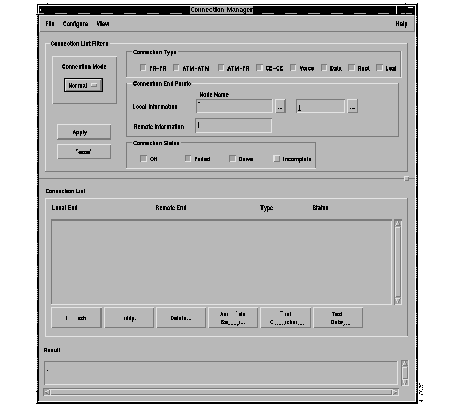
Use this window to configure end-to-end frame relay, ATM, CE - CE, Voice and Data connections. See Figure 7-1 and Figure 7-2 for the Connection Manager Main Window and its Menu.
This release of StrataView Plus allows you to add. delete, modify, or view voice and data connections.
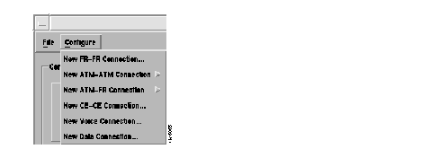
The pulldown menu in Figure 7-2 shows the connections you can configure from the Connection Manager Main window. The Voice and Data connections are different from Frame Relay and ATM connections in that certain parameters for voice/data are associated with channel rather than connection.
| Connection List Filters | This portion of the window is used to specify the filters that should be used when building the Connection list. Once all the desired fields have been filled, press the 'Apply' button to update the connection list. |
| Connection Mode | This button toggles to either Network mode or INS ANI mode.
Normal mode displays standard Frame Relay and ATM Connections (PVCs). INS ANI mode displays the INS Dial-Up and Dial-Backup Identifications (ANIs). |
| Connection Type | A radio box allowing the user to specify the type of connection to be configured. Connection Type may be FR - FR, ATM - ATM, ATM - FR, or CE - CE. |
| Connection Status | A radio box allowing the user to specify 1 or more types of connection status that should be used to filter the list of connections. Connection Status may be OK, Failed, Incomplete, and Down. |
| Local Information | Node name and port number of the local end-point. Any or all these fields may be specified. The button with the "..." label next to the shelf text entry field opens a scroll list of node names and a corresponding shelf name if the node name entered corresponds to a BPX. |
| Remote Node Name | A text edit window for the user to specify that only connections to this remote node from the local node will be displayed. If no remote node is designated, connections from the local node to all other nodes are to be displayed. |
| Connection List | A scrolling text window displaying all the connections which match the filter criteria. The user may select one or more entries from this list for modification or delete. Each entry in the list has the following format: |
| Local end-point | <nodename>.<interfaceshelfname>.<slot>.<port>.<DLCI> or <nodename>.<interfaceshelfname>.<slot>.<port>.<vpi>.<vci>
If the end-point is a frame relay end-point the first format is used, if it is an ATM end-point the second format is used. If shelf is not applicable the shelf field will be omitted. For an ATM end-point the second format is used. If shelf is not applicable the shelf field will be omitted. |
| Remote end-point | <remotenode>.
If the end-point is a frame relay end-point the first format is used, if it is an ATM end-point the second format is used. If shelf is not applicable the shelf field will be omitted. |
| Connection type | Connection Type may be FR - FR, ATM - ATM, ATM - FR, CE - CE, Voice, or Data. |
| Connection status | Any incomplete connection segments in feeder shelves and BNI-BNI connection segment in BPXs display the unknown termination points as "Unknown" and an "Incomplete" status. The remote end may report BPX node, slot, port, vpi, and vci. |
| Apply button | This button updates the entries in connection list according to the criteria set in the filter field. |
| Refresh button | Indicates that the connection database has changed by changing its background color to red. This button updates the connection list with the new information. |
| Associate Backup button | The Associate Backup dialog box has two basic functions, "Add Association," and "Delete Association."
The "Associated to PVC?" column indicates whether or not the Dial-Backup PVC is already associated to a Normal PVC. If the Selected Normal PVC is already associated with a Dial-Backup PVC, then the Display fields at the top of the window are updated to indicate which ANI and which Dial-Backup PVC is already associated to this Normal PVC. If the Normal PVC is already associated, select "Delete" to remove the association. The user can then select a Dial-Backup PVC and "Add" to add a new association. The Add association is performed by selecting the Add Association... button. The selected Normal PVC is then associated with the selected Dial-Backup PVC. Only Dial-Backup PVCs that have NO association to a PVC can be selected for association. The Dial Backup ANI will never have more than five Dial-Backup PVCs. |
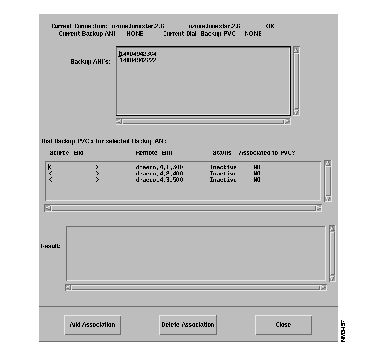
The ANI field is a 20 character numeric field. It is selected from a listbox that is popped up when the "..." button is depressed. When an ANI is selected, all of the connections defined on the INS server for the selected ANI are displayed.
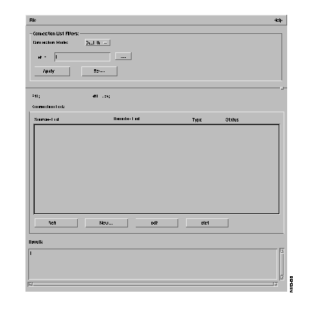
The Main Window connection list display is changed in "Dial-Up" mode, with a connection Status of Active or Inactive in the connection(s) listbox field. Active INS connections cannot be modified. Only connections that are Inactive can be further modified via the main window Modify button or deleted with the Delete button.
To add a new Dial-Up connection to an ANI, select the New button to begin addition of a new connection.
Use this window to set parameters for a new dial-up connection.
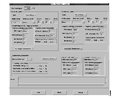
| Local and Remote End-Point | A region to enter local and remote end-point parameters: |
| End PointType | Disabled for FR-FR connections. |
| Port Type | Option Menu for specifying port type of end points to be displayed in port help list connection window. |
| Node Name | A text field to enter node name. The default node name is the local node name specified in the connection filter in the main connection window. |
| Interface Shelf | A text field to enter the interface shelf name. The shelf field will be disabled if the node name refers to an IPX node. |
| Help Button | The button with the label "..." next to the shelf text entry field will pop-up a dialog box to help the user select node name and the corresponding interface shelf name. |
| Port Number | A text field to enter slot number and port number ranges from 1 to the maximum slot number in the shelf. This field does not have any default values. Format: <slot>.<port>. |
| DLCI Number | A text field to enter the DLCI number. Value range is 1-1024. There is no default value for this field. |
| Parameters | These are all the end-point parameters. The parameters will change based on end-point type. All the parameters will be shown with default values. Typically the user will set both end-point's parameters to the same values. |
Ingress Policing Parameters | |
| CIR | A text field to enter the CIR (in kbps) of the end-point. Value range is 0-2048. |
| CMAX | A text field to enter the CMAX (in number of bytes) of the end-point. Value range is 1-255. |
| Bc (Committed Burst Size) | A text field to enter the committed burst size (in bytes) of the end-point. Value range is 1-65535. |
| Be (Excess Burst Size) | A text edit window to enter the excess burst size (in bytes) of the end-point. Value range is 0-65535. |
| Ingress Queue Threshold | |
| Virtual Circuit Queue Depth | A text edit window to enter the VC queue size (in bytes) for the end-point. Value range is 1-65535. Defaults to 65535. |
| ECN Threshold | A text edit window for ECN threshold (specified as% of Virtual Circuit Queue Depth) for the end-point. Value range is 0-100%. |
| Egress Queue Parameters | |
| Priority | A radio box allowing the user to set High or Low as the value. The default is Low. |
| Connection Parameters | This region is used to enter the connection parameters for both local and destination end-points. |
| Use Foresight | A toggle button to enable or disable ForeSight. The default is Foresight disabled. |
| Class of Service | A text field for specifying the re-routing priority of the connection, ranges from 0 to 15. This defaults to 0. |
| Preferred Route | This button that will open the Configure Preferred Route Window, used to specify the preferred route path. Only routes for intra-domain connections may be specified (the network does not support preferred routes of inter-domain connections). |
| Routing Restrictions | This form is used to specify the types of trunks that should be avoided when the connection is routed. |
| Use trunks using ZCS | A radio box is used to specify whether ZCS trunks should be used. Defaults to No. |
| Avoid trunk type | A radio box is used to specify whether satellite links should be used. Defaults to No.
A radio box is used to specify whether terrestrial links should be used. Defaults to No. |
| Originating and Terminating Remote and Remote Terminating and Originating | These 2 forms are used to specify parameters that affect the connection in the direction of the local-end to the remote-end (Local->Remote) and remote-end to local-end (Remote->Local) respectively. |
| Utilization | A text field to set the channel utilization (in percentage). Value range is 1-100. Defaults to 100. |
| Rate control Parameters | |
| MIR | A text field to enter the CIR (in kbps) of the end-point. Value range is 0-2048. Defaults to 9.6. |
| PIR | A text field to enter the PIR (in kbps) of the end-point. Value range is 0-2048. Defaults to the port speed of the connection. |
| QIR | A text edit window to enter the QIR (in kbps) of the end-point. Value range is 0-2048. Defaults to 9.6. |
| Result field | A scrollable read-only window to display the error message or result of the operation. The detailed content of this field will be determined during design. |
Use this menu to set new parameters for existing connectivity configurations. See Figure 7-6 for an example of the Modify Connection window.
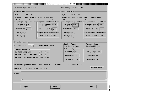
| Local and Remote End Point | A region to enter local and remote end-point parameters. End point type and End point identification information is not editable.
The Type, Node name, Interface Shelf, Slot #, Port #, DLCI fields are not editable. |
| Parameters | These are all the end-point parameters. These parameters can be modified. |
| Ingress policing parameters | |
| CIR | A text field to enter the CIR (in kbps) of the end-point. Value range is 0-2048. |
| CMAX | A text field to enter the CMAX (in number of bytes) of the end-point. Value range is 1-255. |
| Bc (Committed Burst Size) | A text field to enter the committed burst size (in bytes) of the end-point. Value range is 1-65535. |
| Be (Excess Burst Size) | A text edit window to enter the excess burst size (in bytes) of the end-point. Value range is 0-65535. |
| Be (Excess Burst Size) | A text edit window to enter the excess burst size (in bytes) of the end-point. Value range is 0-65535. |
| Virtual Circuit Queue Depth | A text edit window to enter the VC queue size (in bytes) for the end-point. Value range is 1-65535. |
| ECN Threshold | A text edit window for ECN threshold (specified as% of Virtual Circuit Queue Depth) for the end-point. Value range is 0-100%. |
| Egress Queue Parameters | |
| Priority | A radio box allowing the user to set High or Low as the value. The default is Low. |
| Connection Parameters | |
| Use Foresight | A toggle button to enable or disable ForeSight. There is no default for modifying. |
| Class of Service | A text field for specifying the re-routing priority of the connection, ranges from 0-15. |
| Route Master | A node name of the node that is responsible for routing this connection. This field is not editable. |
| Routing Restrictions | This form is used to specify the types of trunks that should be avoided when the connection is routed. |
| Use trunks using ZCS | A radio box is used to specify whether ZCS trunks should be used. |
| Avoid trunk types option menu | A radio box is used to specify whether satellite links should be used. |
| Avoid trunk types option menu | A radio box is used to specify whether terrestrial links should be used. |
| Originating -Terminating Terminating - Originating | These 2 forms are used to specify parameters that affect the connection in the direction of the local-end to the remote-end (Local->Remote) and remote-end to local-end (Remote->Local) respectively. |
| Utilization | A text field to set the channel utilization (in percentage). Value range is 1-100. |
| Rate Control Parameters | |
| MIR | A text field to enter the CIR (in kbps) of the end-point. Value range is 0-2048. |
| PIR | A text field to enter the PIR (in kbps) of the end-point. Value range is 0-2048. |
| QIR | A text edit window to enter the QIR (in kbps) of the end-point. Value range is 0-2048. |
| Connection segments | This field displays all the connection segments that make up the entire connection.
The format is: <local-endpt><intermediate-endpoint1>, |
| Current Route | This field displays the current route of the connection.
The format is: <node name> [<out trunk> -- <in trunk> <node name>] The portion within the square brackets may be repeated up to |
| Preferred Route | This button opens the Configure Preferred Route Window, used to specify the preferred route path. Only routes for intra-domain connections may be specified (the network does not support preferred routes of inter-domain connections). |
| Result Field | A scrollable read-only window to display the error message or result of the operation. The detailed content of this field will be determined during design. |
| Apply Button | This button modifies the end-points and connection parameters, the result of the operation will be displayed in the result window. Once the user requests a modify, all buttons on this window will be disabled and this window will stay open till the action is completed. |
| Reset Button | The button to clear all the values currently shown on the screen and restore the original values for the connection. |
| Cancel Button | Use this button to close the window. |
In this section, we will focus on how to add a connection. Figure 7-7 shows an example of the Configure Menu window.
Specific screens listed in Figure 7-7 show the following types of connections:
Connection type--This section allows the user to specify the connection type further. For example for ATM-ATM, and ATM-FR connections the service type specification will be displayed here.
Originating/Terminating end-point definition--This section provides for the specification of the originating/terminating end-point. A user can choose an end-point type of ATM or Frame Relay. Different fields will be displayed for defining the end-point depending on the end-point type and the end-point card type. The end-point card type is automatically determined by the GUI.
An end-point is defined by its end-point type and its node, [shelf], slot, [line], port, and [channel] information. Examples of specific terminating end-point definitions are as follows:
The prompt for end-point definition has changed from the prompt used in Release 8.1. Instead of prompting for Node name, Interface Shelf, Slot, Line, and Port, you will be prompted for Node Name where Node Name will be in the form <Node Name.Shelf Name> and Port number will be in the form <slot#.logical port#>. A logical port number is defined to be unique across a given slot.
Physical port was used in release 8.1 while logical port is used in release 8.2.
As an example; in order to represent node bpx01, shelf axis01, slot 5, line 1, physical port 1, logical port 10, dlci 100, for Release 8.1 you would enter:
bpx01 axis01 5 1 1 100
but in Release 8.2 you would enter:
bpx01.axis01 5.10 100.
Based on the end-point type appropriate Originating/Terminating end-point parameters are displayed in the region just below this one.
Use the New Voice Connection Window, shown in Figure 7-8 to configure or modify voice connections.
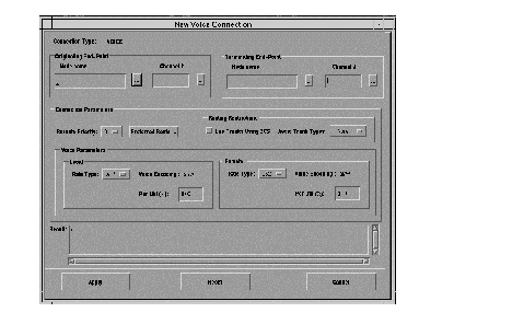
The New Voice Connection Window layout is consistent with the existing connection windows. The remote and local end points contain Node Name and Channel Number Fields. No DLCI or VPI/VCI fields are required for voice connections.
The Channel Number field for voice connections has the following syntax:
slot.[line.]chanl
where slot: (3..32),
line: (1..2),
chan: If the CDP is configured as CAS, the valid range is 1-15, and 17-31 (channel 16 is reserved).
For CCS: the valid range is 1-31.
Note that this field is configurable on a per-line basis, after the line was been activated (via upln) and before the first connection is added.
The Node Help, and Tab key validation remain same as in the previous release of StrataView Plus. The SlotPort Help dialog display slots on which you can create voice connections. You need to manually enter the channel number after clicking on Apply.
The Connection Manager supports voice connection across a tiered IGX/BPX network. The connection types supported are given in the following table.
| Connection Types | Local End | Remote End |
|---|---|---|
| 1 Segment Connection | CVM, UVM | CVM, UVM |
| 2 Segment Connection* | CVM, UVM | CVM, UVM |
| 3 Segment Connection | CVM, UVM | CVM, UVM |
The Voice Parameters are given in the following table:
| Field Name | Values | Constraint |
|---|---|---|
| Rate Type | a32, a24, a16, a16z, a32d, c32, c24, c16, c16z, | Rate Type is mandatory for creation and cannot be modified
daxcon must use rate types: p, t, or v. l16, l16v, l8, l8v only enabled for UVM card on which LDCELP was supported Only 16 LDCELP connections (ratetype: l*) are supported on one UVM (initial release) l8, l8v rate types exist in SNMP MIB. But since they will not be supported in release 9.0, remove them from GUI |
| Voice Encoding | alaw, ulaw | |
| Percent Utilization | 0 - 100 (%) |
The following features have been added to help StrataView Plus users:
This functionality will not be available from service agent side. When the service agent for voice/data connections is implemented, you will be able to add asymmetric connections described in the preceding bulleted list.
You can configure or modify data connections from the New Data Connection Window shown in Figure 7-9.
.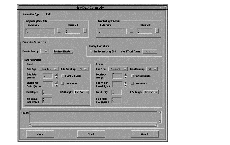
The New Data Connection Window layout is consistent with the existing connection windows. The remote and local end points contain Node Name and Channel Number Fields. No DLCI or VPI/VCI fields are required for data connection.
The Channel Number field for data connections has the following syntax:
	slot.[line.]chanl
	where slot: (3..32), line: (1..2),chan
	chan: If the CDP is configured as CAS, the valid range is 1-15, and 17-31.
		For CCS: 1-31.
		Note that this field is configurable on a per-line basis, after
		the line was been activated (via upln) and before the first connection
		is added.
The Node Help, and Tab key validation remain same as in the previous release of StrataView Plus. The SlotPort Help dialog display slots on which you can create data connections. You need to manually enter the channel number after clicking on Apply.
The Connection Manager supports data connection across the tiered IGX/BPX network. The connection types supported are given in the following table.
| Connection Types | Local End | Remote End |
|---|---|---|
| 1 Segment Connection | CVM, HDM, LDM | CVM, HDM, LDM |
| 3 Segment Connection | CVM, HDM, LDM | CVM, HDM, LDM |
For a standard rate data connection, enter the data rate in the text or use the arrow keys. Each click increases/decreases the data rate to the next supported value. Press without releasing the arrow keys enters the fast increase/decrease mode.
The Sample Per Packet field is enabled only for standard rate. It specifies the number of samples per packet for connection rate that support partially-filled packets. The allowable value depends on the data rate you select.
	two-bytes:  12, 18, 24, 32, 36
	four-bytes: 24, 32, 36, 48, 64, 72
	five-bytes: 32, 36, 48, 64, 72
	ten-bytes:  48, 64, 72, 80, 96, 120, 128, 144
The Fast EIA Enable is enabled only for standard rate connections.
| Field Name | *Values | Constraint |
|---|---|---|
| Data Rate | Standard Rates
1.2, 1.2f, 1.8, 1.8f, 2.4, 2.4f, 3.2, 3.2f, 3.6, 3.6f, 4.8, 4.8f, 6.4, 6.4f, 7.2, 7.2f, 8, 8f, 9.6, 9.6f, 12.8, 12.8f, 14.4, 14.4f, 16, 16f, 19.2, 19.2f, 24, 24f, 28.8, 28.8f, 32, 32f, 38.4, 38.4f, 48, 48f, 56, 56f, 57.6, 57.6f, 64, 64f, 72, 72f, 76.8, 76.8f, 84, 84f, 96, 96f, 112, 112f, 115.2, 115.2f, 128, 128f, 144, 144f, 168, 168f, 192, 192f, 224, 224f, 230.4, 230.4f, 256, 256f, 288, 288f, 336, 336f, 384, 384f, 448, 448f, 512, 512f, 672, 768, 772, 896, 1024, 1344, 12, 12f, 16.8, 16.8f, 1152, 1.2f/2, 1.8f/2, 2.4/4, 2.4f/5, 2.4f/2, 2.4f/5, 2.4f/2, 3.2/4, 3.2f/5, 3.2f/2, 3.2f/5, 3.2f/2, 3.6/4, 3.6f/5, 3.6f/2, 3.6f/5, 3.6f/2, 4.8/10, 4.8/4, 4.8/10, 4.8/4, 4.8f/5, 6.4/10, 6.4/4, 6.4/10, 6.4/4, 6.4f/5, 7.2/10, 7.2/4, 7.2/10, 7.2/4, 7.2f/5, 8/10, 9.6/10, 12.8/10, 14.4/10, 12/10 Super-Rate:1x56, 2x56, 3x56, 4x56, 5x56, 6x56, 7x56, 8x56, 1x64, 2x64, 3x64, 4x64, 5x64, 6x 64, 7x64, 8x64 Transparent Subrate:2.4t, 4.8t, 9.6t, 56t, 2.4/4t, 4.8/10t, 4.8/4t, 9.6/10t | SNMP uses INTEGER type for data rate setting, but it accepts only supported rates. |
| Data Encoding | 7/8, 8/8, 8/8I, 7/8E | 8/8, 8/8I, 7/8E not applicable for ZCS trunks |
| Fast EIA Enable | enable/disable | only for data rate =< 5120 (100 bps) |
| Sample Per Packet | 2, 4, 5, 10, MAX | only for partially filled connections |
| DFM Enable | enable/disable | only for data rate =< 1920 (100 bps)
Cannot be enabled if embedded EIA is configured on the port |
| DFM Length | 1, 7, 8, 16 | valid only when DFM is enabled. Cannot be configured if embedded EIA is configured |
| EIA Update Rate | 0 - 20 | |
| Percent Utilization | 0 - 100 (%) | not meaningful for CVM and UVM cards |
An ATM-ATM connection is one in which both originating and terminating end-point types are ATM.
Several different service types (for example, CBR.1, VBR.x, ABR.FS, and UBR.x) are supported for ATM connections. Based on the service type selected, the end-point and connection parameters are changed. Parameters that are common across the different screens are only described on the first screen that they are shown in.
Both ASI and AUSM end-points have the same parameters, the range and default values are different for the 2 end-point types. For each service type the range and default values for all relevant parameters are shown.
Figure 7-10 shows the parameters required to add a CBR.1 ATM connection. In this case, from the users perspective both ASI and AUSM end-points have the same parameters. The ranges and default values that are valid for the two end-point types are listed in this section. Additional end-point and connection parameters required by the network elements (BPX, AXIS) and not shown on the screen will be set automatically by Connection Manager Daemon.
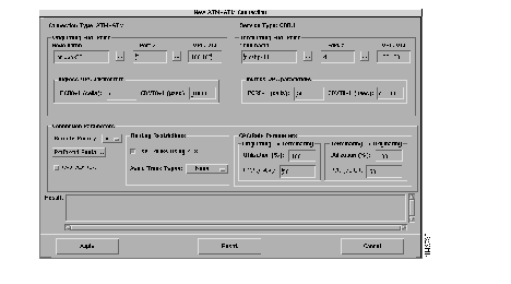
ATM-ATM CBR.1 connection configuration parameters are shown below:
Connection Classification

End-point and connection parameters for CBR.1 connections are given in Tables 7-3 and 7-4 respectively.
| Parameter (units) | ASI | AUSM | ||
|---|---|---|---|---|
| Range | Default | Range | Default | |
| PCR0+1 (cells) | 10-port rate
(96k/80k/353208) | 10 | 10-port rate
(3622/4528/4830) | port rate
|
| CDVT0+1 | 1-250,000 | 10,000 | 1-250,000 | 10,000
|
| Utilization (%) | 1-100 | 100 | 1-100 | 100 |
| Parameter (units) | ASI | AUSM | ||
|---|---|---|---|---|
| Range | Default | Range | Default | |
| MCR (cells) not editable | 10 -port rate | PCR0+1 | 10-port rate | PCR0+1 |
| %Utilization | 1-100 | 100 | 1-100 | 100 |
Figure 7-11 shows the parameters required to add a VBR.1 ATM connection. This section will only discuss the parameters that are different from the ones already discussed for ATM CBR.1 connections. The ranges and default values that are valid for ASI and AUSM end-point types are listed in Table 7-7.
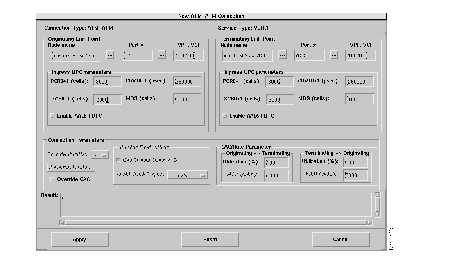
End-point parameters (Originating and Terminating) for VBR.1 connections
Connection Parameters
ATM-ATM Connection windows for VBR.2 and VBR.3 are shown is Figure7-12 and 7-13, respectively.
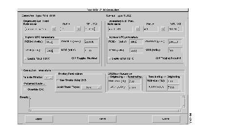
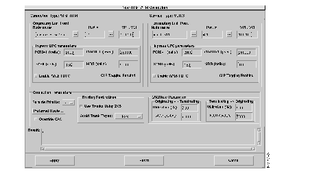
Parameters for VBR connections are given in the following tables. See Table 7-5 for ASI and AUSM end-point parameters and Table 7-6 for connection parameters.
| Parameter (units) | ASI | AUSM | ||
|---|---|---|---|---|
| Range | Default | Range | Default | |
| PCR0+1 (cells) | 10-port rate | 10 | 10-port rate | port rate |
| CDVT0+1 | 1-250,000 | 10,000 | 1-250,000 | 10,000 |
| SCR0+1 (cells) | 10-port rate | 10 | 10-port rate | port rate |
| MBS (cells) | 1-24,000 | 1000 | 1-5,000 | 1,000 |
Utilization (%) | 1-100 | 100 | 1-100 | MIN(1.2* SCR/PCR01, 100) |
| MCR (not editable) | same as PCR0+1 | PCR0+1 | same as PCR0+1 | PCR0+1 |
Figure 7-14 shows the parameters required to add an ABR.FS ATM connection. This section will only discuss the parameters that are different from the ones already discussed for CBR and VBR connections.
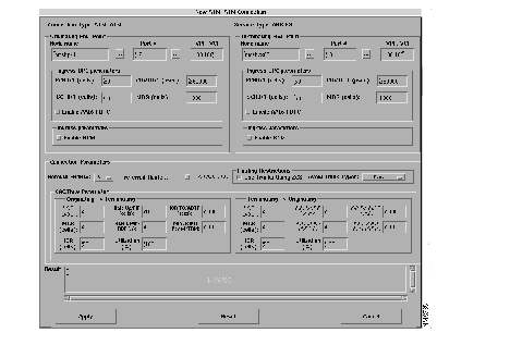
End-point parameters (Originating and Terminating) for ABR.FS connections:
ASI and AUSM end-point parameters for ABR.FS connections are given in Table 7-7.
| Parameter (units) | ASI | AUSM | ||
|---|---|---|---|---|
| Range | Default | Range | Default | |
| PCR0+1 (cells) | 10-port rate | 10 | 10-port rate | port rate |
| CDVT0+1 | 1-250,000 | 10,000 | 1-250,000 | 10,000 |
| SCR0+1 (cells) | 10-port rate | 10 | 10 | port rate |
| MBS | 1-24,000 | 1,000 | 1-5,000 | 10,000 |
| PCR (not settable) | same as PCR0+1 | PCR0+1 | same as PCR0+1 | PCR0+1 |
| MCR (cells) | 0-port rate | 0 | 0-port rate | 0 |
FRSM end-points support both service interworking and network interworking options. In the case of FRP end-points only network interworking is possible.
The option menu for the end-point type in both the originating and terminating end-point sections allow values of Frame Relay and ATM. The only restriction is that if ATM is specified in one end-point then Frame Relay must be specified in the other.
An originating FRSM end-point and a terminating AUSM end-point are given for an ABR.FS connection. The AUSM ABR.FS parameters are the same as those discussed earlier. The FRSM end-point supports the following additional parameters:
Connection parameters for ABR.FS connections are given in Table 7-8.
| Parameter (units) | ASI/BNI | AUSM | ||
|---|---|---|---|---|
| Range | Default | Range | Default | |
| Utilization (%) | 1-100 | 100 | 1-100 | 100 |
| PCR (cells) not editable | 10-port rate | PCR0+1 | 11-8000 | PCR0+1 |
| MCR (cells) | 0-240,000
| 0 | 0-port rate | 0 |
| ICR (cells) | 0-240,000 | 1 | 0-port rate | 1 |
| Rate Up (%) | 1-100 | 2 | NA | NA |
| Rate Down (%) | 1-100 | 87 | NA | NA |
| Rate Fast Down (%) | 1-100 | 50 | NA | NA |
| ICR TimeOut (secs) | 1-255 | 10 | NA | NA |
| Min Adjust Period (cells) | 20-250 | 40 | NA | NA |
Figure 7-15 shows an example of the ABR.1 Connection window. Included in this section are tables giving ABR.1 end-point and connection parameters.
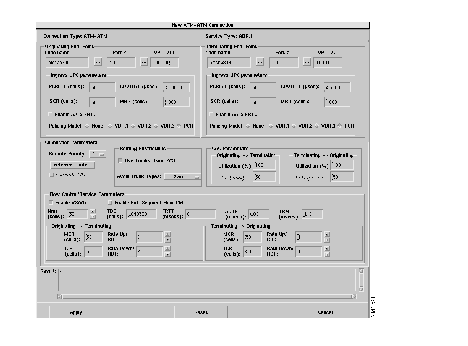
The ASI, BXM, and AUSM end-point parameters for ABR.1 connections are given in the following tables.
| Parameter (units) | Range | Default | Range | Default |
|---|---|---|---|---|
PCR0+1 (cells) | 10-port rate |
|
10-port rate | port rate |
| CDVT0+1 (microseconds) | 0-5,000,000 | 250,000 | 1-250,000 | 1000
|
| SCR (cells) | 10-port rate | 50 | N/A | N/A |
| MBS (cells) | 1-24,000 | 1000 | N/A | N/A |
| Enable AAL5 FBTC | N/A | disabled | N/A | disabled |
| Policing Model | N/A | PCR | N/A | N/A |
| ASI/BXM | AUSM | |||
|---|---|---|---|---|
| Parameter (units) | Range | Default | Range | Default |
Policing Model 1-100 | 100 | 1-100 | 100 | |
| PCR (cells) | (Not editable; always set the same as PCR+1) | |||
| Enable VS/VD | N/A | disabled | N/A | N/A |
| Enable Ext. Segment |
| |||
| Flow Ctrl | N/A | disabled | N/A | N/A |
| Nrm (cells) | 2-256 | 32 | N/A | N/A |
| TBE (cells) | 0-1048320 | 1048320 | N/A | N/A |
| FRTT (msecs) | 0-16700 | 0 | N/A | N/A |
| ADTF (msecs) | 62-8000 | 1000 | N/A | N/A |
| TRM (msecs) | 1-100 | 100 | N/A | N/A |
| MCR (cells) | 0-port rate | 50 | 0-port rate | port rate |
| ICR (cells) | 0-port rate | 50 | N/A | N/A |
| Rate Up/RIF | 1-1/32768 | 1 | N/A | N/A |
| Rate Down/RDF | 1-1/32768 | 1 | N/A | N/A |
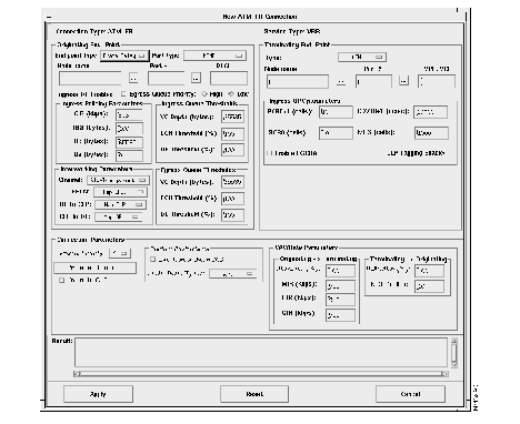
An ATM-FR connection is a connection that has an ATM end-point and a Frame Relay end-point. Only VCC connections are supported for ATM-FR connections. Valid service types for this type of connection are VBR and ABR.FS. Parameters for this connection are shown as per end-points.
This section discusses the parameters that are different from those already discussed in earlier sections on CBR.1, VBR.x, and ABR.FS connections.
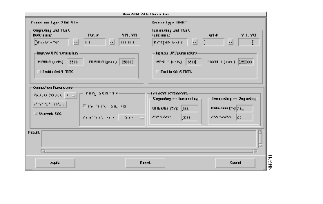
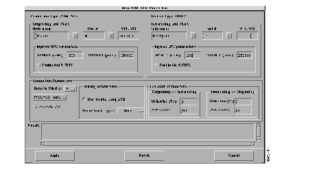
There are no new end-point parameters (originating and terminating) introduced for UBR.x The two parameters are PCR0+1 and CDVT0+1, and are identical to the ones in the CBR.1 connection.
There are no new connection parameters introduced for UBR.x. The two parameters are utilization and PCR, and are identical to the ones in the CBR.1 connection.
ASI, BXM, and AUSM end-point parameters for UBR.x connections are given in the following tables.
| ASI/BXM | AUSM | |||
|---|---|---|---|---|
| Parameter (units) | Range | Default | Range | Default |
| PCR0+1 (cells) | 10-port rate | 50 | 10-port rate | port rate |
| CDVT0+1 (microseconds) | 0-5,000,000 | 10,000 | 1-250,000 | 10,000 |
| ASI/BXM | AUSM | |||
|---|---|---|---|---|
| Parameter (units) | Range | Default | Range | Default |
| Utilization (%) | 1-100 | 1 | 1-100 | 100 |
PCR (cells) Not editable; always set the same as PCR0+1 | ||||
A CE connection is one in which both originating and terminating end-point types are CESM. Figure 7-19 shows the parameters required to add a CE connection.
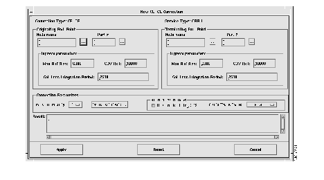
End-point parameters (Originating and Terminating) for CE Connections
Connection parameters for CE-CE connections are given in Table 7-13.
| Parameter (units) | ASI | AUSM | ||
|---|---|---|---|---|
| Range | Default | Range | Default | |
| Max Buf Size | 0.6*CDV RxT--65535
0.78*CDV RxT-65535 | 6000/
7000 | ||
| CDV RxT | 1000 - 65535 | 10,000 | ||
| Cell Loss Integration Period | 1000 - 65535 | 2500 | ||
| Utilization (%) | 1-100 | Min (1.2*SCR/PCR, 100 | 1-100 | Min (1.2*SCR/PCR01,100 |
|
|