|
|

This appendix provides details on the IPX peripheral equipment, including printers and modems. The appendix includes the following sections:
A StrataView Plus workstation is required for managing a network containing IPX, IGX, and BPX nodes and associated equipment. Refer to the StrataView Plus Operations Guide and StrataView Plus Installation document for setup instructions and specifications for the StrataView Plus NMS which is required to provide network alarm, control, and statistics monitoring.
A terminal (pc or workstation, including a StrataView Plus workstation) can be connected to the CONTROL port of an IPX for temporary or local control. This can be especially useful during installtion, initial power-up, and configuration. Refer to Table B-1 for configuration data on the IPX CONTROL port. .
| Parameter | Requirement |
|---|---|
| IPX Port Used: | CONTROL terminal port on the SCC card is used to interface to a local terminal. |
| Code: | Standard 7 or 8-bit ASCII; 1 or 2 stop-bits; even, odd or no parity. |
| Interface: | RS-232 DCE. |
| Data Rate: | All standard asynchronous data rates from 300 to 19200 bps, independently software-selectable. |
| Supported Terminals: | VT-100, or equivalent, recommended. |
| Cable Required: | Straight-through RS-232 cable. |
The maintenance printer that is currently shipped with the IPX is the Okidata Model 184. This printer may be connected to any node. Refer to Table B-2 and Table B-3 for interface requirements.
| IPX Port Used: | AUX port on the SCC card is used to interface with the maintenance printer. |
|---|---|
| Code: | Standard 8-bit ASCII; 8 data bits, 1 stop-bit, odd parity. |
| Interface: | RS-232 DCE. |
| Data Rate: | 9600 baud. |
| Supported Printers: | Okidata 184. |
| Cable Required: | Straight-through RS-232 cable. |
DIP Switch A is an 8-section DIP switch located on the printer's main circuit board. Access to the configuration switches is made by sliding back the switch cover at the top, rear of the printer case. Set Switch A as indicated in Table B-3.
| Switch A | Setting | Description |
|---|---|---|
| 1 | Off | ASCII with non-slashed zero. |
| 2 | Off | |
| 3 | Off | |
| 4 | Off | 11-inch paper. |
| 5 | On | |
| 6 | Off | No Auto Line Feed. |
| 7 | On | 8- bit data. |
| 8 | Off | Enables front panel. |
The High Speed Serial Interface DIP Switch consists of two DIP switches, SW1 and SW2, located on a serial-board that is attached to the printer's main board. Set switches 1 and 2 as indicated in Table B-4 and Table B-5.
| Switch 1 | Setting | Description |
|---|---|---|
| 1 | On | Odd parity. |
| 2 | On | No parity. |
| 3 | On | 8 data bits. |
| 4 | On | Ready/busy protocol. |
| 5 | On | Test select circuit. |
| 6 | On | Print mode. |
| 7 | On | Busy line selection. |
| 8 | On | DTR pin 2 enabled. |
| Switch 2 | Setting | Description |
|---|---|---|
| 1 | Off | Transmission speed = 9600 baud. |
| 2 | On | |
| 3 | On | |
| 4 | On | DSR active. |
| 5 | On | Buffer = 32 bytes. |
| 6 | On | Timing = 200 ms. |
| 7 | On | Space after power on. |
| 8 | Don't care | Not used. |
Customer service uses modems for diagnosing and correcting customer problems with installed IPX systems. The modem that is currently recommended for use withthe IPX is the Codex model V.34R.
A dial-in connection to an IPX from customer service via a modem uses the CONTROL port of the IPX.A dial-out connection from an IPX via a modem to customer service uses the AUX port of the IPX. Refer to Table B-6 for interface requirements.
| Parameter | Requirement |
|---|---|
| IPX Port Used: | CONTROL port on SCC card is used for auto-answer modem. AUX PORT on SCC card is used for auto-dial modem. |
| Code: | Standard 8-bit ASCII, 1 stop-bit, no parity. |
| Interface: | RS-232 DCE. |
| Cable: | Null modem cable: CONTROL or AUX port to modem (DCE to DCE) |
| Phone Lines: | Dedicated, dial-up business telephone line for Customer Service-to-IPX modem and auto-dial-to-Customer Service modem. |
| Data Rate: | All standard asynchronous data rates from 300 to 19200 bps, independently software-selectable. |
| Supported Modems: | Motorola V.34R 28.8 modem. |
The following is a setup procedure that allows customer service to dial in to the customer's IPX to provide support and troubleshooting:
Step 1 Using the cnfterm command, set the IPX CONTROL port speed to 9600 bps.
Step 2 Using the cnftermfunc command, set the terminal type to VT100/StrataView.
Step 3 To program the modem, temporarily attach a terminal to the modem using a straight-through cable (DTE to DCE). The modem EIA port will automatically match the 9600 bps setting of the terminal.
Step 4 Enter the commands listed in Table B-7 to set up the modem for proper operation.
Step 5 Disconnect the terminal and the straight-through cable from the IPX CONTROL port.
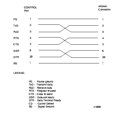
Step 6 Connect the modem to the IPX CONTROL port using a null modem cable Figure B-1. A null modem cable is used, as the connection is essentially a DCE to DCE rather than a DTE to DCE.
Step 7 Ask Customer Service to assist in testing the operation of the modem setup.
| Step | Command | Function |
|---|---|---|
| 1. | AT&F&W | Reset to factory default and save. |
| 2. | ATSØ=1 | Enables Auto-Answer Mode (answer on first ring). |
| 3. | ATL1 | Modem speaker at low volume. |
| 4. | AT*SM3 | Enables automatic MNP error correction. |
| 5 | AT*DC0 | Disables data compression. |
| 6. | AT*FL0 | Disables XON/XOFF flow control. |
| 7. | AT&S1 | Sets DSR to "normal". |
| 8. | ATEØ | Disables local character echo. |
| 9. | ATQ1 | Disables result codes. (Modem will appear "dead.) |
| 10. | AT&W | Saves current configuration settings in non-volatile memory. |
The following is a setup procedure for the customer's IPX to dial up customer service.
Step 1 Using the cnfterm command, set the IPX Auxiliary port (AUX PORT) speed to 9600 bps and enable XON/XOFF flow control.
Step 2 Using the cnftermfunc command, select option 7, "Autodial Modem" and enter the customer service-designated Network ID, and the customer service modem phone number.
Step 3 Attach a 9600 bps terminal to the modem using a straight-through cable. The modem EIA port will automatically match the 9600 bps setting of the terminal.
Step 4 Enter the commands listed in either Table B-8 (V.34R modem without talk/data pushbutton) or Table B-9 (V.34R modem with talk/data pushbutton), to set up the modem for proper operation.
Step 5 Disconnect the terminal and the straight-through cable from the IPX CONTROL port.
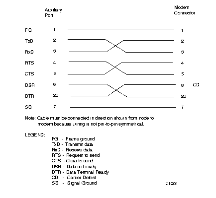
Step 6 Connect the modem to the IPX AUX port using a null modem cable Figure B-2.
Step 7 Ask customer service to assist in testing the operation of the modem setup.
| Step | Command | Function |
|---|---|---|
These configuration commands are for a V.34R modem that does not have a talk/data pushbutton. | ||
| 1. | AT&F | Initializes factory defaults. |
| 2. | ATL1 | Modem speaker at minimum volume. |
| 3. | AT*SM3 | Enables automatic MNP error correction. |
| 4 | AT*DC0 | Disables data compression. |
| 5. | AT*SC1 | Enables DTE speed conversion. |
| 6. | AT*FL1 | Enables XON/XOFF flow control. |
| 7. | AT*SI1 | Enables 5-minute inactivity disconnect. |
| 8. | AT&C1 | DCD controlled by modem. |
| 9. | AT&D2 | Modem disconnects when IPX toggles DTR. |
| 10. | AT&V | Verify entries. |
| 11. | AT&W | Saves current settings to non-volatile memory.
|
| Step | Command | Function |
|---|---|---|
These configuration commands are for a V.34R modem that has a talk/data pushbutton. | ||
| 1. | AT&F | Initializes factory defaults. |
| 2. | ATL1 | Modem speaker at minimum volume. |
| 3 | AT\N3 | To enable MNP error correction. |
| 4 | AT%C | To disable data compression. |
| 5 | AT\J | Enables DTE speed conversion. |
| 6 | AT\Q1 | Enables_______flow control. |
| 7 | AT\T3 | Enables 3-minute inactivity timer. |
| 8. | AT&C1 | DCD controlled by modem. |
| 9. | AT&D2 | Modem disconnects when IPX toggles DTR. |
| 10. | AT&V | Verify entries. (shows current configuration). |
| 11. | AT&W | Saves current settings to non-volatile memory. |
|
|