|
|
This chapter provides information on various cables and transceivers. The information is organized into the following sections:
If a product number in this chapter ends with an equal sign (=), the item can be ordered only as a spare. If a product number does not end with an equal sign, the item can be ordered as a spare or as a configurable part of a system order. For example, a serial cable ordered as part of an original order uses part number CAB-232FC. The same cable ordered as a spare uses part number CAB232FC=.
bug-doc@cisco.com.
Table 326 lists Ethernet transceivers and applicable systems.
Table 326 : Ethernet Transceivers
| Description | Systems | Product Number |
|---|---|---|
| Thin Ethernet BNC transceiver with
9.8-foot (3meter) attachment unit interface (AUI) cable |
AGS+
ASM-CS Cisco 7000 family Cisco 4000 series Cisco 3000 series Cisco 2500 series Access Server series |
COM-13B= |
| Thick Ethernet, N-series transceiver with
9.8foot (3-meter) AUI cable |
AGS+
ASM-CS Cisco 7000 family Cisco 4000 series Cisco 3000 series Cisco 2500 series Access Server series |
COM-13N= |
| Thick Ethernet piercing-tap transceiver with 9.8-foot (3-meter) cable | AGS+
ASM-CS Cisco 7000 family Cisco 4000 series Cisco 3000 series Cisco 2500 series Access Server series |
COM-13V= |
| Shielded transceiver with 49-foot (15-meter) cable | AGS+
ASM-CS Cisco 7000 family Cisco 4000 series Cisco 3000 series Cisco 2500 series Access Server series |
COM-14A= |
| Unshielded transceiver with a 16.4-foot (5-meter) cable | AGS+
ASM-CS Cisco 7000 family Cisco 4000 series Cisco 3000 series Cisco 2500 series Access Server series |
COM-14B= |
| Two 50-ohm thick Ethernet cable terminators | AGS+
ASM-CS Cisco 7000 family Cisco 4000 series Cisco 3000 series Cisco 2500 series Access Server series |
COM-14TA= |
| Two 50-ohm thin Ethernet cable terminators | AGS+
ASM-CS Cisco 7000 family Cisco 4000 series Cisco 3000 series Cisco 2500 series Access Server series |
COM-14TB= |
Following is a list of Cisco-approved cable vendors:
LoDan West, Inc.
1050 Commercial Street
San Carlos, California 94070
Tel: 415 592-4600
Fax: 415 592-4054
Volex, Inc.
646 Caribbean Drive
Sunnyvale, CA 94089
Tel: 408-541-4600
Fax: 408-541-4640
Storm Products Co.
1400 Memorex Drive
Santa Clara, California 95050
Tel: 408 565-9800
Fax: 408 565-9820
The JPM Company
Route 15 North
Lewisburg, PA 17837
Tel: 717-524-8200
Fax: 717-524-8181
or their Pacific Coast representative
Camino Sales
Tel: 415-968-4099
Fax: 415-968-2645
Table 327 lists T1/DSUs and applicable systems.
| Description | System | Product Number |
|---|---|---|
| T1 Switched Multimegabit Data Service (SMDS) DSU, 110 VAC
Vendor: Kentrox |
AGS+
ASM-CS Cisco 7000 family Cisco 4000 series Cisco 3000 series Cisco 2500 series Access Server series |
COM-SNI1= |
| T1/DSU
Vendor: Digital Link |
AGS+
ASM-CS Cisco 7000 family Cisco 4000 series Cisco 3000 series Cisco 2500 series Access Server series |
COM-T1= |
Table 328 lists DSU/channel service unit (CSU) cables.
| Description | Cable | DSU/CSU |
|---|---|---|
| EIA/TIA-449 female to EIA-530 male cable, 3 ft. (1 m) | CAB-SDS1= | COM-SNI1=
COM-T1= |
| DA-15 female to pigtail cable, 24.6 ft. (7.5 m) | CAB-SDS6= | COM-SNI1=
COM-T1= |
| DA-15 female to RJ-48 male cable, 24.6 ft. (7.5 m) | CAB-SDS0= | COM-SNI1=
COM-T1= |
One of the most complicated parts of setting up a router is the selection of the serial cables to connect the router to the serial devices in your network. There are many different serial cables with seemingly similar features, and finding the correct cable can be a challenge. The information that follows will quickly and easily guide you through the process of selecting the right serial cables for your network.
Selecting the proper serial cable is as easy as knowing the answers to three questions:
With the answers to these questions, and the model of your router, you can read the part number of the cable required from Table 330.
Devices that communicate over a serial interface are divided into two modes: data terminal equipment (DTE) and data communications equipment (DCE). The most important difference between these types of devices is that the DCE device supplies the clock signal that paces the communications on the bus. The documentation that came with the device should indicate whether it is DTE or DCE (some devices have a jumper to select either mode). If you cannot find the information in the documentation, use Table 329 to help you select the proper class.
Table 329 : DTE or DCE Determination
| DTE | DCE | Selectable
DTE or DCE1 |
|
|---|---|---|---|
| Device | Terminals | Modems
CSU/DSU Multiplexers |
Hubs
Routers |
| Gender | Male | Female | Either |
If pins protrude from the base of the connector, the plug is male. If the connector has holes to accept the pins, the receptacle is female. Refer to Figure 157 to identify the connector you need.
A number of different standards define the signaling over a serial cable (including EIA/TIA-232, X.21, V.35, EIA/TIA-449, EIA-530, and EIA613 HSSI). Each standard defines the signals on the cable and specifies the connector at the end of the cable. The documentation for the device being connected should indicate the signaling standard used for that device. If you cannot find the information in the documentation, use the illustrations inside to select the signaling standard required. Select the connector in Figure 157 that will mate with the connector on your device, not the illustration that looks like the connector on the device.
Figure 157 : Serial Cable Connectors---Network Ends
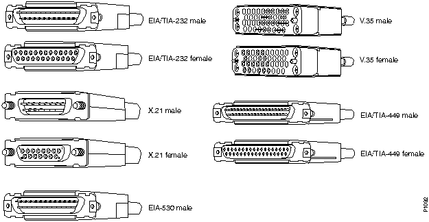
Table 330 : Serial Cable Part Numbers
| Mode | Cable Gender | Signaling | Cisco 7000 Family
Cisco 2500 Series Cisco 4000 NP-4T Access Server Series |
Cisco 4000 NP2T | AGS+ |
|---|---|---|---|---|---|
| DTE | Male | EIA/TIA-232 | CAB-232MT= | CAB-NP232T= | CAB-R23=
CAB-R23NZ= |
| EIA/TIA-449 | CAB-449MT= | CAB-NP449T= | CAB-R44= | ||
| V.35 | CAB-V35MT= | CAB-NPV35TV2= | CAB-VTM= | ||
| X.21 | CAB-X21MT= | CAB-NPX21T= | CAB-IX= | ||
| EIA-530 | CAB-530MT= | CAB-NP530= | -- | ||
| HSSI | CAB-HSI1=1 | -- | CAB-HSI1= | ||
| ASYNC | CAB-OCTAL-ASYNC=2 | -- | -- | ||
| V.35 | -- | -- | CAB-V35MTS=3 | ||
| -- | CAB-PCA-VA=4 | -- | -- | ||
| -- | CAB-PCA-VB=4 | -- | -- | ||
| -- | CAB-PCA-Y=4 | -- | -- | ||
| T1 | CAB-7KCT1DB15=5 | -- | -- | ||
| E1 | CAB-E1-BNC=5 | -- | -- | ||
| E1 | CAB-E1-DB15=5 | -- | -- | ||
| E1 | CAB-E1-PRI=5 | -- | -- | ||
| E1 | CAB-E1-TWINAX=5 | -- | -- | ||
| Female | V.35 | CAB-V35FT=1 | -- | CAB-VTF= | |
| DCE | Male | V.35 | CAB-V35MC= | -- | CAB-VCM= |
| HSSI | CAB-HNUL=1 | -- | CAB-HNUL= | ||
| T1 | CAB-7KCT1NULL=5 | -- | -- | ||
| Female | EIA/TIA-232 | CAB-232FC= | CAB-NP232C= | CAB-R23= | |
| EIA/TIA-449 | CAB-449FC= | CAB-NP449C= | CAB-R44= | ||
| V.35 | CAB-V35FC= | CAB-NPV35CV2= | CAB-VCF= | ||
| X.21 | CAB-X21FC= | CAB-NPX21C= | -- |
To order serial cables and other Cisco products, contact Cisco as described in the chapter "Ordering Products."
This section describes serial cables by product and part number. The illustrations in this section show the Cisco end and the network end of each serial cable. The connector on the left is the Cisco end of the cable. The connector on the right is network end of the cable.
The following illustration shows serial cable CAB-232FC= (part number 72-0794-01), which is used in the following systems: the Cisco 7000 family, Cisco 4000 series (4T), and the Cisco 2500 series. This cable has a male DB-60 connector on the Cisco end and a female DB-25 connector on the network end.
![]()
The following illustration shows serial cable CAB-232MT= (part number 72-0793-01), which is used in the following systems: the Cisco 7000 family, Cisco 4000 series (4T), and the Cisco 2500 series. This cable has a male DB-60 connector on the Cisco end and a male DB-25 connector on the network end.
![]()
The following illustration shows adapter CAB-25AS-MMOD= (part number CAB-25AS-MMOD), which is used in the following systems: the Cisco 2500 series, including the Access Server series (Cisco 2509 through Cisco 2512). This adapter has an RJ-45 connector on one side and a male DB-25 connector on the other side.
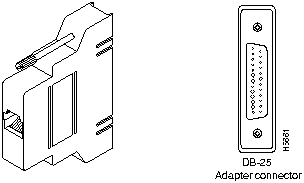
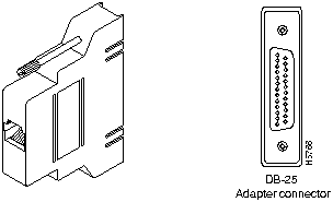
The following illustration shows adapter CAB-25AS-FDTE= (part number CAB-25AS-FDTE), which is used in the Cisco 2500 series, including the Access Server series (Cisco 2509 through Cisco 2512). This adapter has an RJ-45 connector on one side and a female DB-25 connector on the other side.
The following illustration shows serial cable CAB-449FC= (part number 72-0796-01), which is used in the following systems: the Cisco 7000 family, Cisco 4000 series (4T), and the Cisco 2500 series. This cable has a male DB-60 connector on the Cisco end and a female DB-37 connector on the network end.
![]()
The following illustration shows serial cable CAB-449MT= (part number 72-0795-01), which is used in the following systems: the Cisco 7000 family, Cisco 4000 series (4T), and the Cisco 2500 series. This cable has a male DB-60 connector on the Cisco end and a male DB-37 connector on the network end.
![]()
The following illustration shows serial cable CAB-500RJ= (part number 31-0590-01), which is used in the following systems: the Cisco 2500 series and the Cisco CS500. This cable has an RJ-45 connector on both ends.

The following illustration shows serial cable CAB-530MT= (part number 72-0797-01), which is used in the following systems: the Cisco 7000 family, Cisco 4000 series (4T), and the Cisco 2500 series. This cable has a male DB-60 connector on the Cisco end and a male DB-25 connector on the network end.
![]()
The following illustration shows serial cable CAB-7KCT1DB15= (part number 72-0799-00), which is used in the following systems: the Cisco 7500 series, 7000 series, and the Cisco 4000 series. This cable has a male DB-15 connector on the Cisco end and a male DB-15 connector on the network end.
![]()
The following illustration shows serial cable CAB-7KCT1NULL= (part number 72-0800-00), which is used in the following systems: the Cisco 7500 series, 7000 series, and the Cisco 4000 series. This cable has a male DB-15 connector on the Cisco end and a male DB-15 connector on the network end.
![]()
The following illustration shows serial cable CAB-E1-BNC= (part number CAB-E1-BNC), which is used in the Cisco 7500 series, 7000 series, and the Cisco 4000 series systems. This cable has a male DB-15 connector on the Cisco end and two BNC connectors on the network end.

The following illustration shows serial cable CAB-E1-DB15= (part number CAB-E1-DB15), which is used in the Cisco 7500 series, 7000 series, and the Cisco 4000 series systems. This cable has a male DB-15 connector on the Cisco end and a DB-15 connector on the network end.

The following illustration shows serial cable CAB-E1-PRI= (part number CAB-E1-PRI), which is used in the Cisco 7500 series, 7000 series, and the Cisco 4000 series systems. This cable has a male DB-15 connector on the Cisco end and an RJ-45 connector on the network end.

The following illustration shows serial cable CAB-E1-TWINAX= (part number CAB-E1-TWINAX), which is used in the Cisco 7500 series, 7000 series, and the Cisco 4000 series systems. This cable has a male DB-15 connector on the Cisco end and two BNC connectors on the network end.

The following illustration shows serial cable CAB-HNUL= (part number 75-1000-01), which is used in the Cisco 7500 series, 7000 series, and the Cisco AGS+ systems. This cable has a male DB-50 (SCSI) connector on the Cisco end and a male DB-50 (SCSI) connector on the network end.

The following illustration shows serial cable CAB-HSI1= (part number 75-1001-01), which is used in the Cisco 7500 series, 7000 series, and the Cisco AGS+ systems. This cable has a male DB-50 (SCSI) connector on the Cisco end and a male DB-50 (SCSI) connector on the network end.

The following illustration shows serial cable CAB-NP232C= (part number 72-0736-01), which is used in the Cisco 4000 series (2T) systems. This cable has a male DB-60 connector on the Cisco end and a female DB-25 connector on the network end.
![]()
The following illustrations show serial cable CAB-NP232T= (part number 72-0670-01), which is used in the Cisco 4000 series (2T) systems. This cable has a male DB-60 connector on the Cisco end and a male DB-25 connector on the network end.
![]()
The following illustration shows serial cable CAB-NP449C= (part number 72-0738-01), which is used in the Cisco 4000 series (2T) systems. This cable has a male DB-60 connector on the Cisco end and a female DB-37 connector on the network end.
![]()
The following illustration shows serial cable CAB-NP449T= (part number 72-0672-01), which is used in the Cisco 4000 series (2T) systems. This cable has a male DB-60 connector on the Cisco end and a male DB-37 connector on the network end.
![]()
The following illustration shows serial cable CAB-NP530= (part number 72-0732-01), which is used in the Cisco 4000 series (2T) systems. This cable has a male DB-50 connector on the Cisco end and a male DB-25 connector on the network end.
![]()
The following illustration shows serial cable CAB-NPV35CV2= (part number 72-0740-02), which is used in the Cisco 4000 series (2T) systems. This cable has a male DB-50 connector on the Cisco end and a female Winchester connector on the network end.

The following illustration shows serial cable CAB-NPV35TV2= (part number 72-0671-02), which is used in the Cisco 4000 series (2T) systems. This cable has a male DB-50 connector on the Cisco end and a male Winchester connector on the network end.

The following illustration shows serial cable CAB-NPX21C= (part number 72-0737-01), which is used in the Cisco 4000 series (2T) systems. This cable has a male DB-50 connector on the Cisco end and a female DB-15 connector on the network end.
![]()
The following illustration shows serial cable CAB-NPX21T= (part number 72-0683-02), which is used in the Cisco 4000 series (2T) systems. This cable has a male DB-50 connector on the Cisco end and a male DB-15 connector on the network end.

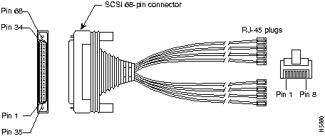
The following illustration shows serial cable CAB-OCTAL-ASYNC= (part number CAB-OCTAL-ASYNC), which is used in the Access Server series (Cisco 2509 through Cisco 2512). This cable has a male DB-68 (SCSI II) connector on the Cisco end and eight RJ-45 connectors on the network end.
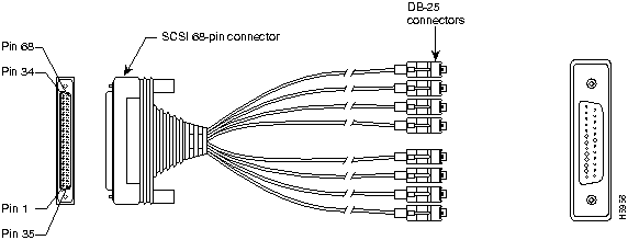
The following illustration shows serial cable CAB-OCTAL-MODEM= (part number CAB-OCTAL-MODEM), which is used in the Access Server series (Cisco 2509 through Cisco 2512). This cable has a male DB-68 (SCSI II) connector on the Cisco end and eight DB-25 connectors on the network end.
The following illustration shows serial cable CAB-PCA-VA= (part number CAB-PCA-VA) and serial cable CAB-PCA-VB= (part number CAB-PCA-VB), which are used in the Cisco 7500 series and 7000 series systems. The CAB-PCA-VA= has a female DB-78 connector on the Cisco end. The CAB-PCA-VB= has a male DB-78 connector on the Cisco end. Both cables have a DB-48 type-A connector on the network end.
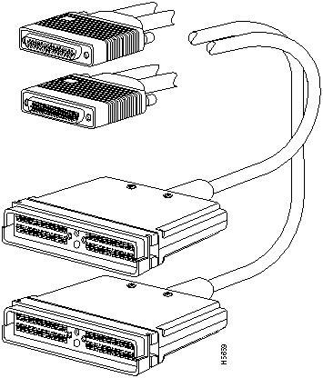
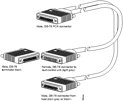
The following illustration shows serial cable CAB-PCA-Y= (part number CAB-PCA-Y), which is used in the Cisco 7500 series and 7000 series systems. The CAB-PCA-Y= is a spare Y cable with female and male DB-78 connectors; this cable ships with the Cisco 7000 series and Cisco 7500 series CIP2.
The following illustration shows serial cable CAB-R23= (part number 74-0173), which is used in the Cisco AGS+ system. This cable has a female DB-25 connector on one end and a male DB-25 connector on the other end. Either end of the CAB-R23 cable can be the Cisco end or the network end, depending on whether the Cisco router is designated as a DCE device or a DTE device. If the router is designated as a DCE device, the female DB-25 connector is the Cisco end. If the router is designated as a DTE device, the male DB-25 connector is the Cisco end.
![]()
The following illustration shows serial cable CAB-R44= (part number 74-0187), which is used in the Cisco AGS+ systems. This cable has a female DB-37 connector on one end and a male DB-37 connector on the other end. Either end of the CAB-R44= cable can be the Cisco end or the network end, depending on whether the Cisco router is designated as a DCE device or a DTE device. If the router is designated as a DCE device, the female DB-37 connector is the Cisco end. If the router is designated as a DTE device, the male DB-37 connector is the Cisco end.

The following illustration shows serial cable CAB-V35FC= (part number 72-0792-01), which is used in the following systems: the Cisco 7000 family, Cisco 4000 series (4T), and the Cisco 2500 series. This cable has a male DB-60 connector on the Cisco end and a female Winchester connector on the network end.

The following illustration shows serial cable CAB-V35FT= (part number 72-0801-01), which is used in the following systems: the Cisco 7500 series, 7000 series, 4000 series (4T), and the Cisco 2500 series. This cable has a male DB-60 connector on the Cisco end and a female Winchester connector on the network end.

The following illustration shows serial cable CAB-V35MC= (part number 72-0802-01), which is used in the following systems: the Cisco 7500 series, 7000 series, 4000 series (4T), and the Cisco 2500 series. This cable has a male DB-60 connector on the Cisco end and a male Winchester connector on the network end.

The following illustration shows serial cable CAB-V35MT= (part number 72-0791-01), which is used in the following systems: all Cisco routers including the Cisco 7000 family, Cisco 4000 series (4T), and the Cisco 2500 series. This cable has a male DB-60 connector on the Cisco end and a male Winchester connector on the network end.

The following illustration shows serial cable CAB-V35MTS= (part number 72-0816-01), which is a generic V.35 DTE translation cable and is used in the following systems: the Cisco AGS+ and the Cisco 1001. This cable has a male shielded Winchester connector on both ends.

The following illustration shows serial cable CAB-VCF= (part number 72-0685), which is used in the Cisco AGS+ system. This cable has a male DB-26 connector on the Cisco end and a female Winchester connector on the network end.

The following illustration shows serial cable CAB-VCM= (part number 72-0681), which is used in the Cisco AGS+ system. This cable has a male DB-26 connector on the Cisco end and a male Winchester connector on the network end.

The following illustration shows serial cable CAB-VTF= (part number 72-0695), which is used in the Cisco AGS+ system. This cable has a male DB-26 connector on the Cisco end and a female Winchester connector on the network end.

The following illustration shows serial cable CAB-VTM= (part number 72-0682), which is used in the Cisco AGS+ system. This cable has a male DB-26 connector on the Cisco end and a male Winchester connector on the network end.

The following illustration shows serial cable CAB-X21FC= (part number 72-0790-01), which is used in the following systems: the Cisco 7000 family, Cisco 4000 series (4T), and the Cisco 2500 series. This cable has a male DB-60 connector on the Cisco end and a female DB-15 connector on the network end.
![]()
The following illustration shows serial cable CAB-X21MT= (part number 72-0789-01), which is used in the following systems: the Cisco 7000 family, Cisco 4000 series (4T), and the Cisco 2500 series. This cable has a male DB-60 connector on the Cisco end and a male DB-15 connector on the network end.
![]()
Cisco products use the following three types of RJ-45 cables:
Cisco does not provide these cables; they are widely available from other sources.
Figure 158 : RJ-45 Cable

To identify RJ-45 cable type, hold the two ends of the cable next to each other so that you can see the colored wires inside the ends, as shown in Figure 159.
Figure 159 : RJ-45 Cable Identification
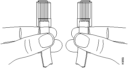
Examine the sequence of colored wires to determine the type of RJ-45 cable, as follows:
The following tables list pinout information for RJ-45 cables.
Table 331 : RJ-45 Straight-Through (Ethernet) Cable Pinouts
| Signal | Pin | Pin | Signal |
|---|---|---|---|
| Tx+ | 1 | 1 | Tx+ |
| Tx-- | 2 | 2 | Tx-- |
| Rx+ | 3 | 3 | Rx+ |
| -- | 4 | 4 | -- |
| -- | 5 | 5 | -- |
| Rx-- | 6 | 6 | Rx-- |
| -- | 7 | 7 | -- |
| -- | 8 | 8 | -- |
Table 332 : RJ-45 Crossover (Ethernet) Cable Pinouts
| Signal | Pin | Pin | Signal |
|---|---|---|---|
| Tx+ | 1 | 3 | Rx+ |
| Tx-- | 2 | 6 | Rx-- |
| Rx+ | 3 | 1 | Tx+ |
| -- | 4 | 4 | -- |
| -- | 5 | 5 | -- |
| Rx-- | 6 | 2 | Tx-- |
| -- | 7 | 7 | -- |
| -- | 8 | 8 | -- |
Table 333 : RJ-45 Rolled (Console) Cable Pinouts
| Signal | Pin | Pin | Signal |
|---|---|---|---|
| -- | 1 | 8 | -- |
| -- | 2 | 7 | -- |
| -- | 3 | 6 | -- |
| -- | 4 | 5 | -- |
| -- | 5 | 4 | -- |
| -- | 6 | 3 | -- |
| -- | 7 | 2 | -- |
| -- | 8 | 1 | -- |
This section describes the cables used with the Cisco LightStream 2020.
For Cisco LightStream 2020 cable product numbers, refer to Table 239 and Table 241 in the "Cisco LightStream 2020" chapter. For detailed cabling information, refer to the chapter "Cables and Connectors" in the LightStream 2020 Site Planning and Cabling Guide.
The X.21 interface cable is used to connect an X.21 fantail to an external X.21 device.

RS-449 Interface Straight-Through Cable
The RS-449 straight-through cable is used to connect an RS-449 fantail to an external RS-449 DCE device.

RS-449 Interface Crossover Cable
The RS-449 interface crossover cable is used to connect two LightStream 2020 switches via their RS-449 fantail interfaces, or to connect an RS-449 fantail to an external RS-449 DTE device.

V.35 Interface Straight-Through Cable
The V.35 interface straight-though cable is used to connect a V.35 fantail to an external V.35 DCE device.

V.35 Interface Crossover Cable
The V.35 interface crossover cable is used to connect two LightStream 2020 switches via their V.35 fantail interfaces, or to connect a V.35 fantail to an external V.35 DTE device.

The 75-ohm coaxial data cable is used for making connections directly to the BNC connectors on the medium-speed access card (MSAC). In addition, this cable can be used as a means of external connection to or from the BNC connector on the T3/E3 fantail.

T3/E3 Fantail and Cable Harness
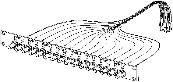
The T3/E3 fantail (dressing panel) contains 16 BNC connectors for external 75-ohm hookup, together with a cable harness that provides the means for direct connection between the back of the T3/E3 fantail and the SMB connectors on a T3AC or an E3AC access card. The T3/E3 fantail and cable harness are available separately.
To interconnect patch panels or T3/E3 fantails to T3AC or E3AC access cards, both 4-port and 8-port coaxial cable harnesses are offered by Cisco Systems.
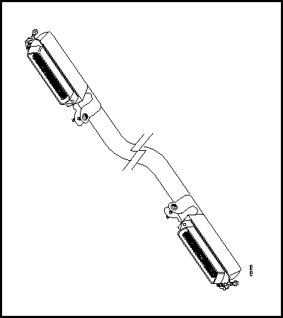
A 50-pin data cable is used as to connect the bulkhead connector on the E1 CEMAC card and the back of the E1 fantail.
Cisco ATM devices support the cable types listed in Table 334 and the cable connectors listed in Table 335. The ATM cables listed in Table 334 are industry standard unless otherwise specified.
Table 335 lists the following connector types:
Figure 157 shows the ATM device mating connectors.
Figure 160 : ATM Connector Types

| Media Type | ATM Forum
Specification |
Cisco 7000
Series1 |
Cisco 4000
Series2 |
LightStream 100
LightStream 1010 |
LightStream 2020 | Catalyst 50003 | ATM SBus Adapter |
|---|---|---|---|---|---|---|---|
| SONET MM | 62.5/125 ∝m4 | 62.5/125 ∝m | 62.5/125 ∝m | 62.5/125 ∝m | 62.5/125 ∝m | 62.5/125 ∝m | 62.5/125 ∝m |
| SONET SM | 8.5/125 ∝m | 8.5/125 ∝m | 8.5/125 ∝m | 8.5/125 ∝m | 8.5/125 ∝m | -- | -- |
| SONET TP | 150-ohm STP5 | -- | -- | 100-ohm UTP6 | -- | 100-ohm UTP | SJ-45 |
| TAXI | 62.5/125 ∝m | 62.5/125 ∝m | -- | 62.5/125 ∝m7 | -- | -- | -- |
| DS3/E3 | 75-ohm coaxial | 75-ohm coaxial | 75-ohm coaxial | 75-ohm coaxial | 75-ohm coaxial | -- | -- |
Table 335 : ATM Cable Connectors
| Media Type | ATM Forum
Specification |
Cisco 7000
Series1 |
Cisco 4000
Series2 |
LightStream 100
LightStream 1010 |
LightStream 2020 | Catalyst 50003 | ATM SBus
Adapter |
|---|---|---|---|---|---|---|---|
| SONET MM | FC or SC4 | SC | SC | SC | SC | SC | SC |
| SONET SM | FC or SC4 | ST | SC | SC | ST | -- | -- |
| SONET TP | DB95 | -- | -- | RJ-45 | -- | RJ-45 | RJ-45 |
| TAXI | FSD | FSD | -- | FSD6 | -- | -- | -- |
| DS3/E3 | RG59-BNC | RG59-BNC7 | RG59-BNC | RG59-BNC | RG59-BNC | -- | -- |
|
|
Copyright 1988-1996 © Cisco Systems Inc.