This publication describes how to upgrade and replace the Flash EPROM memory card in a Cisco 4000 router. Read this entire publication before upgrading your system.
Note This document only applies to the original Cisco 4000 router, later routers in the Cisco 4000 series do not have a Flash EPROM memory card.
The Flash EPROM memory card upgrade kit includes the following components:
- An updated Flash EPROM memory card that supports 8 or 16 MB of Flash memory.
- Updated boot ROMs that provide support for the new Flash EPROM memory card.
 Warning To ensure your safety and the safety of others, be sure the power is OFF and the power cord is unplugged before working on the router.
 Caution To avoid damaging ESD-sensitive components, ensure that you have discharged all static electricity from your body before opening the chassis. Before performing procedures described in this publication, review the following sections: "Safety Recommendations," "Safety with Electricity," and "Tools and Equipment Required."
Follow these guidelines to ensure general safety:
- Keep the chassis area clear and dust-free during and after installation.
- Put the removed chassis cover in a safe place.
- Keep tools away from walk areas where you or others could fall over them.
- Do not wear loose clothing that could get caught in the chassis. Fasten your tie or scarf and roll up your sleeves.
- Wear safety glasses when working under any conditions that might be hazardous to your eyes.
- Do not perform any action that creates a potential hazard to people or makes the equipment unsafe.
 Warning Before working on equipment that is connected to power lines, remove jewelry (including rings, necklaces, and watches). Metal objects will heat up when connected to power and ground and can cause serious burns or can weld to the terminals.
Follow these guidelines when working on equipment powered by electricity:
- Locate the emergency power-off switch in the room in which you are working. Then, if an electrical accident occurs, you can quickly shut the power OFF.
- Before working on the system, turn OFF the power and unplug the power cord.
- Disconnect all power before doing the following:
- Installing or removing a router chassis
- Working near power supplies
- Performing a software upgrade
- Do not work alone if potentially hazardous conditions exist.
- Never assume that power is disconnected from a circuit. Always check.
- Look carefully for possible hazards in your work area, such as moist floors, ungrounded power extension cables, and missing safety grounds.
- If an electrical accident occurs, proceed as follows:
- Use caution; do not become a victim yourself.
- Turn OFF power to the system.
- If possible, send another person to get medical aid. Otherwise, determine the condition of the victim and then call for help.
- Determine if the person needs rescue breathing or external cardiac compressions; then take appropriate action.
Electrostatic discharge (ESD) can damage equipment and impair electrical circuitry. It occurs when electronic printed circuit cards are improperly handled and can result in complete or intermittent failures. Always follow ESD prevention procedures when removing and replacing cards. Ensure that the router chassis is electrically connected to earth ground. Wear an ESD-preventive wrist strap, ensuring that it makes good skin contact. Connect the clip to an unpainted chassis frame surface to safely channel unwanted ESD voltages to ground. To properly guard against ESD damage and shocks, the wrist strap and cord must operate effectively. If no wrist strap is available, ground yourself by touching the metal part of the chassis.
 Caution For safety, periodically check the resistance value of the antistatic strap, which should be within the range of 1 through 10 megohm (Mohms).
You need the following tools and equipment to replace the Flash EPROM memory card in the Cisco 4000.
- ESD cord and wrist strap
- Screwdrivers, Number 1 and Number 2 Phillips
- ROM extraction tool or flat-bladed screwdriver
To access the internal components of the router, you must remove the component tray.
 Warning Hazardous voltages may exist in or near the power supply, so use extreme caution when working near the power supply. Before starting any of these procedures, turn OFF power to the system, unplug the power cord, disconnect any cables at the ports, and connect your ESDpreventive wrist strap.
Some Cisco 4000 routers have a safety latch tab on the chassis that affects removing the component tray. (See Figure 1 and Figure 2.)
If you have a chassis with a safety latch tab, follow the procedure in the following section "Removing the Component Tray from a Chassis with a Safety Latch".
If you have a chassis without a safety latch tab, follow the procedure in the section "Removing the Component Tray from a Chassis without a Safety Latch" later in this document.
 Warning Hazardous voltages may exist in or near the power supply, so use extreme caution when working near the power supply. Before starting any of these procedures, turn OFF power to the system, unplug the power cord, disconnect any cables at the ports, and connect your ESDpreventive wrist strap.
Follow these steps to remove the component tray from a chassis with a safety latch.
Step 1 Turn OFF the system power.
Step 2 Put on your ESD-preventive wrist strap.
Step 3 Remove all network and power cables.
Step 4 Loosen the (nonremovable) screw in the back of the chassis, labeled Chassis release screw in Figure 1.
Step 5 Slide the component tray out of the chassis shell while facing the chassis rear panel, pulling the handle on the right side of the chassis until the safety latch catches. (See Figure 1.)
 Warning Before releasing the safety latch, support the component tray from underneath, either on your work surface or with your hands, to prevent personal injury. (See Figure 1.)
Figure 1 : Component Tray Removal for Chassis With a Safety Latch
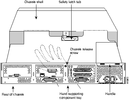
Step 6 While supporting the component tray with one hand, push down on the safety latch tab while pulling out on the component tray.
Step 7 Set the component tray on your work surface.
 Warning Hazardous voltages may exist in or near the power supply, so use extreme caution when working near the power supply. Before starting any of these procedures, turn off power to the system, unplug the power cord, disconnect any cables at the ports, and connect your ESDpreventive wrist strap.
Follow these steps to remove the component tray from a chassis without a safety latch.
Step 1 Turn OFF the system power.
Step 2 Put on your ESD-preventive wrist strap.
Step 3 Remove all network and power cables.
Step 4 Loosen the (nonremovable) screw in the back of the router chassis, labeled Chassis release screw in Figure 2.
Figure 2 : Component Tray Removal for Chassis Without a Safety Latch
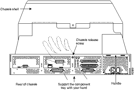
 Warning Support the component tray from underneath, either on your work surface or with your hands, to prevent personal injury. (See the hand in Figure 2.)
Step 5 While facing the chassis rear panel, pull the handle on the right side of the router while supporting the component tray with one hand. Slide the component tray out of the chassis shell.
Step 6 Set the component tray on your work surface.
Follow these steps to remove the Flash EPROM card. (See Figure 3.)
Figure 3 : Flash EPROM Memory Card Location
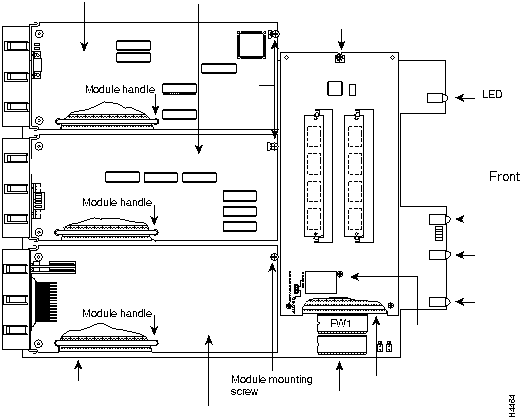
Step 1 Place the component tray in front of you as in Figure 3.
Step 2 Remove the two card mounting screws from the Flash EPROM card and set the screws aside.
 Caution To prevent damaging the Flash EPROM card, handle it by the sides only.
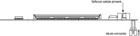
Step 3 Holding the Flash EPROM card by its edges, pull straight up to lift the card out of its connector. (See Figure 4.) The system-memory SIMMs will now be exposed.
Figure 4 : Flash EPROM Card and Connector---Side View
To reinstall the Flash EPROM card, see the section "Replacing Boot ROMs."
If your Cisco 4000 router does not have boot ROMs more recent than Cisco Internetwork Operating System (Cisco IOS) Release 10.2(8), you will need to upgrade them with the boot ROMs provided with the Flash EPROM card. To upgrade the boot read-only memory (ROM) software to a new software image, the existing boot ROMs must be replaced.
Step 1 Open the chassis and expose the boot ROMs following the procedures in the section "Accessing the Internal Components of the Router."
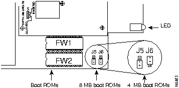
Step 2 After the boot ROMs (FW1 and FW2) on the system card are exposed (see Figure 5), follow the procedures in this section to replace the ROMs.
 Caution The correct placement of the boot ROMs is crucial. If improperly positioned, the new components could be damaged when the system is powered on. Read through all of the instructions before proceeding. To prevent damage to the ROMs from ESD (when handling the system and its components), follow the ESD procedures described earlier. Also, be careful not to damage or scratch the printed circuit card under the ROMs.
Step 3 Locate the boot ROMs, FW1 and FW2. (See Figure 5.)
Figure 5 : Boot ROMs Locations and Boot ROMs Capacity Jumpers
Step 4 Using an EPROM extraction tool or a small flat-blade screwdriver, gently remove the boot ROMs and set them aside.
Step 5 Insert the new boot ROMs in their respective sockets in the orientation shown in
Figure 5 being careful not to bend or crush any of the bottom pins. To straighten out a bent pin, use needlenose pliers. Align the notch in the new ROM with the notch in the ROM socket, ignoring the orientation of the label.
Step 6 Boot ROMs version Cisco IOS Release10.2(8) and higher require setting the boot ROM capacity jumpers, J5 and J6, to the 8 Mb boot ROMs position. (See Figure 5.) To set the boot ROM capacity jumpers to the 8M boot ROMs position, short pins 2 and 3 on J5 and J6, as shown in Figure 5.
Follow these steps to install the Flash EPROM card.
 Caution To prevent damaging the Flash EPROM card, handle it only by the sides.
Step 1 Slip on an ESD wrist strap, ensuring that it makes good skin contact. Connect the equipment end of the wrist strap to the metal back plate of the chassis, avoiding contact with the connectors.
Step 2 Line up the Flash EPROM card with the 96-pin connector (see Figure 4) and screw holes.
Step 3 Holding the Flash EPROM card by its edges, push straight down on the connector (see Figure 4) to insert its connector into the socket on the component tray. (See Figure 3.)
 Caution Be gentle; do not over torque the screws. The maximum screw torque is 7 inch-lb (about what is required to turn a key in an automobile's door lock).
Step 4 Reinstall the two card-mounting screws. (See Figure 3.)
Step 5 Proceed to the section "Replacing the Component Tray."
Follow these steps to replace the component tray in the chassis shell:
Step 1 Reinsert the component tray into the shell, pushing on the back of the tray while at the same time pressing on the chassis release screw (as shown in Figure 1 and Figure 2) with the thumb of your right hand.
Step 2 Retighten the chassis release screw.
Cisco Information Online (CIO) is Cisco Systems' primary, real-time support channel. Maintenance customers and partners can self-register on CIO to obtain additional content and services.
Available 24 hours a day, 7 days a week, CIO provides a wealth of standard and value-added services to Cisco's customers and business partners. CIO services include product information, software updates, release notes, technical tips, the Bug Navigator, configuration notes, brochures, descriptions of service offerings, and download access to public and authorized files.
CIO serves a wide variety of users through two interfaces that are updated and enhanced simultaneously---a character-based version and a multimedia version that resides on the World Wide Web (WWW). The character-based CIO (called "CIO Classic") supports Zmodem, Kermit, Xmodem, FTP, Internet e-mail, and fax download options, and is excellent for quick access to information over lower bandwidths. The WWW version of CIO provides richly formatted documents with photographs, figures, graphics, and video, as well as hyperlinks to related information.
You can access CIO in the following ways:
- WWW:
http://www.cisco.com.
- Telnet:
cio.cisco.com.
- Modem: From North America, 408 526-8070; from Europe, 33 1 64 46 40 82. Use the following terminal settings: VT100 emulation; databits: 8; parity: none; stop bits: 1; and baud rates up to 14.4 kbps.
For a copy of CIO's Frequently Asked Questions (FAQ), contact
ciohelp@cisco.com.
For additional information, contact
cioteam@cisco.com.
Note If you are a network administrator and need personal technical assistance with a Cisco product that is under warranty or covered by a maintenance contract, contact Cisco's Technical Assistance Center (TAC) at 800 553-2447, 408 526-7209, or
tac@cisco.com.
To obtain general information about Cisco Systems, Cisco products, or upgrades, contact 800 553-6387, 408 526-7208, or
csrep@cisco.com.
Copyright 1988-1996 © Cisco Systems Inc.
