|
|
This chapter provides the following instructions:
It also includes:
Follow these guidelines to ensure general safety:
![]()
Follow these guidelines when working on equipment powered by electricity:
ESD is a discharge of stored electricity that can damage equipment and impair electrical circuitry. It occurs when electronic printed circuit cards are improperly handled and can result in complete or intermittent failures.
Always follow ESD prevention procedures when removing and replacing cards. Wear an ESD wrist strap, ensuring that it makes good skin contact. Connect the clip to an unpainted chassis frame surface to safely channel unwanted ESD voltages to ground. To properly guard against ESD damage and shocks, the wrist strap and cord must operate effectively. Use an ohmmeter to check the ESD wrist strap periodically to ensure that the resistor is providing proper ESD protection.
If no wrist strap is available, ground yourself by touching the metal part of the chassis.
You need the following tools and equipment during the unpacking, installation, and maintenance of the IGS:
This section outlines the steps required to open the IGS chassis. In the following discussion, it is assumed that you are looking at the IGS from the front. Use Figure 1-1 as a guide while performing the cover and tray removal procedures.
![]()
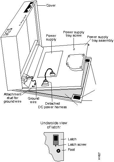
Figure 1-1 Internal View of IGS
The power cable is designed so that if it is installed backwards or offset, +5V is shorted to ground. This enables the protective circuitry on the power supply to protect the system card from reversed voltage. If this happens, you will hear a quiet clicking from the power supply, but you will not hear other noises, such as the fan, and no LEDs will light.
You must replace the EPROMs in the IGS to upgrade your system software. In order to do this, open the IGS (see the section, "Opening the IGS Chassis"). Once the IGS is open to the system card, follow the procedures in this section to replace EPROMs.
After removing the old EPROMs, keep them separate from the new ones to avoid mixing the two sets.
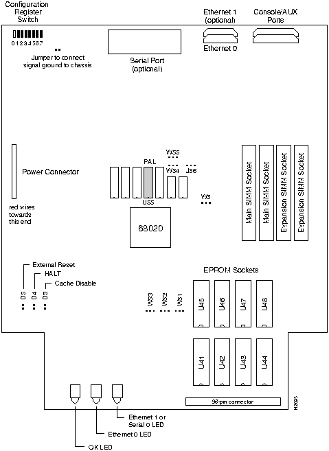
![]()
Figure 1-2 illustrates the IGS card layout. The card is oriented with the front panel LEDs at the bottom of the illustration. Refer to this figure to locate the EPROMs on the system card.
Procedure:
Figure 1-3 shows the appropriate EPROM jumper settings for one--megabit EPROMs. (The number 27C010 is the EPROM chip code for most vendors.)
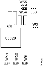
Figure 1-3 Jumper Settings for One--Megabit (27C010) EPROMs
Figure 1-4 shows the appropriate EPROM jumper settings for two--megabit EPROMs. (The number 27C020 is the EPROM chip code for most vendors.)
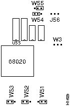
Figure 1-4 Jumper Settings for Two--Megabit (27C020) EPROMs
Figure 1-5 shows the appropriate EPROM jumper settings for four--megabit EPROMs. (The number 27C040 is the EPROM chip code for most vendors.)

Figure 1-5 Jumper Settings for Four--Megabit (27C040) EPROMs
Figure 1-6 shows the appropriate EPROM jumper settings for eight--megabit EPROMs.
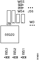
Figure 1-6 Jumper Settings for Eight--Megabit EPROMs
The IGS card comes in a series of hardware revision levels:
The system software reads the revision level and displays the appropriate character in the system banner.
Prior to upgrading the memory, use the show hardware command to determine your hardware revision level as shown in the following example of the IGS system banner:
igs#show hardware


IGS-BX Software, Version 8.3(0.15), ROUTER SOFTWARE


Copyright (c) 1986-1991 by cisco Systems, Inc.


Compiled Wed 14-Aug-91 15:25 by mlb


System Bootstrap, Version 4.3(0.6), ROUTER SOFTWARE


igs uptime is 2 days, 22 hours, 31 minutes


System restarted by reload


System image file is unknown, booted via tftp from 131.108.13.111


cisco IGS (68020) processor (revision I) with 4096K/512K bytes of memory.


Processor board serial number 00043769


DDN X.25 software.


Bridging software.


1 Ethernet/IEEE 802.3 interface.


1 Serial network interface.


16K bytes of non-volatile configuration memory.


Configuration register is 0x0


igs#
In the previous example, the line indicates the hardware revision level (revision I).
cisco IGS (68020) processor (revision I) with 4096K/512K bytes of memory.
Determine your IGS hardware revision level from the system banner display. If your revision level is A-H then follow these directions to upgrade primary memory.
The IGS contains primary and secondary memory. Kilobytes of memory shown in the banner include both primary and secondary memories. Primary memory is implemented with SIMMs (single in-line memory module). Secondary memory is used for packet buffering and consists of 512 kilobytes.
Primary memory may need to be expanded when very large routing tables are used or when many protocols are in use. This might be necessary with configurations in which the IGS is set up as a connection device between large external networks and your internal network. The four--megabyte configuration is necessary to support netbooting.
The standard primary memory configuration of the IGS is half a megabyte of 16-bit-wide RAM. This can be upgraded to one megabyte or four megabytes of 32-bit-wide RAM by the addition of SIMMs. For one megabyte configurations, 256K-by-9 memory modules are used. For four--megabyte configurations, one-megabyte-by-nine modules are substituted. Note that 32-bit-wide memory results in better system performance.
Your memory upgrade kit for IGS Versions A--H from Cisco Systems includes:
Table 1-1 shows the list of Cisco-approved, 256K-by-9, 80-nanosecond SIMM vendors.
Table 1-1 Cisco-Approved, 256K-by-9, 80-Nanosecond SIMMs
| Manufacturer's Name | Manufacturer's Part Number |
|---|---|
| Motorola | MCM94256AS80 |
| Toshiba | THM92500AS-80 |
| Texas Instruments | TM256GU9C-80 |
| Vitelic | V104AJ9S80 |
Table 1-2 shows the list of Cisco-approved, 1-megabyte-by-9, 80-nanosecond SIMM vendors.
Table 1-2 Cisco-Approved, 1-Megabyte-by-9, 80-Nanosecond SIMMs
| Manufacturer's Name | Manufacturer's Part Number |
|---|---|
| Motorola | MCM91000S-80 |
| Toshiba | THM91000AS-80 |
| Texas Instruments | TM024EAD9-80L |
| Mitsubishi | MH1M09A0JA-80 |
Table 1-3 indicates the PAL number and the Cisco part number for each memory size. In each case, insert the PAL into the socket labeled U55.
Table 1-3 Memory Part Number Matrix
| Memory | PAL Number | Cisco Part Number |
|---|---|---|
| 1/2 Mbyte | 16/105 | 17-0526 |
| 1 Mbyte | 16/139 | 17-0729 |
| 4 Mbyte | 16/138 | 17-0728 |
Each memory configuration requires a specific main address decode PAL (location U55). PALs for the one-megabyte and four--megabyte memory options are available from Cisco Systems; part numbers are PAL-1M and PAL-4M, respectively. If you use a PAL set up for less memory than the total of the SIMMs, the IGS will just ignore the additional capacity. For example, if you use a one-megabyte PAL with four megabytes of memory, then the system will only recognize and use one megabyte, and ignore the remaining three megabytes of memory. The position of the jumpers on locations W3 and J56 must also be correct.
If the PAL at U55 and the jumpers do not match, or if one of the SIMMs is missing or poorly seated, then, as the system is attempting to come up, your console output will display:
Bad memory --- unable to read low core
or the IGS will halt after the first two lines of the banner:
System Bootstrap, Version 8.3


Copyright (c) 1986-1991 Cisco Systems, Inc.
If the PAL at location U55 expects less memory space than provided by the SIMMs and the jumpers, the IGS will ignore the extra memory.
Upon boot, your system will indicate the amount of memory it has in the system banner, as in the following example which has 1536 kilobytes of memory (the total of primary and secondary memory).
System Bootstrap, Version 8.3


Copyright (c) 1986-1991 Cisco Systems, Inc.


IGS processor with 1536 KBytes of memory


>
Upgrade your IGS from the standard half--megabyte of primary memory to one megabyte using the Cisco memory upgrade kit. Refer to Figure 1-8 for the standard configuration jumper settings.
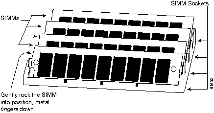
Figure 1-7 Inserting the SIMM into the SIMM Connector
The procedure for upgrading to four megabytes of primary memory is similar to the procedure in the section, "Upgrading to One Megabyte of Primary Memory for Versions
A--H," except if the unit has already been upgraded to one megabyte, then there is no need to change the jumper setting for W3 and J56. In addition, to change to the four--megabyte configuration, remove the existing SIMM cards and replace them with four new cards (one megabyte by nine). The four--megabit PAL is labeled 16/138 or 17-0728.
The jumper settings for both one-- and four--megabyte memory are the same, as noted in Figure 1-8.
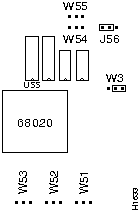
Figure 1-8 Jumper Settings for 1/2--Megabyte Memory
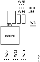
Figure 1-9 Jumper Settings for Both One- and Four-Megabyte Memory
Determine your IGS revision level from the system banner display. If the revision level is I or later, then follow these directions to upgrade primary memory.
The IGS contains primary and secondary memory. The kilobytes of memory shown in the banner include both primary and secondary memory. Primary memory is implemented with SIMMs (Single In-line Memory Module). Secondary memory is used for packet buffering and consists of 512 kilobytes.
You might need to expand primary memory when using very large routing tables or many protocols. This might be necessary with configurations in which the IGS is set up as a connection device between large external networks and your internal network. The fourmegabyte configuration is necessary to support netbooting.
The standard memory configuration of the IGS is half a megabyte of 16-bit-wide RAM. This can be upgraded to one megabyte or four megabytes of 32-bit-wide RAM by the addition of SIMMs. For one-megabyte configurations, 256K-by-9 memory modules are used. For four-megabyte configurations, one megabyte-by-nine modules are substituted. Note that 32-bit-wide memory results in better system performance.
Your memory upgrade kit from Cisco Systems includes:
If the PAL at location U55 and the jumpers do not match, or if one of the SIMMs is missing or poorly seated, as the system is attempting to come up, your console output will display the following:
Bad memory --- unable to read low core
or the IGS will halt after the first two lines of the banner:
System Bootstrap, Version 8.3


Copyright (c) 1986-1991 Cisco Systems, Inc.
If the PAL at location U55 expects less memory space than provided by the SIMMs and the jumpers, the IGS will ignore the extra memory.
Upon boot, your system will indicate the amount of memory it has in the system banner, as in the following example which shows a system with 4096 kilobytes (four megabytes) of primary memory and 512 kilobytes (one-half megabyte) of secondary memory.
System Bootstrap, Version 8.3 ROUTER SOFTWARE


Copyright (c) 1986-1991 cisco Systems, Inc.


cisco IGS (68020) processor (revision I) with 4096K/512K Bytes of memory.


>
To upgrade your IGS, Version I and later, from the standard 1/2-megabyte of primary memory to one megabyte using the Cisco memory upgrade kit, follow these procedures while referring to Figure 1-10, Figure 1-11, and Figure 1-12:
Figure 1-10 shows the jumper settings for 1/2 megabyte of primary memory for Versions I and later.
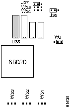
Figure 1-10 Jumper Settings for 1/2-Megabyte Memory
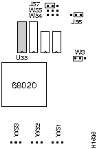
Figure 1-11 Jumper Settings for One-Megabyte Memory

Figure 1-12 Inserting SIMMs into the SIMM Connectors
The procedure for upgrading to four megabytes of primary memory is similar to the previous procedure, with the exception of the position of Jumper J57. In addition, to upgrade to the four--megabyte configuration, remove the existing SIMMs and replace them with four new SIMMs (one megabyte by nine).
The jumper settings for four-megabyte memory are noted in Figure 1-13.
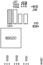
Figure 1-13 Jumper Settings for Four-Megabyte Memory
|
|
Copyright 1988-1995 © Cisco Systems Inc.