|
|
Configuring the LANE and IP Over ATM Clients
This chapter describes how to configure the LAN Emulation and Internet Protocol (IP) over asynchronous transfer mode (ATM) clients on the LightStream 1010 ATM switch. The LAN Emulation and IP over ATM connection can only be used to manage the LightStream 1010 switch.
To configure the LAN Emulation and IP over ATM, complete the tasks in the following sections:
This section describes configuring a port on a switch to allow a classical IP-over-ATM connection to the switch CPU.
The following sections describe configuring the LightStream 1010 ATM switch in either an SVC or PVC environment:
Configure Classical IP over ATM in a SVC Environment
This section describes classical IP over ATM in an SVC environment. It requires a network administrator to configure only the device's own ATM address and that of a single ATM ARP server into each client device.
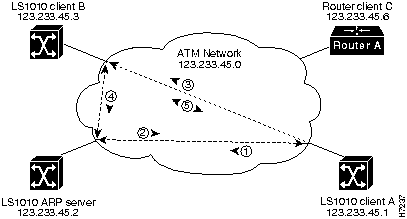
Figure 5-1 describes the steps needed to set up a classical IP over ATM connection between LightStream 1010 ATM switch client A and client B.
Figure 5-1 : Example of Classical IP Over ATM Connection Setup

Configure as an ATM ARP Client
In an SVC environment, configure the ATM ARP mechanism on the interface by performing the following tasks starting in global configuration mode:
Using NSAP Address Example
The following example configures CPU interface 2/0/0 of client A, in Figure 5-1, as the following:
Using ESI Example
The following example configures CPU interface 2/0/0 of client A, in Figure 5-1, as the following:
Configure as an ATM ARP Server
Cisco's implementation of the ATM ARP server supports a single, nonredundant server per logical IP subnetwork (LIS) and supports one ATM ARP server per subinterface. Thus, a single LightStream 1010 ATM switch can support multiple ARP servers by using multiple interfaces.
To configure the ATM ARP server, complete the following tasks starting in global configuration mode:
You can designate the current LightStream 1010 ATM switch as the ATM ARP server in Step 5 by adding the keyword self.
The idle timer interval is the number of minutes a destination entry listed in the ATM ARP server's ARP table can be idle before the server takes any action to time out the entry.
Example
The following example configures CPU interface 2/0/0 of the ARP server, in Figure 5-1, as the following:
To show the IP over ATM interface configuration, use the following command:
Example
In the following example the show atm arp command displays the configuration of the switch interface 2/0/0:
The following example displays the map-list configuration of the switch static map and IP over ATM interfaces:
Configure Classical IP over ATM in a PVC Environment
This section describes classical IP over ATM in a PVC environment. The ATM Inverse ARP mechanism is applicable to networks that use PVCs, where connections are established but the network addresses of the remote ends are not known. A server function is not used in this mode of operation.
In a PVC environment, configure the ATM Inverse ARP mechanism by performing the following tasks, starting in global configuration mode:
Repeat Step 4 for each PVC you want to create.
The inarp minutes interval specifies how often Inverse ARP datagrams are sent on this virtual circuit. The default value is 15 minutes.
Example
The following example configures CPU interface 2/0/0 to use IP over ATM encapsulation as follows:
To show the IP over ATM interface configuration use the following command:
Example
The following example displays the map-list configuration of the switch static map and IP over ATM interfaces:
Configure LAN Emulation Client Example
This section describes configuring a LAN Emulation (LANE) client connection from the LightStream 1010 switch in the headquarters building to the CPU port 2/0/0 of the switch.
Interface 2/0/0 configured as a LANE client will allow configuration of the switch from a remote host.
To configure interface 2/0/0 as a LANE client on the LightStream 1010 switch requires configuring the LANE client as described in the following section.
Using the atm lane client ethernet Command Description
To configure the interface 2/0/0 as a LANE client on LightStream 1010 switch, use the following EXEC commands using the no form of these commands to disable:
Example
The following example configures the LAN emulation configuration server ATM address = 47.0091.0000..., switches to interface configuration mode to configure ATM CPU interface 2/0/0, ATM address = .0800.200C.1001.**, Ethernet LANE client at interface 2/0/0 as an Ethernet connection, with the name = mis,:
To show the LANE client configuration use the following command:
Example
The following example displays the LAN emulation client of the LightStream 1010 switch:
Map a Protocol Address to a PVC
The ATM interface supports a static mapping scheme that identifies the ATM address of remote hosts or switches. This IP address is specified as a PVC or as an NSAP address for SVC operation. Configuration for both PVC and SVC map lists are described in the following sections:
PVC Based Map-List Configuration
This section describes how to map a PVC to an address, which is a required task if you are configuring a PVC.
You enter mapping commands as groups. You first create a map list and then associate it with an interface. Begin the following tasks in global configuration mode:
You can create multiple map lists, but only one map list can be associated with an interface. Different map lists can be associated with different interfaces.
Example
Figure 5-2 describes configuring the following PVC map list:
Figure 5-2 : PVC Map List Configuration Example
Following is an example of the commands used to configure the map list in Figure 5-2.
To show the map list interface configuration use the following command:
Example
The following example displays the map list configuration of the LightStream 1010 switch at interface 2/0/0:
SVC Based Map-List Configuration
This section describes how to map an SVC to an NSAP address, which is a required task if you are configuring an SVC.
You enter mapping commands as groups. You first create a map list and then associate it with an interface. Begin the following tasks in global configuration mode:
You can create multiple map lists, but only one map list can be associated with an interface. Different map lists can be associated with different interfaces.
Example
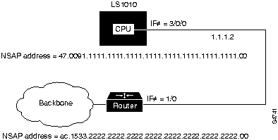
Figure 5-3 describes configuring the following SVC map list:
Figure 5-3 : SVC Map List Configuration Example
Following is an example of the commands used to configure the map list in Figure 5-3.
To show the map list interface configuration use the following command:
Example
The following example displays the map list configuration of the LightStream 1010 switch at interface 2/0/0:
Copyright 1988-1996 © Cisco Systems Inc.
Task
Command
configure1
[terminal]
interface atm 2/0/0[.sub_inter #]
or
Specify the end-system-identifier address of the interface.atm nsap-address nsap-address
atm esi-address esi-address
ip address address mask
atm arp-server nsap nsap-address
exit
See the following note.atm route {addr-prefix2} atm 2/0/0 internal
1 This command is documented in the LightStream 1010 ATM Switch Command Reference publication.
2 First 19-bytes of NSAP address.
Switch(config)#interface atm 2/0/0
Switch(config-if)#$dress 47.0091.8100.0000.1111.1111.1111.1111.1111.1111.00
Switch(config-if)#ip address 123.233.45.1 255.255.255.0
Switch(config-if)#$dress 47.0091.8100.0000.1111.1111.1111.2222.2222.2222.00
Switch(config-if)#exit
Switch(config)#$0.0000.1111.1111.1111.1111.1111.1111 atm 2/0/0 internal
Switch(config)#interface atm 2/0/0
Switch(config-if)#atm esi-address 0041.0b0a.1081.40
Switch(config-if)#ip address 123.233.45.1 255.255.255.0
Switch(config-if)#$7.0091.8100.0000.1111.1111.1111.2222.2222.2222.00
Switch(config-if)#exit
Switch(config)#
Task
Command
configure1
[terminal]
interface atm 2/0/0[.sub_inter #]
or
Specify the end-system-identifier address of the interface.atm nsap-address nsap-address
atm esi-address esi-address
atm arp-server self
ip address address mask
atm arp-server time-out minutes2
exit
See the following note.atm route {addr-prefix3} atm 2/0/0 internal
1 This command is documented in the LightStream 1010 ATM Switch Command Reference publication.
2 When you use this form of the atm arp-server command, it indicates that this interface will perform the ATM ARP server functions. When you configure the ATM ARP client (as described earlier), the atm arp-server command is usedwith a different keyword and argumentto identify a different ATM ARP server to the client.
3 First 19-bytes of NSAP address.
Switch(config)#interface atm 2/0/0
Switch(config-if)#atm esi-address 0041.0b0a.1081.40
Switch(config-if)#atm arp-server self
Switch(config-if)#ip address 123.233.45.2 255.255.255.0
Switch(config-if)#exit
Task
Command
Show the ATM interface ARP configuration.
show atm arp
Show the ATM map list configuration.
show atm map
Switch#show atm arp

Note that a '*' next to an IP address indicates an active call

      IP Address        TTL     ATM Address
ATM2/0/0:
    * 10.0.0.5          19:21   4700918100567000000000112200410b0a108140

Switch#
Switch#show atm map
Map list ATM2/0/0_ATM_ARP : DYNAMIC
arp maps to NSAP 36.0091810000000003D5607900.0003D5607900.00
        , connection up, VPI=0 VCI=73, ATM2/0/0
ip 5.1.1.98 maps to NSAP 36.0091810000000003D5607900.0003D5607900.00
        , broadcast, connection up, VPI=0 VCI=77, ATM2/0/0

Map list ip : PERMANENT
ip 5.1.1.99 maps to VPI=0 VCI=200

Switch#
Task
Command
configure1
[terminal]
interface atm 2/0/0
ip address address mask
atm pvc vpi vci encap aal5snap [inarp minutes]
1 This command is documented in the LightStream 1010 ATM Switch Command Reference publication.
Switch(config)#interface atm 2/0/0
Switch(config)#ip address 11.11.11.11
Switch(config-if)#atm pvc 0 100 encap aal5snap inarp 10 interface atm 0/0/0 50 100
Task
Command
Show the ATM interface ARP configuration.
show atm map
Switch#show atm map
Map list yyy : PERMANENT
ip 1.1.1.2 maps to VPI=0 VCI=200

Map list zzz : PERMANENT

Map list a : PERMANENT

Map list 1 : PERMANENT

Map list ATM2/0/0_ATM_ARP : DYNAMIC
arp maps to NSAP 47.009181005670000000001122.00410B0A1081.40
        , connection up, VPI=0 VCI=85, ATM2/0/0
ip 10.0.0.5 maps to NSAP 47.009181005670000000001122.00410B0A1081.40
        , broadcast, ATM2/0/0

Switch#
Task
Command
configure1
[terminal]
atm lecs-address lecs-address
interface atm 2/0/0[.sub_inter #]
lane client-atm-address atm-address-template
lane client ethernet [elan-name]
1 This command is documented in the LightStream 1010 ATM Switch Command Reference publication.
Switch(config)# atm lecs-address 47.0091.0000.0000.0000.0000.0000.0000.00
Switch(config)# interface atm 2/0/0
Switch(config-if)# lane client-atm-address...0800.200C.1001.**
Switch(config-if)# lane client ethernet mis
Task
Command
Show the LAN emulation client configuration.
show lane client
Switch#show lane client
LE Client ATM2/0/0  ELAN name: alpha  Admin: up  State: operational
Client ID: 2
HW Address: 0061.3e5b.bb02   Type: ethernet             Max Frame Size: 1516
ATM Address: 47.00918100000000613E5BBB01.000011112222.00

 VCD  rxFrames  txFrames  Type       ATM Address
   0         0         0  configure  47.333300000000000000000000.000111222333.00
 104         1        11  direct     47.333300000000000000000000.001122334455.00
 105        15         0  distribute 47.333300000000000000000000.001122334455.00
 106         0        10  send       47.333300000000000000000000.000000111111.00
 107        19         0  forward    47.333300000000000000000000.000000111111.00
 108         5         6  data       47.00918100000000613E5BBB01.00000C523BC8.00

Switch#
Task
Command
configure1
[terminal]
ip host-routing
interface atm card/sub_card/port [.sub_inter #]
ip A.B.C.D mask
map-group name
atm pvc vpi vci [encap aal5lane aal5mux aal5snap] [upc upc] [pd pd] [rx-cttr index] [tx-cttr index] interface atm card/subcard/port[.sub_inter #] vpi vci [upc upc]
exit
ip route A.B.C.D mask [A.B.C.D|atm|ethernet|null]
map-list name
[ip A.B.C.D] [arp atm-nsap atm-vc] [cdp atm-nsap atm-vc] [compressedtcp A.B.C.D] exit-class
exit-class
1 This command is documented in the LightStream 1010 ATM Switch Command Reference publication.

Switch(config)#ip host-routing
Switch(config)#interface atm 2/0/0
Switch(config-if)#ip address 1.1.1.1 255.0.0.0
Switch(config-if)#map-group yyy
Switch(config-if)#atm pvc 0 200 encap aal5snap interface atm 3/0/0 100 300
Switch(config-if)#exit
Switch(config)#ip route 1.1.1.1 255.0.0.0 1.1.1.2
Switch(config)#map-list yyy
Switch(config-map-list)#ip 1.1.1.2 atm-vc 200
Switch(config-map-list)#end
Switch#
Task
Command
Show the ATM interface map list configuration.
show atm map
Switch#show atm map
Map list yyy : PERMANENT
ip 1.1.1.2 maps to VPI=0 VCI=200

Switch#
Task
Command
configure1
[terminal]
ip host-routing
interface atm card/sub_card/port [.sub_inter #]
ip A.B.C.D mask
atm nsap-address 20-octet NSAP address
map-group name
exit
map-list name
[ip A.B.C.D] [arp atm-nsap atm-vc smds] [cdp atm-nsap atm-vc smds] [compressedtcp A.B.C.D] exit-class
exit-class
1 This command is documented in the LightStream 1010 ATM Switch Command Reference publication.

Switch(config)#ip host-routing
Switch(config)#interface atm 2/0/0
Switch(config-if)#ip address 1.1.1.1 255.0.0.0
Switch(config-if)#map-group zzz
Switch(config-if)#atm nsap-address 47.0091.1111.1111.1111.1111.1111.1111.1111.1111.00
Switch(config-if)#exit
Switch(config)#ip route 1.1.1.1 255.0.0.0 1.1.1.2
Switch(config)#map-list zzz
Switch(config-map-list)#ip 1.1.1.2 atm-nsap ac.1533.2222.2222.2222.2222.2222.2222.2222.2222.00
Switch(config-map-list)#end
Switch#
Task
Command
Show the ATM interface map list configuration.
show atm map
Switch#show atm map

Map list yyy : PERMANENT
ip 1.1.1.1 maps to VPI=0 VCI=200
ip 1.1.1.2 maps to VPI=0 VCI=200

Map list zzz : PERMANENT

Switch#
![]()
![]()
![]()
![]()
![]()
![]()
![]()
![]()