
Table of Contents
Router Configuration Tutorial
Router Configuration Tutorial
This tutorial provides information describing how to view and modify router attributes through the Router Configuration windows. Viewing router attributes can be accomplished using the initial baseline scenario created when a baseline is opened and loaded. Therefore, creating a new scenario is not required when viewing router attributes. Modifying router attributes, however, requires the creation of a new scenario.
The following tasks are performed and described:
- a baseline is loaded for simulation
- a baseline topology is constructed
- router configuration settings are examined
- a predicted Routing Table is inspected
- a new scenario is created
- router interface delay metrics are modified
- a static route is created
- router interface failure is induced
- a router passive interface is specified
- a routing algorithm network parameter is modified
- an interface in a router distribution list is specified
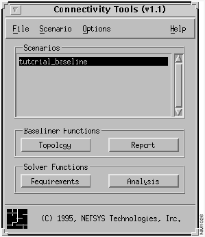
Having proceeded through the steps of creating and opening a baseline, as described in the first tutorial, the Connectivity Tools window, shown in Figure 9-1, is displayed.
Note The Connectivity Tools window's Requirements and Analysis buttons are not implemented in the Connectivity Baseliner. These buttons' features are implemented in the Connectivity Solver.
Figure 9-1 Connectivity Tools Window (Solver): Baseline Scenario Created
- Step 1 Click on the Topology button in the Connectivity Tools window.
- A campus view of the tutorial_baseline scenario's topology is displayed in the Topology window.
- Step 2 Select the View>Flat menu option in the Topology window.
- The topology is displayed in a flat IP view, as shown in Figure 9-2.
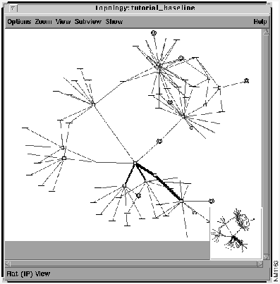
Figure 9-2 tutorial_baseline Topology Window: Flat IP View
- Step 3 With the tutorial_baseline scenario selected in the Connectivity Tools window's Scenarios list, click on the Requirements button.
- To load connectivity requirements for analysis, the Requirements feature is used. Connectivity requirements are created, viewed, loaded, unloaded, deleted, and undeleted using this option. The Requirement Sets window is displayed, as shown in Figure 9-3.
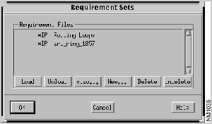
Figure 9-3 Requirement Sets Window
- Step 4 Select the
srb_ring_1857
requirements file set from the Requirement Files list.
- A list of network connectivity requirement file sets, if any exist, containing the connectivity requirements for the tutorial_baseline scenario, is displayed in the Requirement Files list.
- Requirement File entries preceded by an asterisk indicate connectivity requirements implicitly derived from the router configuration files. These connectivity requirement file sets can not be edited or deleted.
- The implicitly derived Routing Loops requirement set is provided to find routing loops caused by IP redistribution. When you select the Routing Loops requirement set and then load it for analysis by clicking on the Load button followed by the OK button, a list of all the redistribution IP routing loops detected during analysis is displayed in the Requirements Analysis window. The results are a set of paths showing the identified routing loops. Each path displays a source address set to a port address of a router involved in the loop and a destination, which is a subnet or end point address, identifying the Routing Table destination involved in the routing loop. The path also shows a set of routers involved in a loop.
- Step 5 Click on the View button.
- The Requirements window is displayed, partially shown in Figure 9-4. The
srb_ring_1857 connectivity requirements are displayed in this window.
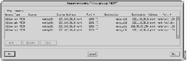
Figure 9-4 Requirements Window: srb_ring_1857
- Step 6 Click on the OK button.
- The Requirements window is dismissed and the Requirement Sets window is displayed again.
- Step 7 Click on the Load button followed by the OK button.
- The implicitly derived srb_ring_1857 connectivity requirements are loaded for analysis. The Requirements Analysis window is displayed, partially shown in Figure 9-5, showing the status of the imposed connectivity requirements on the tutorial_baseline.
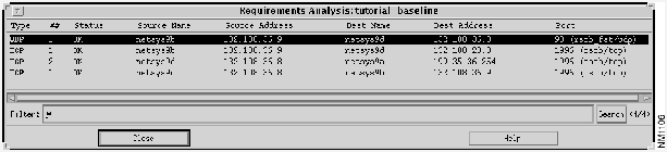
Figure 9-5 Requirements Analysis Window: srb_ring_1857 Analysis Results
- Step 8 Select the entry with
netsys9d
in the Source Name column and
netsys9a
in the Dest Name column in the Requirements Analysis window.
- The corresponding path is highlighted in the Topology window, as shown in Figure 9-6.
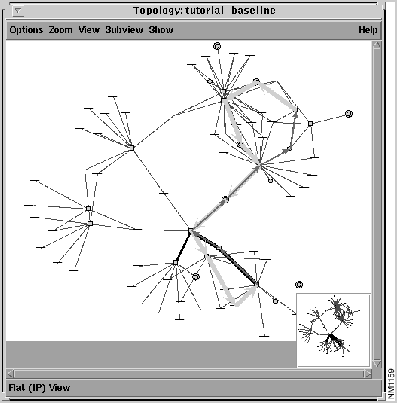
Figure 9-6 Topology Window: srb_ring_1857 Path Highlighted
The thicker highlighted line represents the route from the source router (netsys9d) to the destination router (netsys9a). The thinner highlighted line represents the return path from the destination router (netsys9a) to the source router (netsys9d).
- Step 9 Double-click on the same entry in the Requirements Analysis window.
- The Round Trip Path window is displayed, as shown in Figure 9-7. This window displays information about the two end systems, the number and status of routes available, and a list of the components along the route between the two end systems.
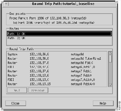
Figure 9-7 Round Trip Path Window: srb_ring_1857 Path
- Step 10 Double-click on a
netsys1
router entry in the Round Trip Path list.
- The netsys1 Router Configuration window, shown in Figure 9-8, is displayed. An external view of the netsys1 router attributes are displayed in this window. Buttons are supplied to change the context to various internal views of the router. Router attribute modifications can only be made within the context of an internal view of a router in a newly created scenario.
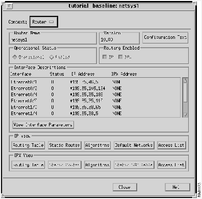
Figure 9-8 Router Configuration Window: netsys1 Router
- Step 11 Click on the IP View Routing Table button.
- The IP Routing Table window, partially shown in Figure 9-9, is displayed. Inspect the Routing Table predicted for netsys1. The following information is provided:
- ALG - the protocol the IP Routing Table entry is derived from
- Dest. Address - IP address of the remote host/device or remote network
- Subnet Mask - IP subnet mask corresponding to the destination address
- Cost - the first number in the bracket is the administrative distance of the routing information source. The second number is the metric for the route.
- Forward To - the local router's interface to use to get to the next router along the path to the destination network
- Next Router - the next router along the path to the destination.
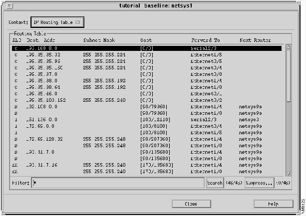
Figure 9-9 Routing Table: netsys1 Router
- Step 12 Scroll through the Routing Table until the entry with Destination Address
199.35.36.0
is found.
- This entry describes a route derived from the IGRP routing algorithm in which the administrative distance is
100
and the metric value is
10000105
. The next router along the route's destination path is netsys9a. There are two interfaces on netsys1 (
Ethernet0/4
and
Ethernet1/5
) the route can pass through to reach netsys9a using the same metric value. The
Ethernet0/4
interface's delay metrics will be modified to show the affect on the netsys1Routing Table and the round trip path.
- Step 13 Select the Scenario>Create New option.
- The tutorial_baseline+ scenario is created, selected, and displayed in the Connectivity Tools window, as shown in Figure 9-10. This newly created scenario is used for simulation and analysis purposes. A new scenario must be created to modify router attributes (e.g. interface operational/failure status, interface metrics, Routing Table updates.)
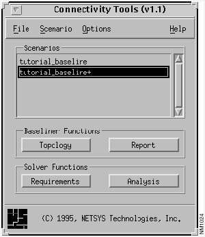
Figure 9-10 Connectivity Tools Window: New Scenario Created
- Step 14 Click on the Analysis button in the Connectivity Tools window.
- The connectivity requirements imposed on the tutorial_baseline+ scenario are assessed and displayed in the Requirements Analysis window, as partially shown in Figure 9-11. As the srb_ring_1857 connectivity requirements are already loaded, the analysis results are the same as previously observed.
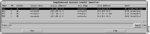
Figure 9-11 Requirements Analysis Window: srb_ring_1857 Requirements Analyzed
- Step 15 Click on the entry in the Requirements Analysis window with the Source name
netsys9d
(132.108.36.8)
and Destination name
netsys9a (199.35.36.254)
.
- The path is highlighted in the tutorial_baseline+ Topology window, as shown in Figure 9-12.
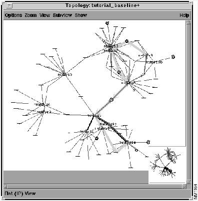
Figure 9-12 Topology Window: New Path Displayed
- Step 16 Double-click on the selected entry in the Requirements Analysis window.
- The Round Trip Path window, shown in Figure 9-13, is displayed. The netsys1 router uses the
Ethernet0/4
(
199.35.35.189
) interface to forward to the next router in the Round Trip Path list. The entry can be found by scrolling through the Round Trip Path list.

Figure 9-13 Round Trip Path Window: tutorial_baseline+ Scenario
- Step 17 Double-click on the
netsys1 Ethernet0/4
entry in the Round Trip Path list.
- The netsys1Router Configuration window is displayed.
- Step 18 Select the Interface entry
Ethernet0/4
from the Interface Descriptions list, then click on the View Interface Parameters button.
- The Interface Parameters window, shown in Figure 9-14, is displayed.
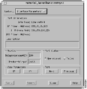
Figure 9-14 Interface Parameters Window: Ethernet0/4 Interface
- Step 19 Change the Delay metric value for
Ethernet0/4
from
100
to
10000
then press Return. Click on the Apply button.
- Step 20 Click on the Analysis button in the Connectivity Tools window.
- The new connectivity requirements imposed on the tutorial_baseline+ scenario are analyzed and displayed in the Requirements Analysis window, as partially shown in Figure 9-15. Note there is only one path available now between routers netsys9d and netsys9a.
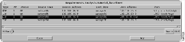
Figure 9-15 Requirements Analysis Window: Reanalysis Performed
- Step 21 Click on the entry in the Requirements Analysis window with the Source name
netsys9d (132.108.36.8)
and Destination name
netsys9a (199.35.36.254)
.
- The new path in the Topology window, shown in Figure 9-16, is highlighted.
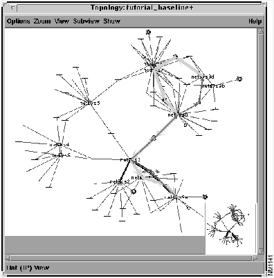
Figure 9-16 Topology Window: New Path Highlighted
- Step 22 Verify a new path has been taken by examining the Round Trip Path window.
- Note router netsys1 now forwards through the
Ethernet1/5
(
199.35.35.37
) interface to reach netsys9a, as shown in Figure 9-17.
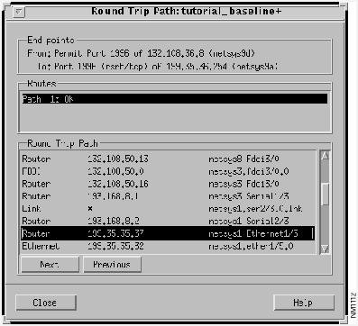
Figure 9-17 Modified tutorial_baseline+ Round Trip Path Window
- Step 23 From the netsys1 Interface Parameters window, examine the
Ethernet1/5
(
199.35.35.37
) interface to verify that its Delay Metric value (
100
) is less than the
Ethernet0/4
interface's Delay Metric value (
10000
).
- Step 24 Select the IP View Routing Table button in the netsys1 Router Configuration window.
- Verify the Destination Address
199.35.36.0
Routing Table entry, partially shown in Figure 9-18, lists
Ethernet1/5
as the interface to be used along the path to the destination (netsys9a).
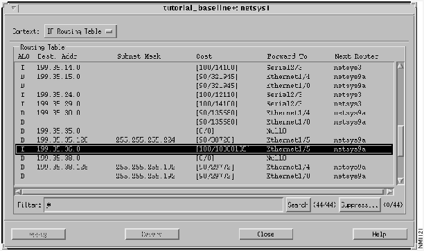
Figure 9-18 Modified netsys1 Routing Table
In this section of the tutorial, a new "what-if" scenario is created by adding an IP Static Route to the netsys1 router's configuration. The result includes an update to netsys1's IP Routing Table and a new path taken to the destination. This tutorial starts from where the last tutorial ended, in the netsys1 IP Routing Table window. Note the route to the destination network
199.35.36.0
is forwarded through the
Ethernet1/5
interface to reach router netsys9a.
- Step 1 Select the Context>Router option in the IP Routing Table window.
- The IP Routing Table window is dismissed and the netsys1 Router Configuration window is displayed.
- Step 2 Click on the IP View Static Routes button.
- The IP Static Routes window, shown in Figure 9-19, is displayed. Notice no IP static routes are currently configured for the netsys1 router.
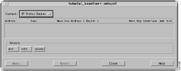
Figure 9-19 Static Routes Window
- Step 3 Click on the Add button in the IP Static Routes window.
- The Edit IP Static Routes List window, shown in Figure 9-20, is displayed.
- Step 4 Enter the destination address (
199.35.36.254
) in the Destination Address field and the address mask (
255.255.255.254
) in the Destination Mask field.
- For this example, a static route is added to the netsys9a router's destination interface (
199.35.36.254
). The route follows the path from the netsys1 router to the netsys9a router's incoming
Ethernet2/4
(
199.35.38.6
) interface.
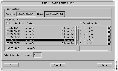
Figure 9-20 Edit IP Static Routes List Window
- Step 5 Click on the OK button.
- The static route is added to the list of static routes, as shown in the IP Static Routes window in Figure 9-21.
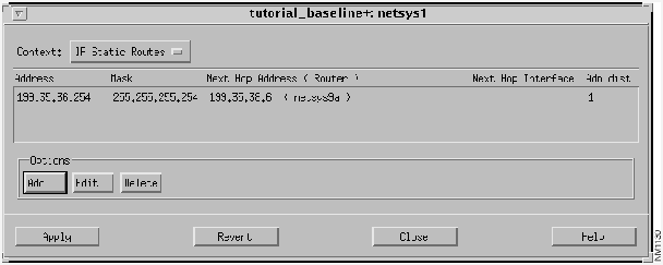
Figure 9-21 Modified IP Static Routes Window
- Step 6 Verify the static route entry, then click on the Apply button.
- The new static route is added to the current netsys1 router configuration. Next, the affect this router configuration change has on the tutorial_baseline+ scenario is examined.
- Step 7 Click on the Analysis button in the Connectivity Tools window.
- Step 8 Click on the entry in the Requirements Analysis window with the Source name netsys9d and Destination name netsys9a.
- The new path in the Topology window is highlighted.
- Step 9 Verify a new path has been taken by examining the Round Trip Path window.
- Note router netsys1 now forwards through interface
199.35.38.5
to reach the netsys9a router's input interface
199.35.38.6
.
- Step 10 Examine the entry in the netsys1 IP Routing Table window.
- Note the "S" in the netsys1 IP Routing Table entry, shown in Figure 9-22, indicating the route to netsys9a over the
Ethernet1/4
interface is a static route with a default administrative distance cost of 1.
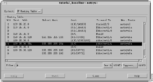
Figure 9-22 Modified netsys1 Routing Table with Static Route Entry
In this example, a new "what-if" scenario is created to introduce a router port failure on the netsys1 router thereby altering the route to the destination (netsys9a). This tutorial focuses on the paths between the netsys3, netsys1, and netsys9a routers.
- Step 1 Click on the IP View Routing Table button in the netsys1 Router Configuration window.
- Note the Routing Table entry for destination address
199.35.36.254
indicates the route is forwarded to the netsy9a router through the
Ethernet1/4
interface.
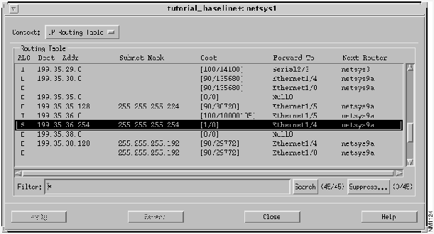
Figure 9-23 IP Routing Table: netsys1 Router
- Step 2 Select the
Ethernet1/4
entry from the Interface Descriptions list in the netsys1 Router Configuration window then click on the View Interface Parameters button.
- The netsys1Interface Parameters window, shown in Figure 9-24 is displayed.
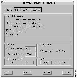
Figure 9-24 Interface Parameters Window: Ethernet1/4 Interface
- Step 3 Click on the Port Status Failed button then click on the Apply button.
- This introduces a failure on the netsys1 router's
Ethernet1/4
interface.
- Step 4 Click on the Analysis button in the Connectivity Tools window.
- Step 5 Click on the entry in the Requirements Analysis window with the Source Name netsys9d and Destination name netsys9a.
- The new path (bypassing the
Ethernet1/4
interface on router netsys1) is highlighted in the Topology window, as shown in Figure 9-25.
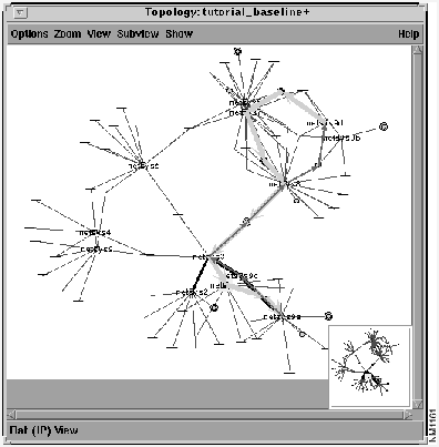
Figure 9-25 Topology Window: netsys1 Ethernet1/4 Failure
- Step 6 Double-click on the same entry in the tutorial_baseline+ Requirements Analysis window.
- The Round Trip Path window, shown in Figure 9-26 is displayed. Examine the updated round trip path components list in the Round Trip Path pane.
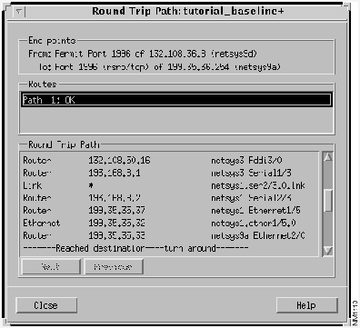
Figure 9-26 Round Trip Path Window: After netsys1 Ethernet1/4 Failure
- Step 7 Examine the IP Routing Table window for router netsys1.
- Note the Routing Table entry for destination address
199.35.36.254
is no longer in existence, as shown in Figure 9-27.
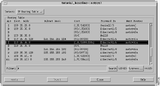
Figure 9-27 netsys1 IP Routing Table: Modified Entry
In this example, a new "what-if" scenario is created showing the effects on the path to the destination when an interface is added to a router's Passive Interface list. A router interface specified as a passive interface is disabled from sending routing updates.
- Step 1 Reset the delay metric for the netsys1 router's
Ethernet0/4
interface to
100
, press Return, then click on the Apply button.
- Follow the steps described earlier in this tutorial where the delay metric was changed from
100
to
10000
.
- Step 2 Delete the netsys1 router's IP static route to destination address
199.35.36.254
then click on the Apply button.
- Follow the steps described earlier in this tutorial where the static route was created.
- Step 3 Set the netsys1 router's
Ethernet1/4
serial interface back in operation by clicking on the Port Status Operational button then click on the Apply button.
- Step 4 Click on the Analysis button in the Connectivity Tools window.
- Step 5 Click on the entry with the Source name netsys9d and Destination name netsys9a.
- The path is highlighted in the Topology window, as shown in Figure 9-28. Examine the Round Trip Path window and note the path taken.

Figure 9-28 Topology Window
- Step 6 Click on the IP View Algorithms button in the netsys1 Router Configuration window.
- The IP Routing Algorithms window, shown in Figure 9-29, is displayed. Display the netsys9a IP Routing Algorithms window, shown in Figure 9-30, using the same method. The IP Routing Algorithms supported by the netsys1 and netsys9a routers are displayed in the Algorithms list in the IP Routing Algorithms window.
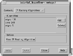
Figure 9-29 netsys1 IP Routing Algorithms Window
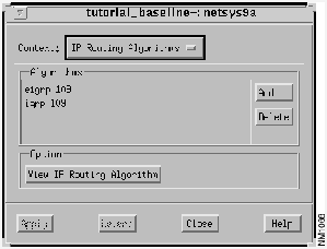
Figure 9-30 netsys9a IP Routing Algorithms Window
- Step 7 Select the Algorithms entry
igrp
109
then click on the View IP Routing Algorithm button, in both windows.
- The netsys1 IGRP 109 window, partially shown in Figure 9-31, is displayed and the netsys9a IGRP 109 window, partially shown in Figure 9-32, is displayed. Note both routers exchange their IGRP routing updates via network
199.35.35.0
as indicated in the Networks pane. Refer back to the Topology window to see how the path goes through subnet
199.35.35.32
. This is possible since router netsys9a advertises the route through that subnet from the
Ethernet2/0
interface.
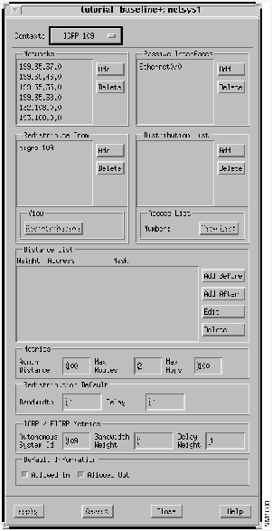
Figure 9-31 netsys1 IGRP 109 Window
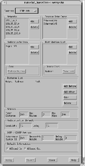
Figure 9-32 netsys9a IGRP 109 Window
- Step 8 Click on the Passive Interfaces Add button in the netsys9a Algorithms window.
- The Edit Passive Interface List window, shown in Figure 9-33, is displayed. Disable interface
Ethernet2/0
from sending IGRP routing updates to router netsys9c via subnet
199.35.35.32
.
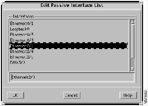
Figure 9-33 Edit Passive Interface List Window
- Step 9 Select the
Ethernet2/0
interface then click on the OK button.
- Step 10 Confirm the Passive Interfaces list for router netsys9a has been updated, then click on the Apply button in the Algorithms window.
- The modified IGRP 109 window is displayed, as partially shown in Figure 9-34.
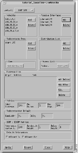
Figure 9-34 Modified netsys9a IGRP 109 Window
- Step 11 Click on the Analysis button in the Connectivity Tools window.
- Step 12 Click on the entry with the Source Name netsys9d and Destination name netsys9a.
- The new path is highlighted in the Topology window, as shown in Figure 9-35.
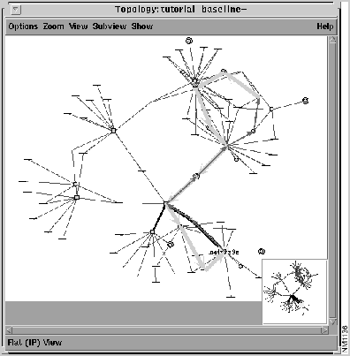
Figure 9-35 Modified Topology Window
- Step 13 Examine the updated Round Trip Path window to verify the new path to the destination.
In this example, a new "what-if" scenario is created describing how to modify the Routing Algorithm Networks list to change the route to the destination. The Networks pane in the Routing Algorithm Window lists the networks a router is directly connected to. The routing algorithm uses this information to update a router's Routing Table.
- Step 1 Examine the netsys1 IP Routing Table.
- Note the current routing entry for destination network
199.35.36.0
forwards the route through the
Ethernet0/4
interface to reach router netsys9a, as shown in Figure 9-36.
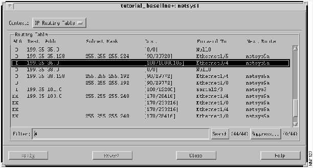
Figure 9-36 netsys1 Routing Table: Ethernet0/4 Interface Entry
- Step 2 Select network address
199.35.35.0
from the Networks pane in the netsys1 IGRP 109 Routing Algorithm window, click on the Delete button, then click on the Apply button.
- The netsys1 IGRP 109 window is partially shown in Figure 9-37.
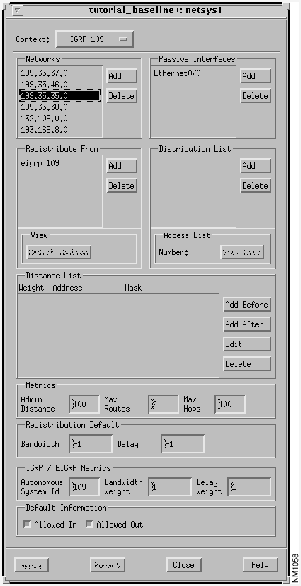
Figure 9-37 netsys1 IGRP 109 Window: Networks List
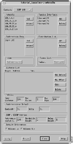
Figure 9-38 netsys9a IGRP 109 Window: Networks List
- Step 3 Click on the Networks Add button in the netsys9a IGRP 109 Algorithm window.
- The Edit Network List window, shown in Figure 9-39, is displayed. Select network address
199.35.46.0
from the Network Addresses list.
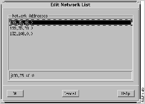
Figure 9-39 Edit Network List Window: netsys9a Router
- Step 4 Click on the OK button.
- The
199.35.46.0
network address is added to the Networks list in the netsys9a IGRP 109 Algorithm window, as partially shown in Figure 9-40.
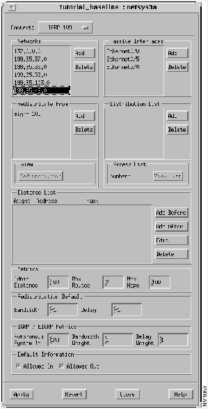
Figure 9-40 Modified netsys9a IGRP 109 Window
- Step 5 Click on the Analysis button in the Connectivity Tools window.
- Step 6 Click on the entry with the source name netsys9d and destination name netsys9a in the tutorial_baseline+ Requirements Analysis window.
- The new path is highlighted in the Topology window, as shown in Figure 9-41.
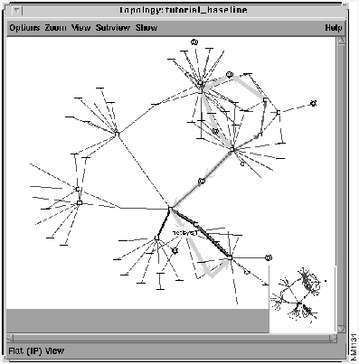
Figure 9-41 Topology Window: Modified Path
- Step 7 Examine the updated Round Trip Path window to verify the new path to the destination.
- Step 8 Reinspect the netsys1 IP Routing Table window to verify the updated destination network (
199.35.36.0
) entry.
- The netsys1 Routing Table is shown in Figure 9-42. Note the current routing entry for destination network
199.35.36.0
forwards the route through the
Ethernet0/1
interface to reach router netsys9a. Initially, the
Ethernet0/4
interface was used to reach router netsys9a.
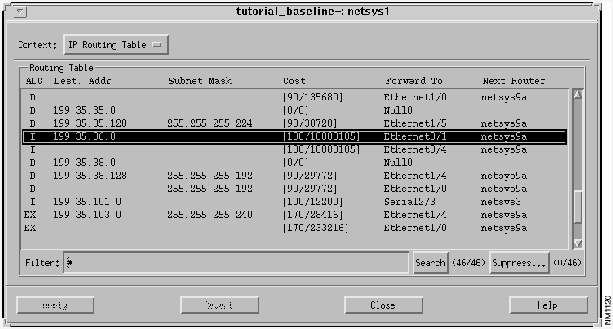
Figure 9-42 Updated netsys1 Routing Table
In this example, a new "what-if" scenario is created showing the effects on the destination path when an interface is added to a router's Distribution List. The Distribution List allows the specification of a router interface to filter inbound and/or outbound routing updates according to an access list.
- Step 1 Click on the netsys1 IGRP 109 Routing Algorithms window's Add button in the Distribution List pane.
- The Edit Distribution List window, shown in Figure 9-43, is displayed allowing you to add a new router interface to the router's distribution list.
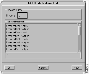
Figure 9-43 Edit Distribution List Window
- Step 2 Select the
Ethernet0/1
input
interface.
- The
Ethernet0/1
input
interface was selected in order to filter incoming routing updates.
- Step 3 Specify an access list number (
10
) then click on the OK button.
- Valid standard IP access list numbers range from 1 through 99.
- Step 4 Verify the Distribution List pane in the IGRP 109 Algorithm window has been updated, then click on the Apply button.
- The modified netsys1 IGRP 109 Algorithms window is partially displayed in Figure 9-44.
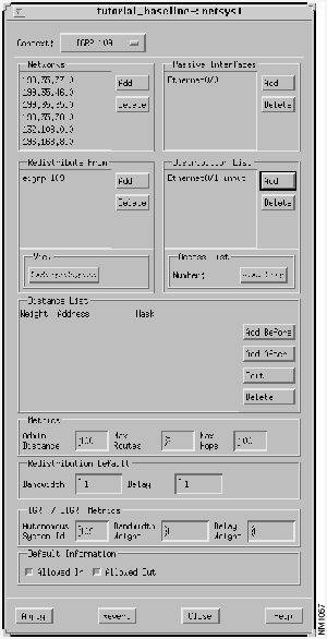
Figure 9-44 netsys1 IGRP 109 Algorithms Window: Modified Distribution List
- Step 5 Select the
Ethernet0/1
input
entry in the Distribution List, then click on the access list View List button.
- Examine the access list associated with the
Ethernet0/1
Distribution Filter List entry. The Distribution Filter List Window, shown in Figure 9-45, is displayed showing the existing access list entries. In this example, all input routing updates coming into the
Ethernet0/1
interface are blocked.
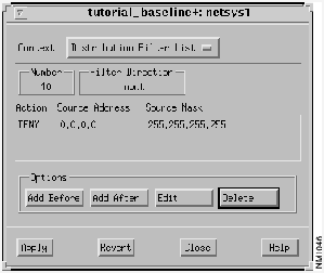
Figure 9-45 Distribution Filter List Window
- Step 6 Repeat the previous steps using the netsys1 EIGRP 109 Algorithm window.
- As the netsys1 and netsys9a routers pass routing updates via the EIGRP 109 routing algorithm as well as the IGRP 109 routing algorithm, the same interface added to the netsys1 IGRP 109 Distribution List must be added to the netsys1 EIGRP 109 Distribution List.
- Step 7 Click on the Analysis button in the Connectivity Tools window.
- Step 8 Click on the entry with the source name netsys9d and destination name netsys9a.
- The new path is highlighted in the Topology window, as shown in Figure 9-46.

Figure 9-46 Topology Window: Distribution Filter List Modified
- Step 9 Examine the updated Round Trip Path window to verify the new path to the destination.
- Step 10 Inspect the netsys1 IP Routing Table window to verify the updated destination network
199.35.36.0
entry.
- The netsys1 Routing Table Window is displayed in Figure 9-47. Note the netsys1
Ethernet0/4
interface is now used as the forwarding interface to destination network
199.35.36.0
instead of the
Ethernet0/1
interface.
Ethernet0/1
now filters out all incoming route updates.
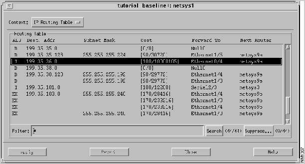
Figure 9-47 Modified netsys1 Routing Table Window
Copyright 1988-1995
©
Cisco Systems Inc.