This chapter presents an overview of the Cisco 12008 Gigabit Switch Router.
The following sections are included in this chapter:
Cisco Systems' new family of Internet switching and routing products, referred to collectively as the Cisco 12000 Series Gigabit Switch Routers, consists of the following models:
- Cisco 12012 Gigabit Switch Router--A 12-slot version that supports IP datagram switching capacities ranging from 15 to 60 Gbps.
- Cisco 12008 Gigabit Switch Router--An 8-slot version that supports IP datagram switching capacities ranging from 10 to 40 Gbps. The Cisco 12008 is the subject of this document.
- Cisco 12004 Gigabit Switch Router--A 4-slot version that supports an IP datagram switching capacity of 5 Gbps.
The architecture of the Cisco 12000 Series Gigabit Switch Routers provides the following networking capabilities and features:
- Scalable bandwidth--Supports high-speed transmission of IP datagrams through use of the following Cisco 12000 series line cards:
- Quad OC-3c/STM-1c Packet-Over-SONET (POS)
- OC-12c/STM-4c Packet-Over-SONET (POS)
- OC-12c/STM-4c Asynchronous Transfer Mode (ATM)
- The network interfaces reside on these line cards, providing connectivity between the router's switch fabric and external networks.
- Scalable performance--Supports multi-gigabit bandwidth switching capacities ranging from 5 to 60 Gbps, providing high-performance support for IP-based networks and wide-area networks (WANs).
- Scalable services--Supports sophisticated congestion management, multicast services, and quality-of-service (QOS) features.
- Carrier-class design--Supports extensive SONET/Synchrononous Digital Hierarchy (SDH) integration; supports a hot-swapping capability for field-replaceable units (FRUs).
The networking capabilities and features of the Cisco 12000 series of routers make them ideally suited to meet the needs of the following classes of users:
- Internet service providers (ISPs)
- Carriers providing Internet services and utilities
- Competitive access providers (CAPs)
- Enterprise wide-area network (WAN) backbones
- Metropolitan-area network (MAN) backbones
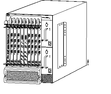
The Cisco 12008 router incorporates a high-speed switching fabric that provides high data-handling capacities for IP-based local- and wide-area networks. Figure 1-1 is a front view of the Cisco 12008 router.
All of the router's major components and FRUs are accessible from the front of the router enclosure, making the router easy to install, configure, and maintain.
Figure 1-1: Cisco 12008 Gigabit Switch Router
The Cisco 12008 supports the following features:
- Online insertion and removal (OIR) capability--This feature allows you to insert or remove the following router components:
- Power supplies--One AC-input power supply or one DC-input power supply is a required router component. You can remove or replace a power supply, without disrupting system operations, only if a second (redundant) unit of the same type is installed in the system.
- The power supplies of both types are hot-swappable, load-sharing units. In a system equipped with two AC-input power supplies or two DC-input power supplies, if one of the units fails or if the power source for one of the units fails, the surviving power supply continues to operate to sustain normal router operations.
Note The Cisco 12008 does not support a mixture of AC-input and DC-input power supplies.
- Cisco 12000 series line cards--Any line card supported by the Cisco 12008 router can be inserted into or removed from the router with no disruption to system operations.
- However, the functions performed by the removed card are lost to the system temporarily until the card is either reinstalled or replaced by a like (and identically configured) line card.
- Gigabit Route Processor (GRP)--As a required router component, a GRP can be removed and replaced, but you must power down the router before doing so.
- A GRP must be installed and operational at all times for normal system operations to be sustained.
- Clock and scheduler card (CSC)--Also a required component, a CSC can be removed and replaced, without disrupting normal system operations, only if a second (redundant) CSC is installed in the system.
- One CSC must be present and operational at all times to maintain normal system operations.
- Switch fabric card (SFC)--An optional set of three SFCs can be installed in the router at any time to provide additional switch fabric to the router. These cards increase the data handling capacity of the router.
- Any one or all of the SFCs can be removed and replaced at any time without system operations being disrupted or the router being powered down.
- For the length of time that any SFC is not functional, its switch fabric is lost to the router as a potential data path for the router's data handling and switching functions.
- Separately orderable documents called configuration notes or replacement instructions are available for each of the FRUs described previously. These documents provide installation, removal, replacement, and configuration instructions for the FRUs.
- Environmental monitoring system--The maintenance bus (MBus) facility of the Cisco 12008 functions as an environmental monitoring system for the router, enabling the router to monitor itself and to alert site personnel to adverse electrical events or environmental conditions.
- MBus software running in the GRP, in combination with LEDs on the CSC faceplate, keep site personnel informed regarding the operational state of the router.
- By signaling alarm conditions, such as component overheating or out-of-tolerance voltages, the router enables you to resolve adverse environmental conditions before operational limits are exceeded, thus preventing the router from shutting down.
- The MBus facility of the router is described in greater detail in the section entitled "Cisco 12008 Environmental Monitoring Facility" on page 64.
- Downloadable software--This feature allows you to remotely load new operational software into Flash memory on the GRP without physically accessing the router. Thus, you can quickly, easily, and reliably perform software upgrades at any time.
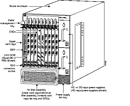
The Cisco 12008 is a modular system consisting of the elements shown in Figure 1-2.
The following sections describe the major elements of the Cisco 12008 in greater detail.
Figure 1-2: Major Components of the Cisco 12008
The outer shell of the Cisco 12008 is a rigid, sheet metal structure with the following dimensions:
- Width--17.4 inches (44.6 cm)
- Depth--21.2 inches (54.4 cm)
- Height-- 24.8 inches (63.6 cm)
This enclosure, which houses all of the router's internal components, can be mounted in a telco rack or a four-post equipment rack, or the enclosure can be used as a freestanding unit.
The design of the enclosure permits front accessibility of all router components. All router components plug into a backplane that provides operating power for the components and interconnects them with each other.
The backplane, which is covered by a sheet metal panel that helps to completely enclose the rear of the router, incorporates a nonvolatile random access memory (NVRAM) module that stores the backplane serial number for identification and revision control purposes. The contents of the NVRAM module are accessible from any line card slot.
The cable-management system provides an orderly and convenient way for you to manage the network interface cables running to and from the receive and transmit ports of installed line cards.
Consisting of a cable-management tray and a vertical cable-management bracket (one bracket for each installed line card), the cable-management system (see Figure 1-3) secures the network interface cables neatly in place. The cable management system helps to optimize optical cable performance by eliminating any kinks or sharp bends in the cables. Extreme curvatures in optical cables tend to degrade their performance.
The elements of the cable-management system are shown in Figure 1-3 and described briefly in the following sections:
- Cable-management tray--This tray is attached to the router enclosure above the upper card cage.
- The cable management tray enables you to route the line card interface cables to or from the system through the left side of the tray, keeping the cables organized, out of the way, and free of kinks or sharp bends.
- You direct the cables down to the individual ports on each line card, gauging cable length appropriately to minimize slack in the cable before connecting it to a given port.
Figure 1-3: Cable-Management System
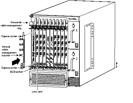
- Vertical cable-management bracket (one per line card)--This bracket is attached to a line card by means of captive installation screws at the top and bottom of the bracket.
- Once an interface cable is connected to its intended line card port, you loop the cable through the cable keeper clip nearest the port of connection and seat the cable in the bottom of the bracket raceway.
- Thus, the vertical cable-management bracket enables you to neatly "dress" all the interface cables in place as you connect them to the individual line card ports.
- Later, when you remove or replace a line card, you need only disconnect the cables from the individual line card ports (leaving the cables intact within the vertical cable-management bracket) and detach the bracket from the line card to be replaced.
- When you install the new line card, you merely reattach the vertical cable-management bracket to the new line card and reconnect the interface cables to the appropriate line card port(s).
The card cage fan tray is located in the lower card cage behind the air filter assembly (see Figure 1-2). This fan tray maintains the operating temperature of the router's electronic circuitry within an acceptable range.
Designed for simplicity, the card cage fan tray incorporates six fans mounted on a sheet metal carrier. The assembly also contains associated wiring and a connector in the back of the unit that enables it to draw operating power through the backplane from a DC-DC converter on the CSC.
Guide rails in the sides of the lower card cage facilitate insertion and removal of the fan tray assembly, which is secured in place by means of a captive installation screw on each side of the metal carrier.
Under normal operating conditions, the variable-speed fans in the card cage fan tray operate at a reduced rate to
- Conserve power
- Reduce noise
- Minimize fan wear
If an overtemperature condition or a fan failure is detected within the router, the master MBus module on the GRP directs the MBus module on the clock and scheduler card (CSC) to increase the operating voltage being delivered to the fan tray, causing the card cage fans to run at "maximum" speed. This increases the volume of cooling air flowing through the router.
If the increased fan speed does not alleviate the overtemperature condition in the affected board, the MBus module on the board shuts down the board's power supply, taking the board offline to protect it from thermal damage.
The MBus facility of the Cisco 12008 router is described in greater detail in the section entitled "Cisco 12008 Environmental Monitoring Facility" on page 64.
The power supply fan tray is in the bottom of the power supply bays (see Figure 1-2). This fan tray maintains the temperature of the installed power supply(ies) within an acceptable range.
Also designed for simplicity, the power supply fan tray incorporates four fans mounted on a sheet metal carrier. The fan tray assembly contains associated wiring and a connector in the back of the unit that enables it to draw operating power through the backplane from a DC-DC converter on the CSC.
A captive installation screw mounted on the fan tray faceplate and guide rails in the sides of the power supply bay facilitate insertion and removal of the unit. Once the unit is inserted, you secure it in place by tightening the captive installation screw clockwise.
Similar to the card cage fan tray, the power supply fan tray is closely tied to the router's overall environmental monitoring system. If an overheating condition or a fan failure is detected within the router, the voltage being delivered to the power supply fans by the CSC is also increased, thereby causing the power supply fans to run at "maximum speed" to increase the volume of cooling passing through the power supply bays.
The Cisco 12008 router can be configured to operate with AC source power or DC source power. You can install one or two AC-input power supplies or one or two DC-input power supplies in the power supply bays located in the right side of the router enclosure (see Figure 1-2).
A single power supply of either type is the standard router configuration. In such a configuration, it is recommended that you install the power supply in the lower bay.
You can install a second (optional and redundant) power supply of the same type for backup purposes.
 | Caution A vacant power supply bay must be covered with a blank filler panel to ensure proper flow of cooling air through the power supply bays and to satisfy EMI compliance requirements. |
Note You cannot use an AC-input power supply in conjunction with a DC-input power supply. Installed power supplies must always be of the same type. Furthermore, you should not install two power supplies of either type unless you intend to actively use both units. In other words, you should not power the router with a single power supply while using the other bay to temporarily or indefinitely "store" an inert unit. Doing so will disrupt the normal flow of cooling air through the router enclosure.
Figure 1-4 shows an AC-input power supply; Figure 1-5 shows a DC-input power supply.
Figure 1-4: AC-Input Power Supply
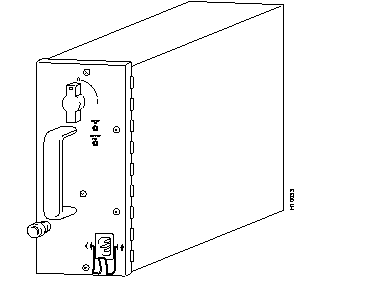
Figure 1-5: DC-Input Power Supply
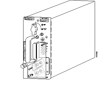
The AC-input and DC-input power supplies operate in either of two modes:
- Standalone mode--In this configuration, only one power supply is installed in one of the two available power supply bays. To remove or replace a single power supply, you must first power down the system.
- Redundant (1+1) mode--In this configuration, two power supplies are installed in the power supply bays, sharing the load current to provide required DC operating voltages to the backplane. If one of the units fails, the surviving power supply takes over to maintain normal system operations.
- The online insertion and removal (OIR) capability of the router enables you to add or remove a redundant power supply without introducing noise in the DC operating voltages being supplied to the backplane.
The AC-input and DC-input power supplies incorporate the following features:
- Onboard maintenance bus (MBus) module--The MBus module on the power supply is a microprocessor-based subassembly that links the power supply to the router's environmental monitoring system.
- The environmental monitoring system includes identical MBus modules on all of the router circuit boards, including the GRP. This system enables you to perform router functions and to respond to alarm conditions (such as overtemperature or overvoltage conditions).
- An alarm condition in the router causes the MBus module on the CSC to illuminate an appropriate LED on the card faceplate, providing a visible notification of the alarm condition.
- Blind mating connector at the back of the unit--Supplies DC operating voltages to the backplane for distribution to the router's electronic and electrical components.
- OIR capability--Enables a second AC-input power supply to be installed in or removed from the router without disrupting normal system operations.
- Temperature sensor--Measures the ambient air temperature of the power supply.
The AC-input and the DC-input power supplies have the following characteristics:
- Width of power supply body--3.5 inches (8.97 cm)
- Width of power supply faceplate--4.0 inches (10.26 cm)
- Height--10 inches (25.64 cm)
- Depth--17.6 inches (45.13 cm)
- Weight (AC-input power supply)--17 lb (7.73 kg)
- Weight (DC-input power supply)--14 lb (6.36 kg)
- Power factor corrector (PFC)--Applicable only to the AC-input power supply, the PFC enables the power supply to accept source AC voltages with the following characteristics: voltages ranging from 180 to 264 VAC, single phase, 47 to 63 Hz.
This section describes the functional elements built into the faceplate of the AC-input power supply (see Figure 1-6).
Figure 1-6: AC-Input Power Supply Faceplate
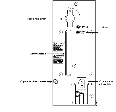
The rotary power switch on the power supply faceplate (see Figure 1-6) applies a source AC voltage to the power supply. This switch also actuates an onboard circuit breaker and a latching mechanism that prevents the power supply from being inserted into or removed from the power supply bay when the switch is in the ON (1) position.
When you rotate the rotary power switch 90 degrees to the ON position, the following DC operating voltages are supplied to the backplane:
Source AC Input Connector
The source AC receptacle on the power supply faceplate (see Figure 1-6) enables an external AC power source to be connected to the power supply. This connector is equipped with a latch that prevents accidental or unintended removal of the AC power cord.
The power specifications for the AC-input power supplies, as well as the source AC power cables available for use with the Cisco 12008 router, are described in Chapter 2 in the section entitled "AC-Powered Systems."
The AC-input power supply faceplate incorporates two LEDs (see Figure 1-6) that provide the following status indications:
- AC INPUT OK--When the rotary power switch is turned ON, this green LED goes on, indicating that source AC power has been applied and that it is within the specified operating range. If this LED does not go on when the rotary power switch is turned ON, it indicates that source AC power is not within the specified operating range or that the LED is faulty.
- OUTPUT FAIL--When the rotary power switch is turned on, this LED goes on momentarily; it should then go off and remain so. If it does not go off, it indicates that the +5.2 VDC or -48 VDC being supplied to the backplane is not within tolerance.
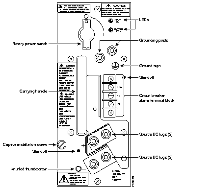
This section describes the functional elements built into the faceplate of the DC-input power supply (see Figure 1-7).
Figure 1-7: DC-Input Power Supply Faceplate
Rotary Power Switch
The rotary power switch on the DC-input power supply performs the same functions as those described in the section entitled "Rotary Power Switch" on page 18 for the AC-input power supply.
The onboard power supply circuit breaker actuated by the rotary power switch on the DC-input power supply incorporates an auxiliary switch that is mechanically linked to (but electrically isolated from) the power supply circuit breaker.
When the power supply circuit breaker is tripped by an overcurrent condition in the power supply, this auxiliary switch moves in unison, sending a signal to the circuit breaker alarm terminal block on the power supply faceplate (see Figure 1-7).
To remotely sense when the power supply circuit breaker has been tripped during an overcurrent condition, you can attach an external alarm-monitoring facility to the alarm terminal block. When the power supply circuit breaker is tripped, power is no longer delivered to the backplane and the router ceases to operate. Hence, if you have attached an external alarm monitoring facility to the alarm terminal block, site personnel can be instantly alerted to this serious fault condition.
Typically, an external alarm-monitoring system incorporates a light panel (visible alarm) or a klaxon (audible alarm) as the means for alerting site personnel to an alarm condition.
To reset the alarm contacts on the alarm terminal block, you must turn the rotary power switch on the power supply OFF and then ON again, much as you would reset any circuit breaker.
Note Any time you manually actuate the rotary power switch, such as when powering down the router, the contacts on the alarm terminal block remain unaffected. Hence, activation of the contacts on the alarm terminal block occurs only during a power supply overcurrent condition. In other words, these contacts are used to provide an immediate, overt indication of a power supply fault condition; they are not used to merely indicate that a circuit breaker has been turned off manually.
The three contacts on the alarm terminal block are labeled as follows:
- COM (Common)--This contact is common to both the Normally Open (NO) and the Normally Closed (NC) contacts.
- NO (Normally Open)--These contacts on the alarm terminal block are open as long as no overcurrent condition is detected in the power supply. When the power supply circuit breaker is tripped during an overcurrent condition, these contacts are closed.
- NC (Normally Closed)--These contacts on the alarm terminal block are closed as long as no overcurrent condition is detected in the power supply. When the power supply circuit breaker is tripped during an overcurrent condition, these contacts are open.
Table 1-1 summarizes the status of the contacts on the alarm terminal block during an overcurrent condition in the power supply.
Table 1-1: Circuit Breaker Status Indicated by the Alarm Terminal Block
| Circuit Breaker Position
| NC Contact
| NO Contact
|
|---|
| OFF (tripped)
| Open
| Closed
|
| ON
| Closed
| Open
|
If you decide to use an external alarm-monitoring facility in conjunction with the alarm terminal block, note that the contacts on the alarm terminal block have a rating of 60 VDC at 1A maximum.
The faceplate of the DC-input power supply incorporates three sets of terminals for connecting source DC power to the power supply (see Figure 1-7). From top to bottom, these terminals are identified as follows:
- Ground
- + (positive)
- - (negative)
The power specifications for the DC-input power supplies, as well as the specifications of the source DC power cables for use with the Cisco 12008 router, are presented in the section entitled "DC-Powered Systems" on page 16 in Chapter 2.
The DC-input power supply faceplate incorporates two LEDs (see Figure 1-7) that provide the following status indications:
- INPUT OK--When the rotary power switch is turned ON, this green LED goes on immediately, indicating that source DC power is applied and that it is within the specified operating range (-40.5 VDC to -75 VDC). If this LED does not go on when the rotary power switch is turned ON, the source DC power being applied to the power supply is not within the normal operating range or the LED is faulty.
- OUTPUT FAIL--When the rotary power switch is turned on, this LED goes on momentarily; it should then go off and remain so. If it does not go off, it indicates that the +5.2 VDC or -48 VDC being supplied to the backplane is not within tolerance.
The upper card cage (see Figure 1-8) contains ten slots that accommodate the following types of cards in the quantities indicated:
- One Gigabit Route Processor (GRP)--A GRP is a standard and required router component; the GRP must be present and operational at all times. It is recommended that you install the GRP in the left-most slot (slot 0) in the upper card cage.
- Either one or two clock and scheduler cards (CSCs)--One CSC is a standard and required router component; one CSC must be present and operational in the router at all times. For redundancy, you can install a second CSC for use as a backup.
- Two dedicated slots in the middle of the upper card cage (CSC0 and CSC1) are reserved for the CSCs. Because the backplane connector of a CSC differs significantly from all other card types, you cannot install a CSC in any other slot.
- Cisco 12000 series line cards--From one to seven line cards of different types can be installed in the line card slots in the upper cage (slots 0 through 3 and slots 4 through 7).
- Although you can install a line card in slot 0, the recommended convention is for the GRP to occupy this slot.
Figure 1-8: Upper Card Cage of the Cisco 12008 Router
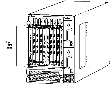
A minimally configured Cisco 12008 contains the following cards in the upper card cage:
- One GRP
- One CSC
- One Cisco 12000 series line card of any type
A Cisco 12008 that is configured for full redundancy contains the following cards in the upper card cage:
- Two GRPs
- Two CSCs
- As many as six Cisco 12000 series line cards of any type and any combination
The following sections briefly describe the cards that you can use to populate the upper card cage.
The Gigabit Route Processor (GRP) is a high-performance circuit board that serves as the main system processor for the Cisco 12008.
This section describes the following facilities, which are built into the GRP:
- Memory components
- System status LEDs
- Soft reset switch
- Personal Computer Memory Card Industry Association (PCMCIA) slots, which are used to transmit data to or from Flash memory cards
- Asynchronous serial ports
- Ethernet port
The faceplate of the GRP is shown in Figure 1-9.
Figure 1-9: GRP Faceplate (Horizontal Orientation Shown)

It is recommended that you install the GRP in the left-most slot (slot 0) in the upper card cage. However, you need not abide by this recommendation. You can install the GRP in any upper card cage slot, except for the two slots in the middle in the upper card cage (CSC0 and CSC1), which are reserved for the CSCs.
The GRP performs the following functions:
- Loading the Cisco IOS software to all of the installed line cards at power up
- Providing a console (terminal) port for configuring the router
- Providing an auxiliary port for other external equipment (such as modems)
- Providing an IEEE 802.3, 10/100 Mbps Ethernet port for Telnet functionality
- Running routing protocols
- Building routing tables and distributing them to line cards
- Providing general system maintenance functions for the router
The GRP communicates with line cards either through the router's switch fabric or its maintenance bus (MBus) facility (see the section entitled "Cisco 12008 Environmental Monitoring Facility" on page 64). The switch fabric provides the data paths for routing table distribution, as well as the means for conveying packets between line cards and the GRP.
The MBus facility enables the GRP to download a system bootstrap image, collect or load diagnostic information, and perform general system maintenance operations.
The GRP contains the following components:
- Processor--An IDT R5000 Reduced Instruction Set Computer (RISC) processor serves as the CPU for the router. The CPU runs at an external bus clock speed of 100 MHz and an internal clock speed of 200 MHz.
- DRAM--Up to 256 MB of parity-protected, extended data output (EDO) dynamic random-access memory (DRAM) is provided in two, 60-nanosecond (ns), dual in-line memory modules (DIMMs). DRAM is used for storing system software, configuration files, and line card routing tables. The minimum DRAM configuration is 64 KB.
- SRAM--512 KB of static random-access memory (SRAM) is used for secondary CPU cache memory functions. SRAM is not user-configurable, nor can it be upgraded in the field.
- NVRAM--512 KB of NVRAM is used for storing router configuration information, system crash information, and ROM monitor variables. NVRAM is not user-configurable, nor can it be upgraded in the field.
- Flash memory SIMM--An 8-MB Flash memory SIMM stores Cisco IOS software images and other user-defined files on the GRP.
- Flash memory cards--PCMCIA Flash memory cards, each with a storage capacity of 20 MB, can be used with the two PCMCIA slots on the GRP to contain Cisco IOS software images and other user-defined files.
- Flash boot ROM--A 512-KB flash EPROM on the GRP stores the ROM monitor boot image.
- Environmental sensors--Two temperature sensors are built into the GRP for environmental monitoring purposes.
- Console and auxiliary EIA/TIA-232 ports--The console port built into the GRP is a DB-25 connector with full DCE functionality. Similarly, the auxiliary port built into the GRP is a DB-25 connector with full DTE functionality.
Note EIA/TIA-232 was previously known as recommended standard RS-232 before its acceptance as a standard by the Electronic Industries Association (EIA) and the Telecommunications Industry Association (TIA).
The Cisco 12008 supports downloadable system software for most Cisco IOS software upgrades, enabling you to remotely download, store, and boot from a new Cisco IOS software image.
Summary of GRP Memory Components
Table 1-2 summarizes the memory components of the GRP.
Table 1-2: GRP Memory Components
| Memory Type
| Memory Size
| Quantity
| Description
|
|---|
| DRAM
| 641 to 256 MB
| 1 or 2
| 64- or 128-MB DIMMs (based on DRAM required) for main Cisco IOS software functions
|
| SRAM
| 512 KB (fixed)2
|
| SRAM for secondary CPU cache memory functions
|
| NVRAM
| 512 KB (fixed)3
|
| MVRAM for the system configuration file
|
| Flash memory SIMM4
| 8 MB
| 1
| Contains Cisco IOS software images and other user-defined files on the GRP
|
| Flash memory (card)
| 20 MB5
| 1 or 2
| Contains Cisco IOS software images and other user-defined files on up to two PCMCIA-based Flash memory cards6
|
| Flash boot ROM
| 512 KB
| 1
| Flash EPROM for the ROM monitor program boot image
|
1
64 MB of DRAM is the default DRAM configuration for the GRP.
2
SRAM is not user configurable or field upgradeable.
3
NVRAM is not user configurable or field upgradeable.
4
The SIMM socket is wired according to Cisco's own design and does not accept industry-standard 80-pin Flash SIMMs.
5
20-MB Flash memory card is the default shipping configuration for the Cisco 12008.
6
A Type 1 or Type 2 PCMCIA card can be used in either PCMCIA slot.
DRAM
The EDO DRAM) on the GRP stores routing tables, networking protocols, and network accounting applications. It also executes the Cisco IOS software.
The standard (default) DRAM configuration for the GRP is 64 MB of EDO DRAM, which you can increase up to 256 MB through available DRAM upgrades.
Two DRAM DIMM sockets are incorporated into the GRP, as shown in Figure 1-10. These sockets, labeled U39 (P4 DRAM bank 1) and U42 (P4 DRAM bank 2), enable you to configure DRAM in increments ranging from 64 MB to 256 MB.
Figure 1-10 shows the location of the two DRAM SIMMs and the Flash SIMM on the GRP.
Figure 1-10: Locations of GRP Memory
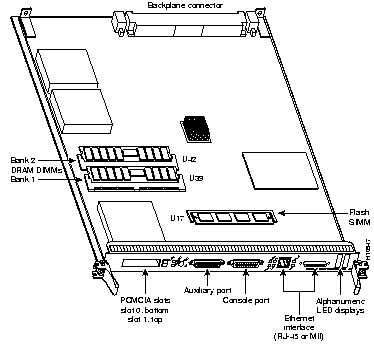
Table 1-3 lists the available upgrade configurations for DRAM on the GRP.
 | Caution To prevent memory problems, DRAM DIMMs must be 3.3 V, 60-nanosecond (ns) devices. Do not attempt to install memory devices in the DIMM sockets that do not meet these requirements. |
Table 1-3: DRAM Configurations
| Total DRAM
| Product Numbers
| DRAM Sockets
| Number of DIMMs
|
|---|
| 64 MB1
| MEM-GRP/LC-64(=)
| U39 (bank 1)
| 1 64-MB DIMM
|
| 128 MB
| MEM-GRP/LC-64(=)
| U39 (bank 1) and U42 (bank 2)
| 2 64-MB DIMMs
|
| 128 MB
| MEM-GRP/LC-128(=)
| U39 (bank 1)
| 1 128-MB DIMM
|
| 256 MB
| MEM-GRP/LC-256(=)
| U39 (bank 1) and U42 (bank 2)
| 2 128-MB DIMMs
|
1
64 MB is the standard (default) DRAM configuration for the GRP.
SRAM
SRAM provides secondary CPU cache memory. The standard GRP configuration is 512 KB. SRAM functions as a staging area for conveying routing table update information to line cards.
NVRAM
The system configuration files, software configuration register settings, and environmental monitoring logs are contained in the 512-KB NVRAM on the GRP. NVRAM is backed up with built-in lithium batteries that have a minimum life of five years, thus ensuring the stability of NVRAM contents.
 | Caution Before replacing the GRP in your system, back up the running configuration file to a Trivial File Transfer Protocol (TFTP) file server or to an installed Flash memory card so that you can later retrieve the file. If you do not save the configuration file, the entire file will be lost (because it is contained in NVRAM on the removed GRP); you will have to reenter the entire configuration file manually. Backing up the configuration file is not necessary if you are only temporarily removing a GRP from the system; the lithium batteries on the GRP enable the configuration file to be retained in memory until you reinstall the GRP. |
Flash Memory
Both the onboard Flash SIMM and the PCMCIA Flash memory cards allow you to remotely load and store multiple Cisco IOS software and microcode images. You can download a new image over the network or from a local server and then add the new image to Flash memory or replace existing files. You can then boot the router either manually or automatically from any of the stored images.
Flash memory can function much like a TFTP server, allowing other servers to boot remotely from stored images or allowing the servers to copy the images into their own Flash memory.
This section describes the two types of system status LEDs used on the GRP: the LED indicators and the alphanumeric LED displays.
- LED indicators--The faceplate of the GRP (see Figure 1-9) incorporates the following LED indicators:
- Two PCMCIA activity LEDs (one per PCMCIA slot)--Each LED goes on when the slot is accessed. The LEDs receive power from the switched slot voltage.
- Four RJ-45 Ethernet port LEDs--These LEDs are used with the RJ-45 Ethernet connector. When the MII Ethernet port is in use, the LEDs are disabled. The LEDs indicate link activity, collision detection, data transmission, and data reception.
- Two RJ-45 or MII Ethernet port select LEDs--These LEDs identify which of two Ethernet connections you selected. When the RJ-45 port is selected, its LED is on, and the MII LED is off. Conversely, when the MII port is selected, its LED is on, and the RJ-45 LED is off.
- Alphanumeric LED displays--These displays are powered by the MBus module, and their contents are driven by MBus software running on the GRP. They are organized as two rows of four characters each.
- These alphanumeric displays provide the following information:
- System status messages displayed during the boot process. During the boot process, the alphanumeric LED displays are controlled directly by the MBus module.
- System status messages displayed after the boot process is completed. After the boot process, the alphanumeric displays are controlled by Cisco IOS software (via the MBus); they display messages designated by the software.
- The alphanumeric displays provide the following types of information:
- GRP status
- System error messages
- User-defined status and error messages
Soft Reset Switch
A soft reset switch is provided on the GRP faceplate to enable you to reset the software running on the R5000 RISC processor of the GRP. You access this switch through a small aperture in the GRP faceplate. To activate the switch, you can press a ball-point pen or similar pointed instrument into the aperture.
 | Caution To prevent system problems or loss of data, use the soft reset switch only at the advice of Cisco service personnel. |
PCMCIA Slots
The GRP incorporates two PCMCIA slots. Either slot can support a Flash memory card or a similar I/O device, provided that the device requires only +5 VDC. The GRP supports Type 1 and Type 2 devices; it does not support +3.3 VDC PCMCIA devices.
Each PCMCIA slot has an ejector button for ejecting a Flash memory card from the slot.
Asynchronous Serial Ports
Two asynchronous serial ports are provided on the GRP faceplate--a console port and an auxiliary port. These ports enable you to connect external devices that you can use to monitor and manage the system.
Ethernet Port
The GRP incorporates an Ethernet port that you can access using either of the following connection types:
Note The RJ-45 and MII receptacles on the GRP faceplate represent two physical connection options for
one Ethernet interface; therefore, you can use
either the MDI RJ-45 connection
or the MII connection, but not both simultaneously.
The heart of the Cisco 12008 is the switch fabric circuitry, which provides synchronized gigabit speed interconnections between the line cards and the GRP. The switch fabric circuitry for the router is incorporated into two cards:
- Clock and scheduler card (CSC)--One CSC installed in the upper card cage is a standard (required) router component. The CSC represents one plane of switch fabric in the router. This card is described in greater detail in the section entitled "Clock and Scheduler Card."
- Switch fabric card (SFC)--You can install a set of three optional SFCs in the lower card cage to increase its switching (data-handling) capacity). Each SFC card represents one plane of switch fabric in the router. This card is described in greater detail in the section entitled "Switch Fabric Cards."
To achieve a fully redundant switch fabric with a switching capacity of 40 Gbps, you can install two CSCs and three SFCs in the router; the second CSC provides redundancy of CSC functions, as well as redundant switch fabric in the event of CSC or SFC failure.
Each CSC or SFC supports an OC-12 switching rate for the router (622 Mbps). By adding the set of three optional SFC cards, you can increase the switching capacity of the router to an OC-48 rate (2.4 Gbps).
Table 1-4 lists the switch fabric bandwidth and the switch card configurations needed to support an OC-12 switching rate or an OC-48 switching rate.
Table 1-4: Switch Fabric Configurations
| Switch Fabric Bandwidth
| Number of CSCs
| Number of SFCs
| Planes of Switch Fabric
|
|---|
| OC-12 nonredundant
| 11
| 0
| 1
|
| OC-12 redundant
| 2
| 0
| 2
|
| OC-48 nonredundant
| 1
| 3
| 4
|
| OC-48 redundant
| 2
| 3
| 5
|
1
A CSC is a required router component.
A minimally configured router (one with a single CSC and no SFCs) supports an OC-12 data rate, but provides no redundancy of CSC functions. Adding a second CSC to a system, as well as the three optional SFCs, has the following effects:
- Increases the router's bandwidth from an OC-12 rate to an OC-48 rate.
- Increases the number of planes of switch fabric available to the router from one to five (with the fifth serving as a redundant plane in the event of failure of a CSC or SFC.
- Provides full redundancy of CSC functions, such as the following:
- System clocking
- Resource allocation
- Scheduling
- Provides full redundancy in the router's fan power and alarm functions.
The CSC is a multi-function circuit board that can be installed in one or both of two reserved slots (CSC0 and CSC1) in the middle of the upper card cage (see Figure 1-2). The standard router configuration requires one CSC in either slot CSC0 or slot CSC1. If you configure your router with a single CSC, it is recommended that you install it in CSC1.
Each CSC is mounted on its own card carrier and incorporates an onboard power supply that takes the -48 VDC supplied by the backplane and converts it into the 3.3 VDC operating voltage required by the card's electronics.
As a multi-function board, the CSC provides the following system services:
These functions are described in the following sections.
A switch plane in the router consists of one OC-12-rate crossbar in the backplane that enables each line card slot in the router to be connected logically to every other line card slot. Line cards installed in any combination of slots in the upper card cage can communicate with each other by means of the router's switch fabric.
The switch fabric of the router constitutes the totality of the possible data paths that can be established through the router. The magnitude of the router's switch fabric (and, hence, its data- carrying capacity) is related directly to the number of switch planes that are made available to the router for data-handling purposes. By installing a second CSC and/or the optional set of three SFCs in the router, you can increase the number of switch planes present in the router, thereby increasing the magnitude of the router's overall switch fabric.
Table 1-5 outlines the possible configurations of CSCs and SFCs and the router switching capacity that results from these configurations.
Table 1-5: Switch Planes Provided by Switch Cards
| Switch Card Type
| Availability
| Number of Switch Planes
| Description
|
|---|
| One CSC
| Standard
| 1
| A single CSC supports an OC-12 data rate for the router, but provides no redundancy in the router's switch fabric.
|
| Second CSC
| Optional
| 1
| A second CSC supports an OC-12 data rate for the router and also provides a redundant plane of switch fabric. If one of the CSCs fails, a fault recovery cutover to the surviving CSC occurs, not only to maintain the router's OC-12 data rate, but also to preserve the system services peculiar to the CSC.
|
| Three SFCs
| Optional
| 3
| The optional set of three SFCs enables the router to support an OC-48 data rate. In an OC-48 rate1 system, no redundancy exists in the switch fabric. However, if a switch plane failure occurs in a fully-redundant2 system, a CSC can take over the functions of either a failed CSC or a failed SFC, not only to maintain the router's OC-48 data rate, but also to preserve the essential CSC system services.
|
1
Router equipped with one CSC and three SFCs.
2
Router equipped with two CSCs and three SFCs.
In addition to providing one plane of switch fabric for the router, the CSC provides numerous other functions and services essential to router operations. Figure 1-11 illustrates the primary functional elements of the CSC.
Figure 1-11: Block Diagram of the CSC
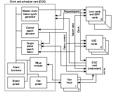
The major functions of each element of the CSC are summarized briefly in the following paragraphs.
- Master clock generator--This function on the CSC provides a clock source to the GRP, all installed switch cards (including the SFCs and a redundant CSC), and all installed line cards. The master clock generator synchronizes the transfer of data through the router's switch fabric.
- In a redundant CSC configuration, the phase of the master clock generator on one card is synchronized with that of the other card. If either clock drifts, the master clock generators on both cards remain tightly aligned.
- Should one of the CSCs fail, the phase lock between the two master clock sources is aborted within nanoseconds, enabling the surviving CSC clock to remain stable and take over master clock duties.
- Frame synchronization generator--This function on the CSC provides a periodic signal to the line cards and switch cards to control data flow.
- In a redundant CSC configuration, either CSC can adopt the frame synchronization phase of the other to ensure phase alignment. The line cards can switch between frame synchronization masters without disruption.
- If the frame synchronization function on one CSC fails, cutover to the surviving frame synchronization generator on the other card occurs within nanoseconds, sustaining system operations.
- Central switch allocator and scheduler--This function on the CSC allocates switching resources to line cards and schedules (arbitrates) the flow of data through the router's switch fabric.
- Switch arbitration begins with a set of requests from line cards to send data through the router's switch fabric. The scheduler plans a set of paths through the switch fabric to carry as much data as possible per unit of time. At the next available time unit, the request to send data is granted, and the data is sent to its destination. The next round of switch arbitration (scheduling) then begins.
- The scheduler also sends switch fabric control information to each switch plane to create appropriate data paths through the switch fabric. When the new data paths are configured into the switch fabric, data begins to flow toward the destination line card(s).
- The central switch allocator and scheduler accepts data transport requests from all line cards (including the GRP), generates grants (accepted data transport requests), and drives all planes of the router's switch fabric.
- Single plane switch fabric--The CSC's single-plane switch fabric provides an OC-12 rate of switching capacity for the router. This switch fabric plane operates under control of the CSC's central switch allocator and scheduler.
- This single switch plane of the CSC can be used alone in a minimum router configuration, or it can be used in combination with another CSC and the three optional SFCs for full switching redundancy. In the latter case, the per line-card slot bandwidth of the router is increased from an OC-12 rate to an OC-48 rate, and the second CSC provides redundancy.
- If any one switch plane fails in a fully redundant switch fabric, the failed plane is shut down, and the router's full data bandwidth is carried by the surviving planes. The fault recovery cutover to another viable switch plane typically occurs without loss of data, because the data path defect is detected while redundancy information is still available, thus enabling error packets to be repaired "on the fly."
The section describes the following housekeeping and alarm monitoring facilities built into the CSC:
- MBus module-- The MBus module on the CSC is a microprocessor-based subassembly that provides housekeeping services required during router power up and initialization. It also supports the alarm monitoring LEDs on the CSC faceplate, as described in the following section.
- The MBus module on the CSC operates partly autonomously and partly under the control of the master MBus module on the GRP.
- A failed MBus module on the CSC is detected by an MBus polling algorithm running in the background on the GRP.
- A failed MBus module detected by this polling algorithm in a redundant CSC configuration causes the master MBus module to execute an administrative cutover to the MBus module on the surviving CSC. This cutover is accomplished with no disruption of normal system operations.
Figure 1-12: CSC Alarm Monitoring Facilities
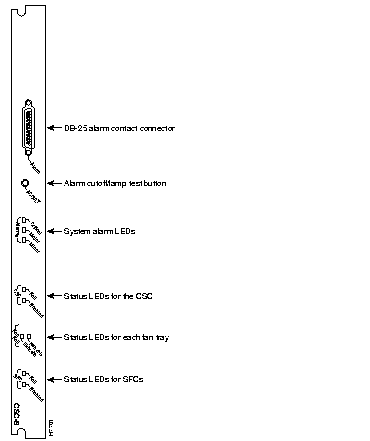
- DB-25 alarm contact connector--A female DB-25 D-sub connector incorporated into the CSC faceplate enables you to attach an external alarm monitoring facility to the router, thus supporting a telco style of handling alarm conditions in the router.
- The alarm signals sent to this DB-25 connector are identical in function to those sent to the system LEDs on the CSC faceplate (see the following section entitled "System Alarm LEDS").
- Any alarm condition in the router that activates one of the system alarm LEDs on the CSC faceplate also energizes an appropriate CSC relay, causing a corresponding signal to be sent to the DB-25 connector. If an external alarm monitoring facility is attached to the DB-25 connector, this signal activates the appropriate external audible or visible alarm.
- An external audible alarm can be reset by clearing the condition that caused the alarm or by pressing the alarm cutoff reset/lamp test (ACO/LT) button on the CSC faceplate (see the following discussion about the ACO/LT button). A visual alarm, however, can be reset only by resolving the problem that caused the alarm condition.
- Only safety extra-low voltage (SELV) external alarm circuits can be connected to the DB-25 connector.
- One external closure sense line, enabling the router to monitor an external event, such as the opening of a cabinet door or the activation of an alarm in associated equipment.
- Alarm cutoff reset/lamp test (ACO/LT) button--If you equip your system with an external alarm monitoring facility, a visible indication can be provided, and/or an audible alarm can be sounded, to immediately notify site personnel of an alarm condition in the router.
- An audible alarm generated by the system continues to sound until you either clear the alarm condition itself or press the ACO/LT button to silence the alarm. Merely pressing this button does not resolve the alarm condition.
- You can test the operability of the LEDs on the CSC(s), the SFC(s), and the power supply(ies), by pressing the ACO/LT button at any time. Doing so causes the LEDs on all these router components to remain lit as long as you hold down the button. However, the LEDs on the SFCs are visible only when the air filter assembly is removed.
- In a system equipped with two CSCs, pressing the ACO/LT button on one CSC is equivalent to pressing this button on either CSC or both CSCs.
- System alarm LEDs--Three system LEDs, labeled critical, major, and minor, are incorporated into the CSC faceplate (see Figure 1-12) to signal the existence of alarm conditions detected in the router by the system's environmental monitoring circuitry.
- During an alarm condition, one of these LEDs goes on to indicate the severity of the detected fault. During a critical alarm, the top LED (Critical) on the CSC faceplate indicates red; similarly, during a major alarm, the middle LED (Major) on the CSC faceplate also indicates red, signifying an alarm condition of lesser severity; finally, during a minor system alarm, the bottom LED (Minor) indicates amber, signifying an alarm condition of least severity.
- At the same time that one of these LEDs goes on to signal the alarm event, an associated alarm relay on the CSC is closed, sending a corresponding signal to the DB-25 alarm contact connector on the CSC faceplate.
- An alarm condition detected in a redundant CSC configuration causes the appropriate relays on both CSCs to close, activating the visible and audible alarm functions of the DB-25 connector on each card.
- When the fault condition is resolved, MBus software running in the GRP automatically clears the fault indication by communicating with the master MBus module, which, in turn, communicates with the MBus module on each circuit board.
- CSC Status LEDs--Two LEDs on the CSC faceplate, the top one labeled FAIL and the bottom one labeled ENABLED, indicate the operational status of the CSC.
- FAN FAIL Status LEDs for each fan tray--Two side-by-side LEDs on the CSC faceplate indicate the operational status of the fan trays.
- The LINECARD LED on the left pertains to the card cage fan tray, and the PWR SPLY LED on the right pertains to the power supply fan tray.
- SFC Status LEDs--Two LEDs at the bottom of the CSC faceplate, the top one labeled FAIL and the bottom one labeled ENABLED, indicate the operational status of the SFCs in the lower card cage (behind the air filter assembly).
- If the FAIL LED goes on, it indicates that one of the three SFCs in the lower card cage has failed. To determine which of the SFCs has failed, you must remove the air filter assembly and examine the status of the LEDs on each SFC.
- Two side-by-side LEDS behind a vertical tab near the center of the SFC (see Figure 1-13) indicate the operational status of the card.
Figure 1-13: Status LEDs on an SFC

DC-DC converters on the CSC provide power for its own circuitry, as well as power for the fan trays. These functions are described briefly in the following sections.
- Board power--A DC-DC converter on the CSC takes the -48 VDC being delivered to the card from the backplane and converts it into the +3.3 VDC required to drive the card's electronic circuity.
- No redundancy is built into the CSC for the +3.3 VDC operating voltage; if the DC-DC converter fails to deliver this voltage, the card shuts down, at which time the redundant CSC, if installed, takes over to maintain normal system operations.
- However, in a nonredundant CSC configuration, the failure of the installed CSC causes the entire system to shut down.
- Fan tray power--The Cisco 12008 router contains two fan trays (see Figure 1-2).
- Control of fan power is initiated at system startup, with the fans running at a slow rate for normal operations. Such operation minimizes fan noise, wear, and power consumption. A DC-DC converter on the CSC provides +20 VDC for slow fan operation and +25 VDC for fast fan operation when an overtemperature condition is sensed in the router.
- Periodically, the master MBus module on the GRP polls the MBus module on each circuit board to determine whether router components are cool enough to warrant keeping the fans running at their minimum rate. If they are not, the master MBus module directs the MBus module on the CSC to increase the operating voltage being delivered to the fan trays, causing the fans to run faster, thus increasing the volume of air being circulated through the router.
- Each fan is monitored separately for failure. A failed fan is not "shut off" in the usual sense; rather, a current-limiting feature in the faulty fan prevents it from interfering with the operation of other fans.
- On failure of a fan in either the card cage fan tray or the power supply fan tray, the CSC increases the voltage being delivered to the surviving fans, causing them to run faster to compensate for the failed fan.
The Cisco 12008 comes equipped with the number and type of line cards that you ordered already installed. Up to seven Cisco 12000 series line cards can be installed in the router to support a variety of physical network media.
The line cards can be installed in upper card cage slots 0 through 3 and slots 4 through 7. Note, however, that it is recommended that the GRP be installed in slot 0. Line cards interface to each other and the GRP through the router's switch fabric.
The following types of line cards are available for use with the Cisco 12008:
- Quad OC-3c/STM-1c POS--4 ports
- OC-12c/STM-4c POS--1 port
- OC-12c/STM-4c ATM--1 port
These cards provide the interfaces to the router's external physical media. They exchange packet data with each other by way of the router's switch fabric.
 | Caution Any unoccupied slot in the upper card cage must have a blank filler panel installed for EMI compliance and to ensure proper air flow through the router enclosure. |
A vertical cable-management bracket attached to the faceplate of each line card enables you to neatly arrange the network interface cables for connection to the individual ports on the line card. The cable-management system is described in detail in the section entitled "Cable-Management System" on page 8.
The online insertion and removal (OIR) capability of the Cisco 12008 enables you to remove and replace a line card while the system remains powered up and operational.
The Cisco 12000 series line cards available for use with the Cisco 12008 router are described briefly in the following sections.
Quad OC-3c/STM-1c POS Line Card
The Quad OC-3c/STM-1c POS line card provides the Cisco 12008 router with four independent Packet-Over-SONET (POS) ports on a single card. The card interfaces with the router's switch fabric and provides four OC-3c/STM-1c SC-duplex SONET connections. These connections are concatenated, which provides for increased efficiency by eliminating the need to partition the bandwidth.
Figure 1-14 shows a high-level block diagram of the Quad OC-3c/STM-1c POS line card; Figure 1-15 shows a front view of the card.
Figure 1-14: Block Diagram of the Quad OC-3c/STM-1c POS Line Card
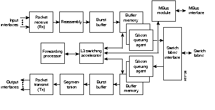
Figure 1-15: Quad OC-3c/STM-1c POS Line Card
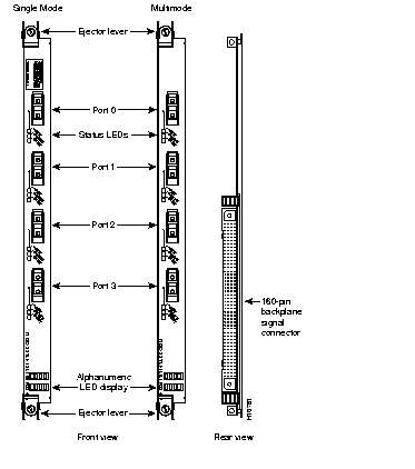
Each Quad OC-3c/STM-1c POS line card incorporates the following major components:
- Transceivers--The single-mode intermediate reach transceiver provides a full-duplex, 155-Mbps, 1300-nm, laser-based SONET/SDH-compliant interface. The multimode transceiver provides a full-duplex, 155-Mbps, 1300-nm, LED-based SONET/SDH compliant interface.
- The SONET specification for fiber-optic transmission defines two types of fiber: single mode and multimode. Signals can travel farther through single mode fiber than through multimode fiber.
- The maximum distance for single-mode installations is determined by the amount of light loss in the fiber path. Good quality single-mode fiber with very few splices can carry an OC-3c/STM-1c signal 9.3 miles (15 km) or more; good quality miltimode fiber can carry a signal up to 1.3 miles (2 km).
- Burst buffers--The Quad-OC3c/STM-1c contains four 128-KB burst buffers. The burst buffer prevents the dropping of packets during instantaneous increases in the number of back-to-back small packets being transmitted at OC-3 line rates.
- Burst buffers are used to achieve high throughput while smoothing out the arriving packet burst for the Layer 3 switch processor.
- Buffer memory--The silicon queuing engine controls the placement of IP packets in buffer memory as well as their removal from buffer memory. The default packet buffer memory is 32 MB, which includes 16 MB of receive (Rx) buffers and 16 MB of transmit (Tx) buffers.
- The buffer memory can be configured to support up to 64 MB of receive buffers and up to 64-MB of transmit buffers. The buffers can support delays comparable to the longest round trip delays measured in the Internet at OC-3c/STM-1c line rates.
- Layer 2 switching accelerator--The Layer 2 switching accelerator assists the forwarding processor. It is a specially designed application-specific integrated circuit (ASIC) that optimizes access to the Layer 2 and Layer 3 information within each packet. At very high line rates, this access process must be executed as rapidly as possible, which is why an ASIC is dedicated to the process.
- Forwarding processor--A forwarding processor makes forwarding decisions based on the information in the Cisco Express Forwarding (CEF) table and the Layer 2 and Layer 3 information in the packet. The GRP constantly updates forwarding information in the forwarding table based on the latest information in the routing table.
- Once the forwarding decision has been made, the silicon queuing engine is notified by the forwarding processor, and the silicon queuing engine places the packet in the proper queue.
- This partitioning between the Layer 2 switching accelerator and the forwarding processor blends the high throughput of hardware-accelerated forwarding with the flexibility of software-based routing.
- Silicon queuing engine--Each line card has two silicon queuing engines: receive and transmit. The receive engine moves packets from the burst buffer to the switch fabric, and the transmit engine moves packets from the switch fabric to the transmit interface.
- When an incoming IP packet is clocked into the silicon queuing engine, the packet's integrity is verified by a check of the CRC. Next, the silicon queuing engine transfers the IP packet to buffer memory and tells the Layer 3 switching accelerator the location of the IP packet.
- Simultaneously, the silicon queuing engine is receiving forwarding information from the forwarding processor. The forwarding processor tells the silicon queuing engine the virtual output queue where the IP packet is to be placed.
- Each virtual output queue represents an output destination (destination line card). This placement of the IP packets in a virtual output queue is based on the decision made by the forwarding processor. There is one virtual output queue for each line card, plus a dedicated virtual output queue for multicast service.
- The transmit silicon queuing engine moves the packet from the switch fabric to the transmit buffer, and then to the transmit interface.
- Switch fabric interface--The switch fabric interface is the same 1.25-Gbps, full-duplex data path to the switching fabric that is used by the GRP. Once a packet is in the proper queue, the switch fabric interface issues a request to the master clock scheduler on the CSC. The scheduler issues a grant and transfers the packet across the switching fabric.
- Maintenance bus (MBus) module--A maintenance bus (MBus) module on the line card responds to requests from the master MBus module on the GRP. The MBus module on the line card reports temperature and voltage information to the master MBus module. In addition, the MBus module on the line card contains the ID-EEPROM, which stores the serial number, hardware revision level, and other information about the card.
- Cisco Express Forwarding (CEF) memory table--Each line card maintains CEF tables. These tables, derived from routing tables maintained by the GRP, are used by the line card processor in making forwarding decisions.
- Large networks may require more DRAM to support large CEF tables. For information on adding memory to a line card, see the document entitled Cisco 12000 Series Gigabit Switch Router Memory Replacement Instructions.
OC-12c/STM-4c POS Line Card
The OC-12c/STM-4c POS line card provides the Cisco 12008 with a single 622-Mbps Packet-Over-SONET (POS) interface. The card provides one OC-12c/STM-4cc SC duplex single-mode or multimode SONET/SDH connection. This connection is concatenated, which provides for increased efficiency by eliminating the need to partition the bandwidth.
Figure 1-16 shows a high-level block diagram of the OC-12c/STM-4c POS line card; Figure 1-17 shows a front view of the card.
Figure 1-16: Block Diagram of the OC-12c/STM-4c POS Line Card
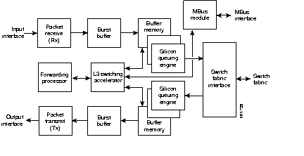
Figure 1-17: OC-12c/STM-4c POS Line Card
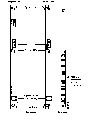
Each OC-12c/STM-4c POS line card incorporates the following primary components:
Each Quad OC-3c/STM-1c POS line card incorporates the following major components:
- Transceivers--The single-mode intermediate reach transceiver provides a full-duplex, 155-Mbps, 1300-nm, laser-based SONET/SDH-compliant interface. The multimode transceiver provides a full-duplex, 155-Mbps, 1300-nm, LED-based SONET/SDH compliant interface.
- The SONET specification for fiber-optic transmission defines two types of fiber: single mode and multimode. Signals can travel farther through single mode fiber than through multimode fiber.
- The maximum distance for single-mode installations is determined by the amount of light loss in the fiber path. Good quality single-mode fiber with very few splices can carry an OC-3c/STM-1c signal 9.3 miles (15 km) or more; good quality miltimode fiber can carry a signal up to 1640 feet (500 m).
- Burst buffers--The burst buffer (512 KB) prevents the dropping of packets during instantaneous increases in the number of back-to-back small packets being transmitted at OC-12c/STM-4c line rates. Burst buffers are used to achieve high throughput while smoothing out the arriving packet burst for the Layer 3 switch processor.
- Buffer memory--The silicon queuing engine controls the placement of IP packets in buffer memory as well as their removal from buffer memory. The default packet buffer memory is 32 MB, which includes 16 MB of receive (Rx) buffers and 16 MB of transmit (Tx) buffers.
- The buffer memory can be configured to support up to 64 MB of receive buffers and up to 64 MB of transmit buffers. The buffers can support delays comparable to the longest round trip delays measured in the Internet at OC-12c/STM-4c line rates
- Layer 2 switching accelerator--The Layer 2 switching accelerator assists the forwarding processor. It is a specially designed application-specific integrated circuit (ASIC) that optimizes access to the Layer 2 and Layer 3 information within each packet. At very high line rates, this access process must be executed as rapidly as possible, which is why an ASIC is dedicated to the process.
- Forwarding processor--A forwarding processor makes forwarding decisions based on the information in the Cisco Express Forwarding (CEF) table and the Layer 2 and Layer 3 information in the packet. The GRP constantly updates forwarding information in the forwarding table, based on the latest information in the routing table.
- Once the forwarding processor makes a forwarding decision, it notifies the silicon queuing engine, and the silicon queuing engine places the packet in the proper queue.
- This partitioning between the Layer 2 switching accelerator and the forwarding processor blends the high throughput of hardware-accelerated forwarding with the flexibility of software-based routing.
- Silicon queuing engine--Each line card has two silicon queuing engines: receive and transmit. The receive engine moves packets from the burst buffer to the switch fabric, and the transmit engine moves packets from the switch fabric to the transmit interface.
- When an incoming IP packet is clocked into the silicon queuing engine, packet integrity is verified by a CRC check. Next, the silicon queuing engine transfers the IP packet to buffer memory and tells the Layer 3 switching accelerator the location of the IP packet. Simultaneously, the silicon queuing engine is receiving forwarding information from the forwarding processor. The forwarding processor tells the silicon queuing engine the virtual output queue where the IP packet is to be placed.
- Each virtual output queue represents an output destination (destination line card). This placement of the IP packets in a virtual output queue is based on the decision made by the forwarding processor. There is one virtual output queue for each line card, plus a dedicated virtual output queue for multicast service.
- The transmit silicon queuing engine moves the packet from the switch fabric to the transmit buffer, and then to the transmit interface.
- Switch fabric interface--The switch fabric interface is the same 1.25-Gbaud, full-duplex data path to the switching fabric that is used by the GRP. Once a packet is in the proper queue, the switch fabric interface issues a request to the master clock scheduler on the CSC. The scheduler issues a grant and transfers the packet across the switching fabric.
- Maintenance bus (MBus) module--A maintenance bus (MBus) module on the line card responds to requests from the master MBus module on the GRP. The MBus module on the line card reports temperature and voltage information to the GRP master MBus module.
- In addition, the MBus module on the line card contains the ID-EEPROM, which stores the serial number, hardware revision level, and other information about the card.
- Cisco Express Forwarding (CEF) memory table--Each line card maintains CEF tables. These tables, derived from routing tables maintained by the GRP, are used by the line card processor to make forwarding decisions.
- Large networks may require more DRAM to support large CEF tables. For information on adding memory to a line card, see the document entitled Cisco 12000 Series Gigabit Switch Router Memory Replacement Instructions.
OC-12c/STM-4c ATM Line Card
The OC-12c/STM-4c ATM line card provides the Cisco 12008 with a 622-Mbps ATM interface. The card interfaces to the router's switch fabric, supports from 10 to 40 Gbps, and provides one OC-12c/STM-4c SC duplex single-mode or multimode SONET/SDH connection. This connection is concatenated, which provides for increased efficiency by eliminating the need to partition the bandwidth.
Figure 1-18 shows a high-level block diagram of the OC-12c/STM-4c ATM line card; Figure 1-19 shows a front view of the card.
Figure 1-18: Block Diagram of the OC-12c/STM-4c ATM Line Card
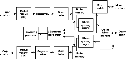
Figure 1-19: Front View of OC-12c/STM-4c ATM Line Card
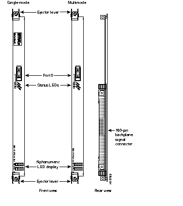
Each OC-12c/STM-4c ATM line card incorporates the following primary components:
- Reassembly and segmentation--The transceivers support packet reassembly (converting ATM cells to packets) and segmentation (converting packets to ATM cells). The transceivers can handle up to 4000 simultaneous reassemblies (based on an average packet size of 280 bytes). In addition, the reassembly application-specific integrated circuit (ASIC) and the segmentation ASIC support up to 15,000 active virtual circuits.
- The SONET specification for fiber-optic transmission defines two types of fiber: single mode and multimode. Signals can travel farther through single mode fiber than through multimode fiber.
- The maximum distance for single-mode installations is determined by the amount of light loss in the fiber path. Good quality single-mode fiber with very few splices can carry an OC-3c/STM-1c signal 9.3 miles (15 km) or more; good quality miltimode fiber can carry a signal up to 1640 feet (500 m).
- Burst buffers--The burst buffer (4 MB) prevents the dropping of packets during instantaneous increases in the number of back-to-back small packets being transmitted at OC-12 line rates. Burst buffers provide high throughput while smoothing out the arriving packet burst for the Layer 3 switch processor.
- Buffer memory--The silicon queuing engine controls the placement of IP packets in buffer memory as well as their removal from buffer memory. The default packet buffer memory is 32 MB, which includes 16 MB of receive (Rx) buffers and 16 MB of transmit (Tx) buffers. The buffer memory can be configured to support up to 64 MB of receive buffers and 64 MB of transmit buffers. The buffers can support delays comparable to the longest round trip delays measured in the Internet at OC-3/STM-1 line rates.
- Layer 2 switching accelerator--The Layer 2 switching accelerator assists the forwarding processor. It is a specially designed application-specific integrated circuit (ASIC) that optimizes access to the Layer 2 and Layer 3 information within each packet. At very high line rates, this access process must be executed as rapidly as possible, which is why an ASIC is dedicated to the process.
- Forwarding processor--A forwarding processor makes forwarding decisions based on information in the Cisco Express Forwarding (CEF) table and the Layer 2 and Layer 3 information in the packet. The GRP constantly updates forwarding information in the forwarding table based on the latest information in the routing table.
- Once the forwarding decision has been made, the silicon queuing engine is notified by the forwarding processor, and the silicon queuing engine places the packet in the proper queue.
- This partitioning between the Layer 2 switching accelerator and the forwarding processor blends the high throughput of hardware-accelerated forwarding with the flexibility of software-based routing.
- Silicon queuing engine--Each line card has two silicon queuing engines: receive and transmit. The receive engine moves packets from the burst buffer to the switch fabric, and the transmit engine moves packets from the switch fabric to the transmit interface.
- When an incoming IP packet is clocked into the silicon queuing engine, the packet's integrity is verified by a CRC check. Next, the silicon queuing engine transfers the IP packet to buffer memory and tells the Layer 3 switching accelerator the location of the IP packet. Simultaneously, the silicon queuing engine is receiving forwarding information from the forwarding processor, while the forwarding processor is telling the silicon queuing engine where the IP packet is to be placed in the virtual output queue.
- Each virtual output queue represents an output destination (destination line card). Placement of the IP packets in a virtual output queue is based on the decision made by the forwarding processor. There is one virtual output queue for each line card, plus a dedicated virtual output queue for multicast service.
- The transmit silicon queuing engine moves the packet from the switch fabric to the transmit buffer, and then to the transmit interface.
- Switch fabric interface--The switch fabric interface is the same 1.25-Gbps, full-duplex data path to the switching fabric that is used by the GRP. Once a packet is in the proper queue, the switch fabric interface issues a request to the master clock scheduler on the CSC. The scheduler issues a grant and transfers the packet across the switching fabric.
- Maintenance bus (MBus) module--An MBus module on the line card responds to requests from the master MBus module on the GRP. The line card MBus module reports temperature and voltage information to the master MBus module.
- In addition, the MBus module on the line card contains the ID-EEPROM, which stores the serial number, hardware revision level, and other information about the card.
- Cisco Express Forwarding (CEF) memory table--Each line card maintains CEF tables. These tables, derived from routing tables maintained by the GRP, are used by the line card processor to make forwarding decisions.
- Large networks may require more DRAM to support large CEF tables. For information on adding memory to a line card, see the document entitled Cisco 12000 Series Gigabit Switch Router Memory Replacement Instructions.
The Cisco 12008 is equipped with a removable air filter that is mounted directly to the router enclosure in front of the lower card cage (see Figure 1-20).
Although the Cisco 12008 will run without an air filter, the air filter should always be present and maintained properly, especially in dirty or dusty environments.
The air filter assembly serves the following purposes:
- Filters the ambient air being draw into the router by the card cage fan tray.
- Prevents EMI radiation from being emitted into the router's environment.
- A metal honeycomb structure built into the air filter assembly provides EMI containment.
You are advised to inspect and clean the air filter at least once a month (or more often in a dusty environment).
Procedures for vacuuming and replacing the air filter are contained in the section entitled "Cleaning the Air Filter" in Chapter 7.
The lower card cage, located directly behind the air filter assembly (see Figure 1-20), houses the card cage fan tray and an optional set of three switch fabric cards (SFCs).
The dimensional characteristics of the SFCs differ markedly from those of the circuit boards in the upper card cage. Three dedicated slots, numbered SFC0, SFC1, and SFC2 as you face the lower card cage, are provided to house the SFCs.
The SFCs increase the switching capacity of the Cisco 12008. By adding three SFCs to a router equipped with a single CSC, you increase the bandwidth of each line card slot in the router from an OC-12 rate to an OC-48 rate.
By adding three SFCs to a router equipped with two CSCs, you not only increase the bandwidth of each line card slot to an OC-48 rate, but you also provide a fifth (redundant) switch plane so that the router's OC-48 data rate can be maintained even if a switch plane should fail.
In a router with full switch plane redundancy (that is, a router with five available switch planes), five parallel 1.25 Gbaud serial data streams can be transmitted across the backplane to and from the router's line cards. However, only four of the data streams are required for data transmission purposes; the fifth data stream carries error correction information. If an error occurs on one of the parallel data streams, data in error can be recovered through use of the four remaining correct data streams.
You need not install the optional SFCs in a router that uses line cards having an aggregate bandwidth rate of OC-12 or less. In such a system, a single CSC can provide sufficient bandwidth to accomplish all the router's switching and routing functions. Thus, a minimally configured router does not require the optional switching capacity provided by the SFCs. To increase the switching capacity of the Cisco 12008 to the full OC-48 rate, however, you must install the three optional SFCs.
Each SFC is mounted on its own card carrier and incorporates an onboard power supply that takes the -48 VDC supplied by the backplane and converts it into the 3.3 VDC operating voltage required by the card.
Figure 1-20: Components in the Lower Card Cage
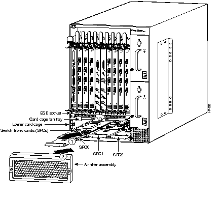
The switching fabric of the SFC is identical to that of the CSC. However, the SFCs do not perform any of the system services native to the CSC (see the section entitled "Clock and Scheduler Card" on page 34). The SFC merely augments the switching capacity of the router.
In the Cisco 12008, source AC or source DC power is converted by the installed power supply(ies) into the +5 VDC and -48 VDC required for router operation. These voltages are delivered to the backplane through the blind mating Elcon connector at the rear of the power supply enclosure. The backplane then distributes these operating voltages to all of the installed components in the system (see Figure 1-21).
The +5 VDC is fed to the MBus module on each installed card, and the -48 VDC is fed to a DC-DC converter on each card.
The DC-DC converter on each card operates under control of the card's MBus module. When directed by the GRP or system software during normal system startup, the DC-DC converter on each card is activated to convert the -48 VDC from the backplane into the voltages required to power the card's electronic circuitry.
The card cage fan tray and the power supply fan tray derive their operating power from a DC-DC converter on the CSC. This converter takes the -48 VDC from the backplane and converts it into the +24 VDC operating voltage required by the fan trays.
If an overtemperature condition is sensed anywhere within the router, or if any one of the fans fails in either the card cage fan tray or the power supply fan tray, the DC-DC converter on the CSC increases the voltage being delivered to the fan trays. This causes the fans to run at maximum speed to increase the volume of cooling air flowing through the router. Once the overtemperature condition is resolved, the fans revert to their normal operating speed.
Because the fans must operate continuously to prevent thermal damage to router components, they cannot be turned off by software.
Figure 1-21: Power Distribution System in the Cisco 12008
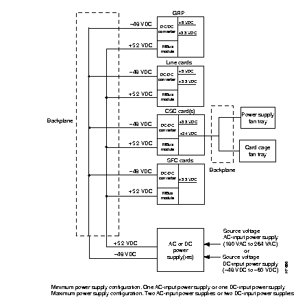
An environmental monitoring facility, called the maintenance bus (MBus), supports a variety of functions essential to router operations. These functions include the following:
- System discovery (enabling the router to identify installed components)
- Booting software images
- Supporting console traffic, logging functions, and diagnostic functions
- Monitoring the operational health of the router and reporting error conditions
The MBus facility in the router is interconnected by means of the backplane to the following components:
- GRP
- Line cards
- CSCs
- SFCs
- Power supplies
Each of the components listed here contains an onboard MBus module that incorporates two separate transceivers (A and B). Each transceiver has a separate etch (communication path) through the backplane. Consequently, all the MBus modules in the system are reliably interconnected to each other by means of redundant busses. This redundancy enhances the reliablity of the entire environmental monitoring system.
The MBus module on each component is powered by +5.2 VDC that it receives through the backplane from the power supply. A single MBus firmware image executes on all the MBus modules present in the system.
The master MBus module on the GRP monitors all the alarm conditions detected by the MBus modules in the other components of the system. The master MBus module then determines an appropriate response to the alarm condition.
The MBus modules on installed components perform the following functions:
- Power-up/down control--When power is applied to the router, the MBus module on the GRP and the CSC immediately receive +5.2 VDC through the backplane from the power supply, causing each card to supply power to its circuitry.
- The MBus modules on other installed components then power up on command from the master MBus agent on the GRP.
- A message is sent from the master GRP MBus agent, requesting that all installed components identify themselves. Each return response includes slot number, card type, and component type.
- Downloading software--A line card ROM monitor is loaded into Flash ROM on the card during the manufacturing process. This image, which can be field upgraded, if necessary, boots software to the line card by means of the MBus facility.
- Because the MBus is slow relative to the switch fabric, only enough code is initially downloaded to the line card to enable it to access the router's switch fabric.
- This initial code includes a line card fabric downloader that functions as a secondary bootstrap program to quickly complete the downloading of the Cisco IOS image to the line card by means of the router's high-speed switch fabric.
Table 1-6 lists the physical specifications of the Cisco 12008.
Table 1-7 outlines the electrical specifications of the AC-input power supply; Table 1-8 outlines similar specifications for the DC-input power supply.
Table 1-9 lists the environmental specifications of the Cisco 12008.
Table 1-6: Physical Specifications of the Cisco 12008
| Description
| Value
|
|---|
| Chassis height
| 24.8 inches (63.6 cm)
|
| Chassis width
| 17.4 inches (44.6 cm)
19.1 inches (48.5 cm), including mounting flanges
|
| Chassis depth
| 21.2 inches (54.4 cm), including cable- management system
|
| Weight, maximum configuration
| 180 lb (81.7 kg) with two DC-input power supplies
187 lb (84.9 kg) with two AC-input power supplies
|
| Weight, minimum configuration
| 127 lb (57.7 kg)
|
| Weight, shipping pallet
| 44 lb (20 kg)
|
| Weight, total system, on pallet
| 231 lb (104.9 kg)
|
| Weight, base chassis with backplane
| 50 lb (22.7 kg)
|
| Weight, card cage fan tray
| 12 lb (5.4 kg)
|
| Weight, power supply fan tray
| 2 lb (0.9 kg)
|
| Weight, AC-input power supply
| 17 lb (7.7 kg)
|
| Weight, DC-input power supply
| 14 lb (6.4 kg)
|
| Weight, line card
| 8 lb (3.6 kg)
|
| Weight, GRP
| 8 lb (3.6 kg)
|
| Weight, CSC
| 7 lb (3.2 kg)
|
| Weight, SFC
| 2 lb (0.9 kg)
|
Table 1-7: Electrical Specifications of the AC-Input Power Supply
| Power Supply
Type
| Electrical Characteristic
| Value
|
|---|
| AC
| Input power
| Maximum: 2000W
200 VAC to 240 VAC @ 10A
|
| AC
| Input voltage
| Nominal: 200 VAC to 240 VAC
Acceptable range: 180 VAC to 264 VAC, single phase
|
| AC
| Input current
| 9.5A @ 200 VAC
|
| AC
| Line frequency
| 47 to 63 Hz
|
| AC
| Output power
| Maximum: 1560W
-48 VDC @ 33.7A
+5 VDC @ 20.8A)
|
Table 1-8: Electrical Specifications of the DC-Input Power Supply
| Power Supply
Type
| Electrical Characteristic
| Value
|
|---|
| DC
| Input power
| Maximum: 1580W
-40.5 VDC to -75 VDC @ 39A to 21A
|
| DC
| Input voltage
| Nominal: -48 VDC (United States)
Acceptable range: -40.5 VDC to -56 VDC
Nominal: -60 VDC (International)
Acceptable range: -58 VDC to -75 VDC
|
| DC
| Input current
| 33.75A maximum @ -48 VDC
27A maximum @ -60 VDC
Internal circuit breaker is rated at 40A
|
| DC
| Output power
| Maximum: 1542W
-48 VDC @ 33.7A
+5 VDC @ 20.8A
|
Table 1-9: Environmental Specifications of the Cisco 12008
| Description
| Value
|
|---|
| Temperature
| Operating: 32° to 104° F (0° to 40° C)
Nonoperating: -4° to 149° F (-20° C to 65° C)
|
| Humidity
| Noncondensing, operating: 10 to 90%
Noncondensing, nonoperating: 5 to 95%
|
| Altitude
| Operating: 0 to 10,000 ft (0 to 3048 m)
Nonoperating: 0 to 30,000 ft (0 to 9144 m)
|
| Heat dissipation
| 6,000 Btu/hr maximum
|
| Acoustic Noise
| 69 dbA maximum
|
| Shock
| Operating: 5 to 500 Hz, 0.5 g1 (0.1 oct/min2)
Nonoperating: 5 to 100 Hz, 1 g (0.1 oct/min);
100 to 500 Hz, 1.5g (0.2 oct/min);
500 to 1000 Hz, 1.5 g (0.2 oct/min)
|
1
g = gravity.
2
oct/min = octave per minute.
In addition to meeting GR-63-CORE and GR-1089-CORE specifications, the Cisco 12008 meets the requirements of the agencies listed in Table 1-10.
Table 1-10: Agency Approvals
| Category
| Agency Approval
|
|---|
| Safety
| UL 1950
|
|
| CSA 22.2 No. 950
|
|
| EN60950
|
|
| AUSTEL TS001
|
|
| AS/NZS 3260
|
| EMI
| FCC Class A
|
|
| CSA Class A
|
|
| EN55022 Class A
|
|
| VCCI Class 2
|
|
| AS/NRZ 3548 Class A
|
| Immunity
| EN61000-4-2/IEC-1000-4-2
|
|
| EN61000-4-3/IEC-1000-4-3
|
|
| EN61000-4-4/IEC-1000-4-4
|
|
| EN61000-4-5/IEC-1000-4-5
|
|
| EN61000-4-6/IEC-1000-4-6
|
|
| EN61000-4-11/IEC-1000-4-11
|


