You might not have to configure the Catalyst 3900 for it to work in your network; it is shipped with default configuration parameters and can function with these defaults. However, if you want or need to alter the configuration of the Catalyst 3900, you can use a console session. This chapter provides information on the following:
To alter the configuration of your Catalyst 3900, follow these steps:
Step 1 If one has not already been established, establish a console session. For information about establishing a console session, refer to the "Planning for Configuration and Management" section.
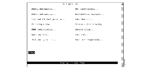
Step 2 At the Main Menu, select Configuration. The Configuration Menu (Figure 5-1) is displayed.
Figure 5-1: Configuration Menu Panel
Step 3 Select the menu option you want.
Step 4 Change or enter values according to the configuration parameters worksheets.
Step 5 When you have changed or entered all of the required configuration parameters, save the changes and return to the Main Menu. Configuration is complete.
As you move through the console panels, follow these guidelines:
- To select a menu or action item, move the cursor to the item and press Enter.
- To make changes to a parameter, move the cursor to the parameter name and press Enter. You will then be prompted to enter the new data or select from a list of valid choices.
- To make changes to a list entry, select Change and specify the entry identifier (index number). You will then be prompted to enter the new data or select from a list of valid choices. Some list entries consist of multiple parameters. To retain the current value of any parameter, enter a null value at the prompt.
- To save any changes made to the configuration panels in NVRAM, you must select Return. In most cases, changes will not take effect until you have exited the panel by selecting Return.
- To return to the main menu without saving your changes, press Ctrl-P. Changes made to the current panel will not be saved.
- To return to the previous panel without saving your changes, press the backspace key.
- To refresh the console panel at any time, press Ctrl-L.
- If the Catalyst 3900 is part of a stack, you will be prompted to select a box (Catalyst 3900) when you access certain configuration panels, such as the Switch/Stack Information panel.
- In some cases, more information is available than can be displayed on the panel. To scroll to the next panel of information, select More.
To view or change basic switch and stack information, such as the system name, system location, or system contact, select Switch Information on the Configuration Menu. The Switch Information panel (Figure 5-2) is displayed.
Figure 5-2: Switch Information Panel
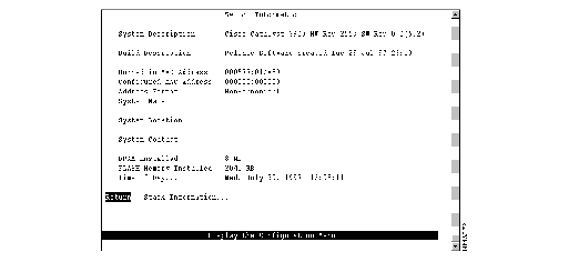
The following information is displayed on this panel:
- System Description--Full name and version identification of the system's hardware.
- Build Description--Version identification of the firmware.
- Burned-in MAC Address--Factory-assigned MAC address of the Catalyst 3900. Information in this field cannot be changed.
- Configured MAC Address--MAC address that is configured for the Catalyst 3900. If a locally administered address is assigned to the Catalyst 3900, this field displays that address. Otherwise, the field displays all 0s. To assign a locally administered address, select this field and enter the new address. The new address will take effect the next time the Catalyst 3900 is reset.
- Address Format--Format used for MAC addresses (non-canonical or canonical). Non-canonical is typically used in Token Ring networks and is also known as most significant bit first. The two parts of a non-canonical address are separated by a colon. Canonical format is typically used in Ethernet networks and is also known as least significant bit first. The two parts of a canonical address are separated by a dash. If you change the address format, the new format will be used for displaying addresses by all switches in the stack and will take effect immediately.
- System Name--Locally assigned name of this Catalyst 3900. This name will appear in SNMP traps.
- System Location--Location information for this Catalyst 3900. This location will appear in SNMP traps.
- System Contact--Name of system contact for this Catalyst 3900.
- DRAM Installed--Amount (in megabytes) of dynamic memory installed. Information in this field cannot be changed.
- FLASH Memory Installed--Amount (in kilobytes) of flash memory installed. Information in this field cannot be changed.
- Time of Day--Time according to the internal clock of the Catalyst 3900.
Note If this Catalyst 3900 is part of a stack, updates to the Address Format, System Name, System Location, and System Contact are propagated throughout the stack.
| To
| Select
| Then
|
|---|
| Change the current settings...
| The appropriate parameter...
| Specify the new value.
|
| View additional information about the switch...
| Stack Information
| Refer to the "Viewing Stack Information" section.
|
| Save your changes...
| Return
|
|
To view additional switch information, select Stack Information on the Switch/Stack Information panel. The Stack Information panel (Figure 5-3) is displayed.
Figure 5-3: Stack Information Panel
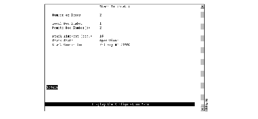
The following information is displayed on this panel:
- Number of Boxes--Number of Catalyst 3900 switches currently participating in the stack. Information in this field cannot be changed.
- Local Box Number--Number assigned to the Catalyst 3900 to which the console is connected. The local box is also the source of the information displayed on this panel. Information in this field cannot be changed.
- Remote Box Number(s)--Number of Catalyst 3900 switches (in addition to this one) in the stack. Information in this field cannot be changed.
- Stack Time-out (sec.)--If a switch goes off line, the length of time (in seconds) during which the stack tries to re-establish communication with the switch. The default is 16 seconds.
- Stack State--Indicates whether the ProStack is operational. Information in this field cannot be changed. Possible states are:
- Idle--The initial state.
- Discovery--The Catalyst 3900 is checking to see if a stack exists and, if so, what the values of the stack parameters are.
- Split Stack--A stack has been detected, but the parameters are different than those configured for this Catalyst 3900. To resolve a split stack, you must reset the Catalyst 3900 by pressing the System Request button.
- DP Update--Parameters for the stack are being updated.
- BI Update--The Catalyst 3900 is sending out information about it's configuration.
- VLAN BI Update--A port on the Catalyst 3900 has changed TrBRF assignments and the Catalyst 3900 is sending out updated configuration information.
- Operational--The stack has been formed successfully.
- Not Operational--The stack has not been formed. This may be because there is no stack port installed in the expansion slot or there is no connection between the stack port and any other Catalyst 3900 or Catalyst Matrix.
- Stack Connection--Indicates whether the ProStack is connected. Information in this field cannot be changed. Possible values are Not Connected, Not Present, or Primary WS-3900.
To view general information about the Catalyst 3900 and any expansion modules installed, select Module Information on the Configuration Menu. The Module Information panel (Figure 5-4) is displayed.
Figure 5-4: Module Information Panel
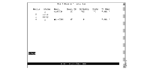
The following information is displayed on this panel:
- Module--Module number. The Catalyst 3900 is listed as module 1. Expansion modules are listed as module 2 and module 3. The stack port is listed as module 4.
- Status--Indicates whether the module is up, down, or the slot is empty.
- Model--Type of module. CAT3900 is listed for the base switch. For other modules, this field displays the product number.
- Board Id--Identifier of the board in decimal. For a list of possible board IDs, refer to the "Board IDs" section in the "Codes and IDs" appendix.
- Revision--Revision level of the module.
- Ports--Number of ports on the module.
- Up Time--Amount of time (in hours, minutes, and seconds) that the module has been up (since the last reset).
You cannot change the information that appears on this panel.
You can partition a single Catalyst 3900 into multiple VLANs. A VLAN can be configured with its own IP address and managed with SNMP. A VLAN can contain ports from multiple switches in the same stack. Any VLAN can participate independently in the Spanning-Tree Protocol. Once VLANs have been established, packets are forwarded between ports belonging to the same VLAN only.
You can use VTP to set up and manage VLANs across an entire administrative domain. When new VLANs are added to a Catalyst switch in an administrative domain, VTP can be used to automatically distribute the information to the trunk ports of all the devices in the management domain. This allows VLAN naming consistency and connectivity between all devices in the administrative domain.
For more information about Token Ring VLANs, refer to the "Token Ring VLANs" section of the "Understanding Token Ring Switching" appendix.
To configure VLANs and the VTP for the Catalyst 3900, select VLAN and VTP Configuration on the Configuration Menu. The VLAN and VTP Configuration panel (Figure 5-5) is displayed.
Figure 5-5: VLAN and VTP Configuration Panel
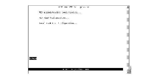
The following options are displayed on this panel:
- VTP Administrative Configuration--Select this option to display the current VTP parameters. Refer to the "Viewing VTP Parameters" section.
- VTP VLAN Configuration--Select this option to define VLANs. Refer to the "Configuring VLANs" section.
- Local VLAN Port Configuration--Select this option to display a list of the VLAN port assignments. Refer to the "Displaying VLAN Port Assignments" section.
To view parameters for the VTP, select VTP Administrative Configuration on the VLAN and VTP Configuration panel. The VTP Administrative Configuration panel (Figure 5-6) is displayed.
Figure 5-6: VTP Administrative Configuration Panel
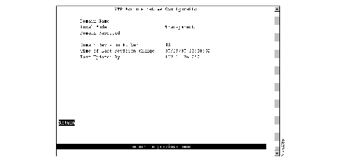
The following information is displayed on this panel:
- Domain Name--Name of the administrative domain the device is participating in (accepting updates from and propagating configuration changes to).
- Local Mode--VTP mode of the switch. Possible values are Server, Client, and Transparent. The default is Transparent.
- Server mode permits configuration changes from the local device. All devices in Server mode must be capable of storing configurations for all the VLANs in the administrative domain. The switch will not allow the user to configure VLANs in excess of 63. If this number is exceeded, the switch will automatically enter Client mode.
- Client mode accepts configuration changes only from other devices.
- Transparent mode passes along any VTP packets received. Transparent mode also accepts and stores changes to the local VLAN configuration database, but does not propagate the changes to other devices.
- Domain Password--Password of up to 64 characters common to all devices in the administrative domain. A configuration will not pass between two devices with different passwords even if they are configured with the same administrative domain name.
- Domain Revision Number--Revision number of the current configuration database implemented on this device.
- Time of Last Revision Change--Time the revision of the current configuration database implement on this device was created.
- Last Updated By--IP address of the server where the revision of the current configuration database implemented on this device was created.
You can define VLANs for the entire network from a single switch. The VLAN configuration is propagated to all switches in the same administrative domain using the VTP advertisement protocol. To define VLANs, select VTP VLAN Configuration on the VLAN and VTP Configuration panel. The VTP VLAN Configuration panel (Figure 5-7) is displayed.
Note This panel displays all VLANs in the administrative domain regardless of whether they are a VLAN type that is supported by the Catalyst 3900.
Figure 5-7: VTP VLAN Configuration Panel
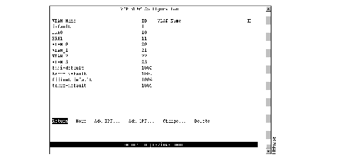
The following information is displayed on this panel:
- VLAN Name--ASCII name associated with the VLAN, which is synonymous with the VLAN's emulated LAN name on LANE trunks.
- ID--Numeric VTP ID, which is synonymous with the VLAN's ISL ID associated with the VLAN packets on ISL trunks.
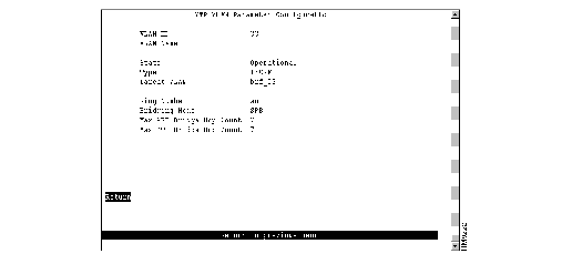
'To add a new TrBRF VLAN, select Add_BRF on the VLAN Configuration panel. To change the definition of an existing TrBRF VLAN, select Change on the VLAN Configuration panel and specify the VLAN ID. In either case, the VTP VLAN Parameter Configuration panel (Figure 5-8) is displayed.
Figure 5-8: VTP VLAN Parameter Configuration Panel
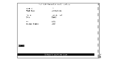
The following information is displayed on this panel:
- VLAN ID--Numeric VTP ID, which is synonymous with the VLAN's ISL ID associated with the VLANs packets on ISL trunks. Possible values are 1 through 1005.
- VLAN Name--ASCII name associated with the VLAN, which is synonymous with the VLAN's emulated LAN name on LANE trunks. Up to 32 characters are allowed.
- State--Current state of the VLAN. Possible values are Operational and Suspended. VLANs in operational state are functional. VLANs in suspended state do not pass packets. The default is Operational.
- Type--VLAN type.
- MTU--Maximum transmission unit of the VLAN. Possible values are 1500 through 18190. The default is 4472.
- Bridge Number-- Source-routing bridge number (in hexadecimal format) for this bridge. Possible values are 00 through 0F. The default is 0F.
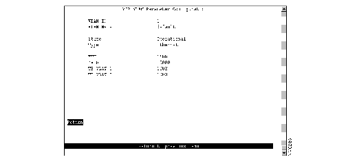
To add a new TrCRF VLAN, select Add_CRF on the VLAN Configuration panel. To change the definition of an existing TrCRF VLAN, select Change on the VLAN Configuration panel and specify the VLAN ID. In either case, the VTP VLAN Parameter Configuration panel (Figure 5-9) is displayed.
Figure 5-9: VTP VLAN Parameter Configuration Panel
The following information is displayed on this panel:
- VLAN ID--Numeric VTP ID, which is synonymous with the VLAN's ISL ID associated with the VLANs packets on ISL trunks. Possible values are 1 through 1005.
- VLAN Name--ASCII name associated with the VLAN, which is synonymous with the VLAN's emulated LAN name on LANE trunks. Up to 32 characters are allowed.
- State--Current state of the VLAN. Possible values are Operational and Suspended. VLANs in operational state are functional. VLANs in suspended state do not pass packets. The default is Operational.
- Type--VLAN type.
- Parent VLAN--TrBRF to which this VLAN belongs.
- Ring Number--Logical ring number (in hexadecimal format) assigned to this VLAN. Possible values are auto and 01 through FFF. The default is auto, meaning that the ring number will be learned. If the ring number has been learned, the ring number will be displayed in the format A-xxx.
 | Caution If the ports of the TrCRF VLAN are connected to a ring that contains only workstations, the port will be unable to learn the ring number. In this case, you must configure the ring number. |
- Bridging Mode--Bridging mode for this VLAN. Possible values are SRB and SRT. The default is SRB.
- Max ARE Bridge Hop Count--Maximum number of hops for all-routes explorer (ARE) frames. Possible values are 1 through 13. The default is 7.
- Max STE Bridge Hop Count--Maximum number of hops for spanning-tree explorer (STE) frames. Possible values are 1 through 13. The default is 7.
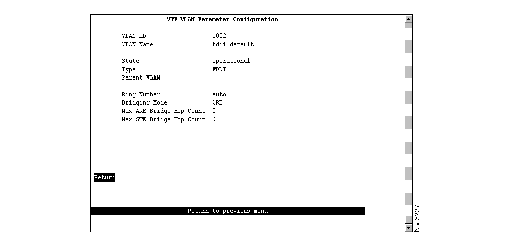
To change the definition of an existing Ethernet VLAN, select Change on the VLAN Configuration panel and specify the VLAN ID. The VTP VLAN Parameter Configuration panel (Figure 5-10) is displayed. You can change the values of the security association identifier and the translationally bridged VLANs only.
Figure 5-10: VTP VLAN Parameter Configuration Panel
The following information is displayed on this panel:
- VLAN ID--Numeric VTP ID, which is synonymous with the VLAN's ISL ID associated with the VLANs packets on ISL trunks.
- VLAN Name--ASCII name associated with the VLAN, which is synonymous with the VLAN's emulated LAN name on LANE trunks.
- State--Current state of the VLAN. Possible values are Operational and Suspended. VLANs in operational state are functional. VLANs in suspended state do not pass packets.
- Type--VLAN type.
- MTU--Maximum transmission unit of the VLAN.
- SAID--Security association identifier. Possible values are 1 through 2147483647. The default is 100100.
- TB VLAN 1--ID of a VLAN that is translationally bridged to this VLAN. Possible values are 0 through 1005.
- TB VLAN2--ID of a VLAN that is translationally bridged to this VLAN. Possible values are 0 through 1005.
To view the definition of an existing FDDI or FDDI-Net VLAN, select Change on the VLAN Configuration panel and specify the VLAN ID. The VTP VLAN Parameter Configuration panel (Figure 5-11) is displayed. You can view the definition of an FDDI or FDDI-Net VLAN, but cannot change it.
Figure 5-11: VTP VLAN Parameter Configuration Panel
The following information is displayed on this panel:
- VLAN ID--Numeric VTP ID, which is synonymous with the VLAN's ISL ID associated with the VLANs packets on ISL trunks. Possible values are 1 through 1005.
- VLAN Name--ASCII name associated with the VLAN, which is synonymous with the VLAN's emulated LAN name on LANE trunks. Up to 32 characters are allowed.
- State--Current state of the VLAN. Possible values are Operational and Suspended. VLANs in operational state are functional. VLANs in suspended state do not pass packets. The default is Operational.
- Type--VLAN type.
FDDI VLANs
If the VLAN type is FDDI, the following additional information is displayed for FDDI VLANs:
- Parent VLAN--FDDI-Net to which this VLAN belongs.
- Ring Number--Logical ring number (in hexadecimal format) assigned to this VLAN. Possible values are auto and 01 through FFF. The default is auto, meaning that the ring number will be learned. If the ring number has been learned, the ring number will be displayed in the format A-xxx.
- Bridging Mode--Bridging mode for this VLAN. Possible values are SRB and SRT. The default is SRB.
- Max ARE Bridge Hop Count--Maximum number of hops for all-routes explorer (ARE) frames. Possible values are 1 through 13. The default is 7.
- Max STE Bridge Hop Count--Maximum number of hops for spanning-tree explorer (STE) frames. Possible values are 1 through 13. The default is 7.
FDDI-Net VLANs
If the VLAN type is FDDI-Net, the following additional information is displayed for FDDI-Net VLANs:
- MTU--Maximum transmission unit of the VLAN. Possible values are 1500 through 18190.
- Bridge Number--Source-route bridging number (in hexadecimal format) for this bridge. Possible values are 00 through 0F.
To display a list of the VLAN port assignments, select Local VLAN Port Configuration on the VLAN and VTP Configuration panel. The Local VLAN Port Configuration panel (Figure 5-12) is displayed.
Figure 5-12: Local VLAN Port Configuration Panel
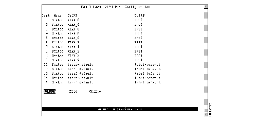
This panel displays the following information about the VLAN port assignments:
- Port--Port number.
- Mode--VLAN mode of the port. Possible values are Static and Trunk.
- TrCRF--TrCRF to which the port is currently assigned. By default, all ports are assigned to trcrf-default.
- TrBRF--Parent VLAN of the TrCRF to which the port is currently assigned. The default is trbrf-default.
| To
| Select
| Then
|
|---|
| Change the TrCRF to which the port is assigned...
| Change
| Select the VLAN from the displayed list of TrCRFs.
|
| Save your changes...
| Return
|
|
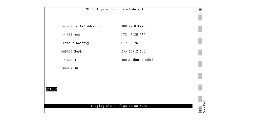
To view or change IP information associated with a TrBRF, such as the IP address, subnet mask, or IP state, or to send PINGs, select IP Configuration on the Configuration Menu and select the TrBRF from the list of TrBRFs. The IP Configuration panel (Figure 5-13) is displayed.
Figure 5-13: IP Configuration Panel
The following information is displayed on this panel:
- Interface MAC Address--MAC address of the switch.
- IP Address--Current IP address for the TrBRF. The default is 0.0.0.0.
- Default Gateway--Default gateway address. The default is 0.0.0.0.
- Subnet Mask--Current subnet mask. The default is 0.0.0.0.
- IP State--Current IP state. The default for the default TrBRF (trbrf-default) is "BootP When Needed." The default for all other TrBRFs is "IP Disabled."
- IP Disabled--Domain will not process any IP or Address Resolution Protocol (ARP) frames it receives. It will not respond to SNMP, PING, Telnet, or ARP frames that are received.
- BootP When Needed--If the IP address is zero (0.0.0.0), BootP requests will be broadcast by the Catalyst 3900 in an effort to learn its IP address. All other IP functions are disabled until it receives a reply. If a nonzero IP address has been configured (and stored in NVRAM), IP is enabled for the domain and will function immediately.
- BootP Always--IP is enabled for the domain, but will not function until a BOOTP reply is received. If a nonzero IP address for the domain is stored in NVRAM, it will be cleared to zero when the Catalyst 3900 is booted.
When you select either of the BootP options for the IP state, the Catalyst 3900 repeats BootP requests at regular intervals, beginning at 1 second intervals and eventually decreasing to 5 minute intervals until it has received a valid response.
The BootP response parameters that are recognized and recorded in NVRAM are:
- IP Address
- Default Gateway
- Subnet Mask
- TFTP Bootfile Name
- TFTP Server Address
The BootP requests will also cease if a valid IP address is configured via the console panels or if the IP state is set to IP Disabled. Once the Catalyst 3900 stops sending BootP requests on a domain, it does not resume sending requests or recognize BootP responses on that domain unless the Catalyst 3900 is reset.
For more information about BootP, refer to the appendix "Understanding BootP."
| To
| Select
| Then
|
|---|
| Change the current settings...
| The appropriate parameter...
| Specify the value.
|
| Verify the network availability of a particular resource...
| Send PING
| Specify the IP address of the resource.
|
| Save your changes...
| Return
|
|
Note IP addresses are always entered in dotted-decimal notation (a set of 4 decimal numbers from 0 through 255 separated by periods). The default is 0.0.0.0. If the default is used, no SNMP management will be available until the switch learns its address.
To allow the Catalyst 3900 to be managed by an SNMP manager, you must first configure the SNMP parameters. To view or set SNMP parameters, such as the community names, where traps are to be sent, and whether authentication failure traps should be sent, select SNMP Configuration on the Configuration Menu. The SNMP Configuration panel (Figure 5-14) is displayed.
Figure 5-14: SNMP Configuration Panel
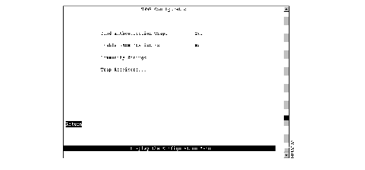
The following information is displayed on this panel:
- Send Authentication Traps--Indicates whether an authentication trap should be issued to Trap Receivers whenever authentication of an SNMP request fails. Traps indicating cold and warm boots are always sent. Possible values are Yes and No. The default is Yes.
- Enable RMON statistics--Enables the gathering of a subset of the RMON statistics from the RMON MIB (if you have requested the RMON option). Possible values are Yes and No. Changes to this field are effective after the switch is reset. The default is No. The statistics collected are:
- Token Ring Statistics
- History
- Events
- Alarms
|
To
| Select
| Then
|
|---|
| Change the current settings...
| The appropriate parameter...
| Specify the value.
|
| View or change SNMP community names and privileges...
| Community Strings
| Refer to the "Specifying Community Names" section.
|
| View or change which SNMP managers are to receive traps for which domains...
| Trap Receivers
| Refer to the "Specifying Trap Receivers" section.
|
| Save your changes...
| Return
|
|
A community name is a password that a set of SNMP managers use to manage a specified device. Each community name is associated with a specific privilege level of management. To view or change the community names for the domains of the Catalyst 3900, select Community Strings on the SNMP Configuration panel. The Community Strings panel (Figure 5-15) is displayed.
Figure 5-15: Community Strings Panel
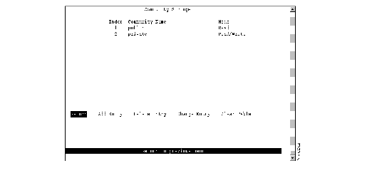
The following information is displayed on this panel:
- Index--Identifier of the community name entry.
- Community Name--Name, or password, used to identify the SNMP managers.
- Mode--The privilege level assigned to this name. Read specifies that SNMP managers can only view SNMP information. Read/Write specifies that SNMP managers can both view and change SNMP information.
Entries are displayed in the order in which they are entered. Only five community names can be entered.
| To
| Select
| Then
|
|---|
| Add a community name...
| Add Entry
| Specify the community name and privilege.
|
| Delete a community name...
| Delete Entry
| Specify the name to be deleted.
|
| Change a community name or privilege...
| Change Entry
| Specify the index number of the entry to be changed and enter the new information.
|
| Delete all community names...
| Clear Table
|
|
| Save your changes...
| Return
|
|
To view or change the list of SNMP managers to which traps are sent, select Trap Receivers on the SNMP Configuration panel. The Trap Receivers panel (Figure 5-16) is displayed.
Figure 5-16: Trap Receivers Panel
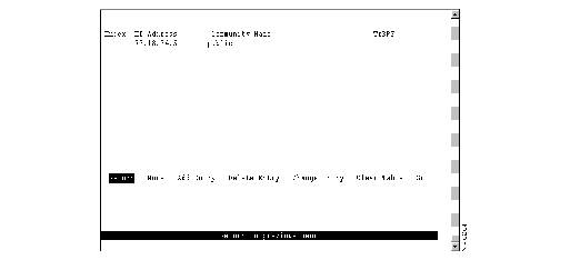
The following information is displayed on this panel:
- Index--Identifier of the trap receivers entry.
- IP Address--IP address of the SNMP manager.
- Community Name--Name used to identify the SNMP managers.
- TrBRF--VLANs for which traps are sent to the specified SNMP manager.
The trap receivers list can contain a maximum of six entries.
| To
| Select
| Then
|
|---|
| Add an entry to the list...
| Add Entry
| Specify the IP address, community name, and domain.
|
| Delete an entry...
| Delete Entry
| Specify the index number of the entry to be deleted.
|
| Change an entry in the list...
| Change Entry
| Specify the index number of the entry to be changed and enter the new information.
|
| Delete all entries...
| Clear Table
|
|
| Display the complete list of TrBRFs assigned to an IP address...
| Zoom
| Specify the index number.
|
| Save your changes...
| Return
|
|
Enabling the Catalyst 3900 to participate in a spanning tree allows you to configure redundant (backup) paths in the switch topology and have the switch automatically disable redundant paths to prevent loops. If an active path is broken and a backup path is available, the switch will locate the redundant path and enable it. Without a spanning tree, a path failure means the loss of connectivity for the affected part of the network.
For more information about spanning tree, refer to the "Spanning-Tree Protocol" section of the "Understanding Token Ring Switching" appendix.
To view or change the spanning-tree parameters associated with a VLAN, such as the switch priority and the port path cost, select Spanning Tree on the Configuration Menu and then select the desired TrBRF. The Spanning Tree for TrBRF panel (Figure 5-17) is displayed.
Figure 5-17: Spanning Tree for TrBRF Panel
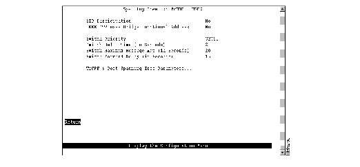
The following information is displayed on this panel:
- STP Participation--Indicates whether this TrBRF participates in the Spanning-Tree Protocol and, if so, the protocol to be used. Possible values are no, IEEE, IBM, and base on bridging mode. The default is no.
- If STP participation is set to no, then all TrCRFs with this TrBRF as a parent will be set to forwarding mode.
- If STP participation is set to IEEE or IBM, then the selected protocol will be used to determine the forwarding/blocked mode of the TrCRFs that are configured with an STP mode of auto.
- If STP participation is set to base on bridging mode, then the Spanning-Tree Protocol used is based on the bridging mode of the TrCRF. If the bridging mode is SRB, the IBM Spanning-Tree Protocol is used. If the bridging mode is SRT, the IEEE 802.1d Spanning-Tree Protocol is used.
- IEEE STP uses Bridge Functional Address--Indicates whether to use the bridge functional address instead of the IEEE Spanning Tree Protocol address when the TrBRF is configured to use the IEEE Spanning Tree Protocol.
- Switch Priority--Priority value for this Catalyst 3900 (0 through 65535). The lower the priority value, the higher the priority. The bridge or switch with the lowest priority value in a spanning tree becomes the root. The default is 32768.
- Switch Hello Time (in Seconds)--Time the Catalyst 3900 waits before sending the next configuration message when this Catalyst 3900 is the root switch. The minimum value is 1. The maximum value is the lower of 10 or (Switch Maximum Message Age ³ 2) - 1. The default is 2.
- The valid range for this parameter is displayed when you select Switch Hello Time.
- Switch Maximum Message Age (in Seconds)--Maximum message age used when this Catalyst 3900 is the root switch. This parameter sets the time at which the configuration message used by the spanning-tree algorithm should be discarded. The minimum value is the higher of 6 or 2 x (Switch Hello Time + 1). The default is 20.
- The maximum cannot be more than the lower of 40 or 2 x (Switch Forward Delay - 1).
- The range limits that appear when you select this parameter are calculated using the values currently selected for Switch Hello Time and Switch Forward Delay.
- Switch Forward Delay (in Seconds)--Time the Catalyst 3900 waits between transitions from listening to learning and from learning to forwarding. The minimum is the larger of 4 or (Switch Maximum Message Age ³ 2) + 1. The default is 15. The maximum is 30.
- The lower range limit that appears when you select this parameter reflects the value currently selected for Switch Maximum Age.
|
To
| Select
| Then
|
|---|
| Change the current settings...
| The appropriate parameter...
| Specify the value.
|
| View or change the spanning-tree parameters for one of the TrCRFs associated with this TrBRF...
| TrCRF & Port Spanning Tree Parameters
| Refer to the "Changing Spanning-Tree Parameters for a TrCRF" section.
|
| Save your changes...
| Return
|
|
To view or change the spanning-tree parameters for a TrCRF associated with the selected TrBRF, select TrCRF & Port Spanning Tree Parameters on the Spanning Tree panel and then select the desired TrCRF. The Spanning Tree for TrCRF panel (Figure 5-18) is displayed.
Figure 5-18: Spanning Tree for TrCRF Panel
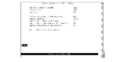
The following information is displayed on this panel:
- STP Mode (TrBRF to TrCRF)--Determines the mode of the link from this TrCRF to its TrBRF. Possible values are auto, forwarding, and blocked. If the parent TrBRF is participating in spanning tree, then auto is the default. If the TrBRF is not participating in spanning tree, then forwarding is the default.
- STP Priority--Priority associated with the TrCRF. The VLAN with the lowest priority value has the highest priority and will forward the spanning-tree frames. The possible range is 0 through 255 (decimal). The default is 128. If all VLANs have the same priority value, the lowest VLAN ID forwards the spanning-tree frames.
- STP Cost--Cost associated with the TrCRF. The Spanning-Tree Protocol uses path costs to determine which VLAN to select as a forwarding VLAN. Therefore, lower numbers should be assigned to VLANs that use faster media (such as FDX or TokenChannel), and higher numbers should be assigned to VLANs that use slower media. The possible range is 1 to 65535. The default is 62. A rule of thumb for the path cost is 1000 ³ LAN speed in megabits per second.
- STP Participation (TrCRF to ports)--Whether this TrCRF participates in the Spanning-Tree Protocol and, if so, the protocol to be used. Possible values are no, IEEE, and Cisco. The default is no. The Cisco Spanning-Tree Protocol is based on IEEE 802.1d, however, the bridge protocol data unit (BPDU) messages are sent to a different functional address.
- If STP Participation is set to no, then all ports belonging to this TrCRF will be set to forwarding mode.
- If STP Participation is set to IEEE or Cisco, then the selected protocol will be used to determine the forwarding/blocking mode of the ports that are configured with an Spanning-Tree Protocol mode of auto.
- Switch Priority--Priority associated with this Catalyst 3900 (0 through 65535). The lower the priority value, the higher the priority. The bridge or switch with the lowest priority value in a spanning tree becomes the root. The default is 32768. To change individual port properties, select Port Spanning Tree Parameters.
- Switch Hello Time (in Seconds)--Time the Catalyst 3900 waits before sending the next configuration message when this Catalyst 3900 is the root switch. The minimum value is 1. The maximum value is the lower of 10 or (Switch Maximum Message Age ³ 2) - 1. The default is 2.
- The valid range for this parameter is displayed when you select Switch Hello Time.
- Switch Maximum Message Age (in Seconds)--Maximum message age used when this Catalyst 3900 is the root switch. This parameter sets the time at which the configuration message used by the spanning-tree algorithm should be discarded. The minimum value is the higher of 6 or 2 x (Switch Hello Time + 1). The default is 20.
- The maximum cannot be more than the lower of 40 or 2 x (Switch Forward Delay - 1).
- The range limits that appear when you select this parameter are calculated using the values currently selected for Switch Hello Time and Switch Forward Delay.
- Switch Forward Delay (in Seconds)--Time the Catalyst 3900 waits between transitions from listening to learning and from learning to forwarding. The minimum is the larger of 4 or (Switch Maximum Message Age ³ 2) + 1. The default is 15. The maximum is 30.
- The lower range limit that appears when you select this parameter reflects the value currently selected for Switch Maximum Age.
|
To
| Select
| Then
|
|---|
| Change the current settings...
| The appropriate parameter...
| Specify the value.
|
| View or change the spanning-tree parameters for the ports that belong to this TrCRF...
| Port Spanning Tree Parameters
| Refer to the "Changing Spanning-Tree Parameters for a Port" section.
|
| Save your changes...
| Return
|
|
To view or change the priority, path cost, and spanning-tree mode of a port, select Port Spanning Tree Parameters on the Spanning Tree panel. The Port Spanning Tree Parameters panel (Figure 5-19) is displayed.
Figure 5-19: Port Spanning Tree Parameters Panel
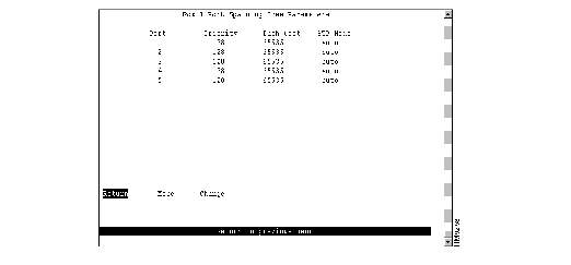
The following information is displayed on this panel:
- Port--Identifier of the port.
- Priority--Priority associated with the port. The port with the lowest priority value has the highest priority and will forward the spanning-tree frames. The possible range is 0 through 255 (decimal). The default is 128. If all ports have the same priority value, the lowest port number forwards the spanning-tree frames.
- Path Cost--Cost associated with the port. The Spanning-Tree Protocol uses port path costs to determine which port to select as a forwarding port. Therefore, lower numbers should be assigned to ports attached to faster media (such as FDX or TokenChannel), and higher numbers should be assigned to ports attached to slower media. The possible range is 1 to 65535. The default is 62. A rule of thumb for path cost is 1000 ³ LAN speed in megabits per second.
- STP Mode--Port's spanning-tree mode. Possible values are forwarding, blocked, and auto. If the TrCRF to which the port belongs is participating in the spanning tree (Cisco or IEEE), then auto is the default and the selected protocol will be used to determine whether the port is forwarding or blocked. If the TrCRF to which the port belongs is not participating in the spanning tree, then forwarding is the default.
|
To
| Select
| Then
|
|---|
| Change a parameter associated with a port...
| Change
| Specify the port number, select the appropriate parameter, and then specify the new value.
|
| Save your changes...
| Return
|
|
To view or change the configuration parameters of a port such as the mode, type, and speed, select Port Configuration on the Configuration Menu and specify the port number. The Port Configuration panel (Figure 5-20) is displayed.
Figure 5-20: Port Configuration Panel
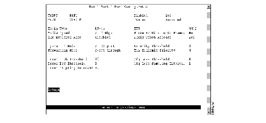
The following information is displayed on this panel:
- TrBRF--TrBRF that is the parent of the TrCRF to which the port is assigned.
- TrCRF--TrCRF to which this port is assigned.
- Enabled--Indicates whether the port is currently enabled. Possible values are Yes (to enable) and No (to disable). The default is Yes.
- Status--Current status of the port. Possible values are Inserted, Not Inserted, Wire Fault, Lobe Test Fail, HDX Frame Error, Heart Beat Fail, FDX New Station, FDX Prot Error, Speed Error, Remove Received.
- Media Type--Media type as determined by the module to which the port belongs. Possible values are RJ-45 and ST Fiber.
- Media Speed--Token Ring media speed. Possible values are 4 Mbps, 16 Mbps, and auto. The default is auto.
Note A port configured with a media speed of auto will not insert into an empty ring as the port will be unable to determine the media speed.
- Max Explorer Rate--Maximum explorer frame-forwarding rate (in frames per second). Possible values are 0 through 5000 and disabled. The default is disabled. If you set this parameter to 0, no explorers are forwarded. To change the value from a numeric value to disabled, select the field and enter a null value when prompted.
- MTU--Maximum transmission unit. Possible values are 1500 and 4472. The default is 4472.
- Force AC Bits on SR Frames--Indicates whether the address recognized (A) bit and the frame copied (C) bit should be set unconditionally on repeated source-routed LLC frames. These include source-routed frames with RIF length greater than 2 and all spanning-tree explorer and all-routes explorer frames. The default is no. If this parameter is set to no, the setting of these bits is based on whether the frame was actually forwarded.
- Early Token Release--Indicates whether the port is enabled for Early Token Release. Possible values are Yes and No. The default is Yes. Early Token Release is valid for 16 Mbps media only. If the Early Token Release is set to Yes and the media speed is 4 Mbps, the switch will force Early Token Release to No.
- Operation Mode--Port operation mode. Possible values are auto, HDX port, HDX station, FDX port, FDX station, RI/RO, and passive. The default is auto. Only HDX and FDX modes can be automatically detected. The operation mode of RI/RO can be set for ports 19 and 20 only.
Note Passive mode is displayed if the port has been selected as a passive monitoring port. You cannot specify an operation mode of passive nor can you change the operation mode of a passive port on this panel. To change the operation mode of a passive monitoring port, you must first remove the port from passive mode using the Switched Port Analyzer panel. For more information, refer to the "Monitoring Port Traffic" section.
- Forwarding Mode--Forwarding mode that will be used to transmit frames. Possible values are auto, cut through, and store & forward. The default is auto. If the forwarding mode is set to auto, the actual mode will depend on the number of errors that occur during the sampling interval. If the error rate is below the error low threshold, then cut-through mode is used. If the error rate is above the error high threshold, then store & forward is used. Store & forward mode is always used for ports with a media speed of 4 Mbps.
- Priority Threshold--Highest Token Ring frame priority in the Frame Control field of the frame that the switch should place in the low-priority transmit queue. Possible values are 0 through 7. The default is 3.
- Min Transmit Priority--Minimum reservation priority used when requesting a token on a busy ring. Possible values are 0 through 6. The default is 4.
- Error High Threshold--Value (in percentage) used to force a port to store & forward mode. When the percentage of errors detected in the error sampling interval is more than the error high threshold, then the port is forced to store-and-forward mode. Possible values are 0 through 100. The default is 10. This field is valid only when the forwarding mode is set to auto.
- Error Low Threshold--Value (in percentage) used to return a port to cut-through mode. When the percentage of errors detected in the error sampling interval is less than the error low threshold, then the port is allowed to return to cut-through mode. Possible values are 0 through 100. The default is 1. This field is valid only when the forwarding mode is set to auto.
- Error Sampling Interval--Sampling period (in minutes) used when counting errors to determine a port's forwarding mode. Possible values are 1 through 60. The default is 10. This field is valid only when the forwarding mode is set to auto.
- Cfg Loss Threshold--Value used to control the number of configuration losses that can occur within the configuration loss sampling interval. Configuration loss occurs when a port completes a connection, allows data traffic to flow, and subsequently closes. When the threshold is exceeded, the port is disabled and must be enabled via this panel or an SNMP manager. Possible values are 1 through 100. The default is 8.
- Cfg Loss Sampling Interval--Sampling period (in minutes) used when measuring the number of configuration losses occurring. Possible values are 1 through 60. The default is 1.
Note If you change any configuration parameters of a connected port, the port will close and reopen and you will lose all address information and statistics for that port.
| To
| Select
| Then
|
|---|
| Change the current settings...
| The appropriate parameter...
| Specify the new value.
|
| Save your changes...
| Return
|
|
The CDP is used with Cisco IOS software to establish communication between different models of Cisco equipment (such as between a Cisco Catalyst 3900 switch and a Cisco 7000 router).
Each device configured for CDP sends periodic messages to a multicast address. Each device advertises at least one address at which it can receive SNMP messages. The advertisements also contain time-to-live, or holdtime, information, which indicates the length of time a receiving device should hold CDP information before discarding it.
To configure CDP parameters, select CDP Configuration on the Configuration Menu. The CDP Configuration panel (Figure 5-21) is displayed.
Figure 5-21: CDP Configuration Panel
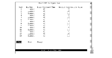
The following information is displayed on this panel:
- Port--Identifier of the port.
- Ena/Dis--Indicates whether CDP is enabled for the port. The default is Enabled.
- Trans Frequency Time--Time (in seconds) between CDP messages. The default is 60.
- Default time-to-live value--Time (in seconds) that a receiving device should hold a CDP packet from your switch before discarding it. The CDP hold time must be set to a greater number of seconds than the time between CDP transmissions (the transmission frequency time). The default is 180.
|
To
| Select
| Then
|
|---|
| Change a parameter associated with a port...
| Change
| Specify the port number, select the appropriate parameter, and then specify the new value.
|
| Save your changes...
| Return
|
|
The Catalyst 3900 allows you to configure a Switched Port Analyzer (SPAN) port for monitoring port traffic. This SPAN support allows you to monitor traffic on any of the Token Ring ports. You can define both active and passive monitors.
An active port monitor allows you to monitor traffic using a customer-supplied monitoring device, such as an RMON probe, or a trace tool, such as a Network General Sniffer. The trace tool monitors only the LLC traffic that is switched by the monitored port. The MAC frames are not monitored.
A passive port monitor allows you to monitor all the frames on a particular ring, including the MAC frames. You can configure two passive port monitors. Each passive port monitor can monitor traffic in only one direction at a time. Therefore, if the port you want to monitor is operating in FDX mode, you must configure both passive port monitors to monitor the same port. Otherwise, you can use the two passive port monitors to monitor two ports that are operating HDX mode.
To configure a SPAN port, select Switched Port Analyzer on the Configuration Menu. The Switched Port Analyzer panel (Figure 5-22) is displayed.
Figure 5-22: Switched Port Analyzer Panel
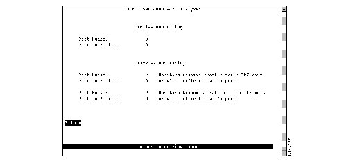
The following information is displayed on this panel:
- Port Number--Port to which the network analyzer or RMON probe will be attached. Possible values are 0 through 28.
- Port To Monitor--Port that will be monitored. Possible values are 0 through 28.
|
To
| Select
| Then
|
|---|
| Change the current settings...
| The appropriate parameter...
| Specify the value.
|
| Disable the SPAN port...
| Port to Monitor
| Specify 0.
|
| Save your changes...
| Return
|
|
To view or change the TokenChannel definitions, select TokenChannel on the Configuration Menu. The TokenChannel panel (Figure 5-23) is displayed.
Figure 5-23: TokenChannel Panel
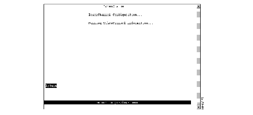
The following options are displayed on this panel:
To configure one or more TokenChannels, select TokenChannel Configuration on the TokenChannel panel. The TokenChannel Configuration panel (Figure 5-24) is displayed.
A single TokenChannel can consist of a combination of HDX and FDX connections. For example, a TokenChannel consisting of three connections can have one HDX and two FDX connections. However, both ports in each interconnected pair must be either HDX or FDX. In addition, all ports in a single TokenChannel must belong to the same TrCRF on the Catalyst 3900.
 | Caution You cannot use TokenChannels to interconnect different models of switches. For example, you cannot use a TokenChannel to interconnect a Catalyst 2600 and a Catalyst 3900. Likewise, you cannot use a TokenChannel to interconnect a Catalyst 3900 and a non-Cisco switch. |
Figure 5-24: TokenChannel Configuration Panel
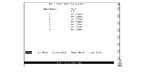
The following information is displayed on this panel:
- TokenChannel--Identifier of the TokenChannel (1 through 8).
- Ports--List of ports assigned to this TokenChannel.
You must define the TokenChannels for both connected Catalyst 3900s before physically connecting the linked ports. Therefore, make sure that you have either disabled the ports or disconnected the cables before you configure the TokenChannel. Otherwise, you will create loops.
Note When you physically connect the linked ports, make sure that the ports with the lowest port numbers are connected. For example, if a TokenChannel links ports 3, 6, and 7 of one Catalyst 3900 and ports 2, 4, and 5 of another Catalyst 3900, the ports must be connected to each other in the following manner: port 3 to port 2, port 6 to port 4, and port 7 to port 5.
| To
| Select
| Then
|
|---|
| Define a new TokenChannel...
| Add Entry
| Specify the ports that compose the new TokenChannel. The port numbers must be entered from lowest to highest and be separated by spaces. You cannot specify more than 8 ports.
|
| Delete the definition for a TokenChannel...
| Delete Entry
| Specify the identifier of the TokenChannel to be deleted.
|
| Change the definition of a TokenChannel...
| Change Entry
| Specify the identifier of the TokenChannel to be changed and enter the new information. The ports associated with a TokenChannel must be disabled or disconnected before you change the TokenChannel definition.
|
| Delete all TokenChannel definitions...
| Clear Table
| Confirm the deletion of all TokenChannel definitions.
|
| Save your changes...
| Return
|
|
To view the configuration of currently defined TokenChannels, select Running TokenChannel Information on the TokenChannel panel. The Running TokenChannel Information panel (Figure 5-25) is displayed.
Figure 5-25: Running TokenChannel Information Panel
The following information is displayed on this panel:
- TokenChannel--Identifier of the TokenChannel.
- State--Indicates whether the TokenChannel is up or down.
- Ports--List of ports assigned to this TokenChannel.
 | Caution If one of the links in a TokenChannel goes down, the whole TokenChannel will become inoperative. |
For network security, you can isolate parts of your network by limiting the scope and access of your users. For example, you might want to limit access to a specific file server to a select group of users. To limit access, you can do the following:
- Attach the printer to a single port on the Catalyst 3900.
- Create a filter that blocks all data to a port except that which is explicitly allowed (using Port Security).
- Define a filter that explicitly allows data from the select group of users (based on MAC address) to be sent to that port (using MAC Filters).
To limit the scope and access of users on segments attached to the Catalyst 3900, select Filters & Port Security from the Configuration Menu. The Filters & Port Security panel (Figure 5-26) is displayed.
Figure 5-26: Filters & Port Security Panel
The following options are displayed on this panel:
- Configure Filters--Select this option to configure MAC address filters. For more information, refer to the "Filtering Data Based on MAC Address" section.
- Configure Port Security Mode--Select this option to block communication at selected ports. For more information, refer to the "Securing Ports" section.
- View Port Filters--Select this option to view the currently defined filters. For more information, refer to the "Viewing Filters for a Specific Port" section.
- Protocol Filters--Select this option to configure protocol filters. For more information, refer to the "Filtering Data Based on Protocol" section.
To restrict certain users from communicating with other users or resources (such as printers or servers), select Configure Filters on the Filters & Port Security panel. The Configure Filters panel (Figure 5-27) is displayed.
Figure 5-27: Configure Filters Panel
The following information is displayed on this panel:
- Index--Identifier of the filter.
- MAC Address--MAC address contained in packets to be filtered.
- Type--Possible types are:
- block src--Block any packet with source address.
- block dest--Block any packet with destination address.
- allow src--Allow any packet with source address.
- allow dest--Allow any packet with destination address.
- allow lma--Allow any packet with limited multicast address to port(s).
- force dest--Force any packet with the designated destination address to port.
- Applied Ports--Input port where the filtering takes place. You specify applied ports for all filters.
- Exit Ports--Port, if any, that is to receive the filtered packets. This applies only to filters defined as "Allow any packet with the designated Source address to port(s)" or "Force any packet with the designated Destination Address to port(s)."
You can define up to 250 source or destination MAC addresses to be filtered at the port of entry into the Catalyst 3900. MAC addresses can be unicast, multicast (group), or broadcast. All 250 addresses can be associated with one port or divided among the available ports.
| To
| Select
| Then
|
|---|
| Display the complete list of Entry Ports and Exit Ports for a filter...
| Zoom
| Specify the index number.
|
| Add a filter...
| Add Entry
| Specify the filter type, the MAC address, and the ports. The port numbers should be listed from lowest to highest and be separated by spaces. If you do not specify a port number, the filter will be applied to all ports.
|
| Delete a filter...
| Delete Entry
| Specify the index number of the filter to be deleted.
|
| Delete all filters...
| Clear Table
| Confirm the deletion of all filters.
|
| Save your changes...
| Return
|
|
Note If you set up a filter for broadcast packets, hosts on the other side of the Catalyst 3900 will not see the ARP broadcast packets. To prevent this, allow time for the Catalyst 3900 to learn the host addresses before implementing the filter.
Note If you are defining a filter for a TokenChannel, the filter must be defined for all ports in the TokenChannel.
The Catalyst 3900 also allows you to totally block (secure) communication at selected ports, unless explicitly allowed by a MAC filter. Addresses that have been allowed or forced by a configured filter are not blocked. To define the security attributes of each port, select Configure Port Security Mode on the Filters & Port Security panel. The Configure Port Security Mode panel (Figure 5-28) is displayed.
Figure 5-28: Configure Port Security Mode Panel
The following information is displayed on this panel:
- Port--Identifier of the port.
- Security Mode--Level of security defined for that port. Possible values include:
- Normal--No security mode is defined for a port. This mode is the default.
- Secure source addresses--Block all source addresses, except those allowed by a configured filter.
- Secure destination addresses--Block all destination addresses, except those forced by a configured filter.
- Secure both source and destination addresses--Block all source and destination addresses, except those allowed or forced by a configured filter.
|
To
| Select
| Then
|
|---|
| Change the security mode for a port...
| Change
| Specify the port and the desired security mode.
|
| Save your changes...
| Return
|
|
To display the defined filters for a specific port, select View Port Filters on the Filters & Port Security panel and specify the port number. The View Port Filters panel (Figure 5-29) is displayed.
Figure 5-29: View Port Filters Panel
The following information is displayed on this panel:
- Index--Identifier of the filter entry.
- MAC Address--MAC address contained in the packets to be filtered.
- Description--Filter action to take on the packet with the specified MAC address.
You cannot change any information on this panel.
To filter data based on protocol, you can define protocol classes and then assign filtering attributes to these classes on a per-port basis. In protocol filtering, each incoming frame is assigned to one of the protocol classes based on the DSAP or Ethertype of the frame. If the DSAP is 0xAA (which indicates SNAP), the assignment is based on the Ethertype of the SNAP header. The mapping from DSAP or Ethertype to protocol class is common for all switch ports in a stack.
To filter data based on protocol, select Protocol Filters on the Filters & Port Security panel. The Protocol Filters panel (Figure 5-30) is displayed.
Figure 5-30: Protocol Filters Panel
The following options are displayed on this panel:
To use protocol filtering, you must first define the protocol classes. You can define up to 15 protocol classes for use in protocol filtering. To define the protocol classes, select Protocol Class Assignment on the Protocol Filters panel. The Protocol Class Assignment panel (Figure 5-31) is displayed.
Figure 5-31: Protocol Class Assignment Panel

The following information is displayed on this panel:
- Class--Identifier of the protocol class. By default, the names are 01 through 15. You can select a class and assign a new name.
- Ethertype--List of the Ethernet protocol types that you want to filter. You can specify a single Ethertype (in its 4-digit hexadecimal format). You cannot specify an Ethertype for protocol classes 9 through 15. For a list of possible Ethertypes, refer to the "Ethertypes" section of the "Codes and IDs" appendix.
- DSAPs--List of the DSAPs that you want to filter. You can specify up to 16 DSAPs (in hexadecimal format) separated by spaces. For a list of possible service access points (SAPs), refer to the "Service Access Points" section of the "Codes and IDs" appendix.
Note All DSAPs that are not specifically assigned to a protocol class are assigned to class 0.
| To
| Select
| Then
|
|---|
| Change the current settings...
| The appropriate port...
| Specify the value.
|
| Save your changes...
| Return
|
|
After you have defined your protocol classes, you can define how a port handles frames for each protocol class. To define how each class is handled, select Port Filtering Attributes on the Protocol Filters panel and specify the port number. The Port Filtering Attributes panel (Figure 5-32) is displayed.
Figure 5-32: Filtering Attributes for a Port Panel
The following information is displayed on this panel:
- Class--Identifier of the class.
- Block--How the port handles frames that fall into this protocol class. Possible values are:
- All--Block all frames in this protocol class.
- SR--Block all source-routed frames in this protocol class.
- NSR--Block all non-source-routed frames in this protocol class.
- None--Allow all frames in this protocol class.
- The default is None.
- SRT--Indicates whether the port allows transparent bridging of frames in this protocol class.
- Ethertype--Ethertypes defined for this class.
- DSAPs--DSAPs defined for this class.
Note For protocol class 0, Block is set to None and SRT is set to Yes.
| To
| Select
| Then
|
|---|
| Change the current settings...
| The appropriate parameter...
| Specify the value.
|
| Save your changes...
| Return
|
|
To ensure that the address tables (per port and master) are kept to a minimum size, you can configure an aging limit. The aging limit is used to determine when inactive MAC addresses are removed from the address table. To define address table aging limits, select Address Aging from the Configuration Menu. The Address Aging panel (Figure 5-33) is displayed.
Figure 5-33: Address Aging Panel
The following options are displayed on this panel:
Note To completely disable address aging, you must disable address aging for the ports and the master address table.
To define the address aging limits of each port, select Port Address Table Aging on the Address Aging panel. The Port Address Table Aging panel (Figure 5-34) is displayed.
Figure 5-34: Port Address Table Aging Panel
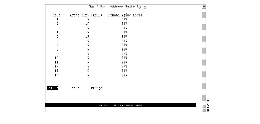
The following information is displayed on this panel:
- Port--Identifier of the port.
- Aging Time (min.)--Time (in minutes) an inactive MAC address will remain in the port's address table. Possible values are 0 through 9999 minutes. The default is 5 minutes. Zero indicates that address aging is disabled.
- Demand Aging Level--Capacity level (expressed as a percentage of the total capacity) the address table is allowed to reach before inactive addresses will be removed. When the threshold is reached, the addresses are cleared based on a random algorithm that is weighted to clear remote addresses first. Possible values are 50, 60, 70, 80, 90 percent, and Disable. The default is 90 percent.
|
To
| Select
| Then
|
|---|
| Change the aging time limit and the address table aging level...
| Change
| Specify the port, the new aging time, and the new aging level.
|
| Disable address removal for a port based on address age...
| Change
| Specify an Aging Time of 0.
|
| Disable address removal for a port based on address table capacity...
| Change
| Specify a Demand Aging Level of Disable.
|
| Save your changes...
| Return
|
|
To define the address aging limits of the master address table, select Master Address Table Aging on the Address Aging panel. The Master Address Table Aging panel (Figure 5-35) is displayed.
Figure 5-35: Master Address Table Aging Panel
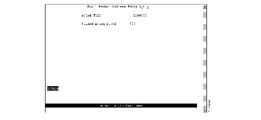
The following information is displayed on this panel:
- Table Aging Time--Time (in minutes) an inactive MAC address will remain in the master address table. Possible values are 0 through 9999 minutes. The default is 5 minutes. A value of 0 will disable the removal of addresses based on age.
- Demand Aging Level--Capacity level (expressed as a percentage of the total capacity) the master address table is allowed to reach before inactive addresses will be removed.When the threshold is reached, the addresses are cleared based on a random algorithm that is weighted to clear remote addresses first. Possible values are 50, 60, 70, 80, 90 percent, and Disable. The default is 90 percent.
|
To
| Select
| Then
|
|---|
| Change the aging time limit or the address table aging level...
| The appropriate parameter
| Specify the new value.
|
| Disable address removal based on address age...
| Aging Time
| Specify 0.
|
| Disable address removal based on address table aging level...
| Demand Aging Level
| Specify Disable.
|
| Save your changes...
| Return
|
|
The Catalyst 3900 allows you to set a password to protect its configuration. If you establish a password, users must enter it to obtain access to the Main Menu. To set a password, select Password on the Configuration Menu. The Password panel (Figure 5-36) is displayed.
Figure 5-36: Password Panel
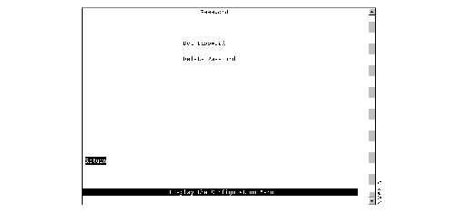
| To
| Select
| Then
|
|---|
| Add a password...
| Set Password
| Press Enter at the Old Password prompt and specify a new password.
|
| Change the password...
| Set Password
| Specify the current password and the new password.
|
| Delete the password...
| Delete Password
| Specify the current password.
|
| Save your changes...
| Return
|
|
Note If you have forgotten your password, press the System Request button to access the System Request menu, and then select Clear the system password. This will clear only the system password. All other configuration parameters saved in NVRAM will be retained.
