|
|

Product Number: GSR12-BLOWER=
This document contains instructions for installing or replacing a blower module in the Cisco 12012 Gigabit Switch Router (GSR). The Cisco 12012 is a member of the Cisco 12000 series of Internet routing products. The Cisco 12012 is aimed at scaling the Internet and enterprise backbones to speeds of OC-3/STM-1 (155 Mbps), OC-12/STM-4 (622 Mbps), and OC-48/STM-16 (2.4 Gbps). The Cisco 12012 is built around a high-speed switching fabric that is scalable from 5 to 60 Gbps, providing high-performance to support Internet Protocol (IP) -based local-area networks (LANs) and wide-area networks (WANs).
The sections in this document include the following:
The Cisco 12012 has two card cages; the upper card cage and the lower card cage. (Refer to Figure 1.) The upper card cage has 12 user-configurable slots available for line cards and a Gigabit Route Processor (GRP). One additional slot (rightmost slot) in the upper card cage is non-configurable; it is reserved for an alarm card. The line cards and the GRP are not slot dependent; you can install the line cards and the GRP in any of the first 12 available slots.
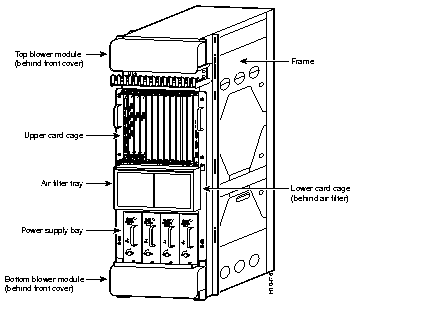
The lower card cage, located behind the air filter, has five horizontal slots for switch fabric cards.
Below the lower card cage is a power supply bay. Up to four AC-input power supplies or two DC-input power supplies can be installed in the bay.
The Cisco 12012 has two blower modules; one located above the upper card cage and one located below the power supply bay. (Refer to Figure 1.) They draw cooling air in through both card cages and the power supply bay to maintain acceptable operating temperatures for the internal components.
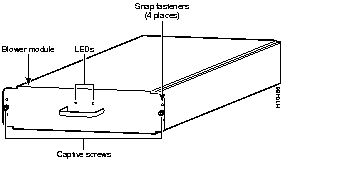
The blower module is a sheet metal enclosure containing three fans, a controller card, and two faceplate LEDs. Each blower module slides into and out the front of the frame on two rails attached to the frame. The blower modules are secured to the frame with two captive screws. Electrical connections between the blower module and the system are made through a connector at the back of the blower module.
The top and bottom blower modules (refer to Figure 2) are identical and are interchangeable. A snap-on plastic front cover is mounted over the blower module faceplate. Two blower module LEDs are visible through the front cover.
The blower module is available as a spare part. If any of the internal parts fail (fans, controller card, or LEDs), you must remove and replace the blower module.
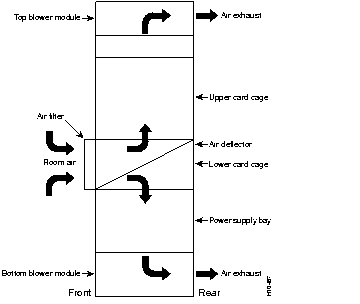
The blower modules draw room air in through an air filter on the front of the lower card cage (refer to Figure 3.) The top blower module draws the air up through the upper card cage and out through exhaust vents on the back of the blower module; the bottom blower module draws the air down through the lower card cage and power supply bay, and out through exhaust vents on the back of the blower module.
A controller card in the blower module monitors and controls the operation of the three variable-speed fans. The variable-speed feature enables quieter operation by running the fans at the speed required to maintain an acceptable operating temperature inside the card cage assembly.
Temperature sensors throughout the system monitor the internal air temperature. When the ambient air temperature is within normal operating range, the fans operate at their lowest speed, which is 55 percent of the maximum speed.
If the air temperature inside the card cage assembly exceeds the normal range, the blower module controller card increases the fan speed to provide additional cooling air to the internal components. If the temperature continues to rise, the blower module controller card linearly increases the fan speed until the fans reach 100 percent (full speed). If the internal air temperatures continue to rise beyond the specified threshold, the system environmental monitor shuts down all internal power to prevent equipment damage from excessive heat.
If the system detects that one of three fans within a blower module has failed, it displays a warning message on the console screen. In addition, the two remaining fans go to full speed to compensate for the loss of the one fan. If a second fan fails, an overtemperature condition in the card cage assembly is likely to occur.
The blower module has two LEDs (red and green) on the faceplate. (Refer to Figure 2.) The green LED, when on, indicates that the blower module's three fans are operating normally. The red LED indicates that a fault has been detected in the blower module. This fault can be one or more stopped fans, one or more fans running below speed, or the controller card has a fault.
Before you begin this installation, review the safety guidelines in this section to avoid injuring yourself or damaging the equipment.
In addition, review the safety warnings listed in the document Regulatory Compliance and Safety Information for the Cisco 12012 Gigabit Switch Router (Document Number 78-4347-xx) that accompanied your Cisco 12012 before installing, configuring, or maintaining the router.
The following guidelines will help ensure your safety and protect the equipment. This list is not inclusive of all potentially hazardous situations, so be alert.
The line cards, Gigabit Route Processor (GRP), switch fabric cards, alarm card, blower modules, and redundant power supplies are designed to be removed and replaced while the system is operating without presenting an electrical hazard or damage to the system.
Follow these basic guidelines when working with any electrical equipment:
In addition, use the guidelines that follow when working with any equipment that is disconnected from a power source, but still connected to telephone or network wiring:
Electrostatic discharge (ESD) damage, which can occur when electronic boards or components are handled improperly, can result in intermittent or complete failures.
Following are guidelines for preventing ESD damage:
 | Caution For safety, periodically check the resistance value of the antistatic strap. The measurement should be between 1 and 10 megohms. |
You need the following tools and parts to remove and replace a blower module:
This section provides the procedures you need to remove and replace a blower module.
The Cisco 12012 supports online insertion and removal of field replaceable units (FRUs), which means you can remove and replace a blower module while the Cisco 12012 remains powered up.
| Caution With the Cisco 12012 powered on and one of the blower modules removed, all of the cooling for that half of the system is lost. Remove and replace the defective blower module before the system overheats. |
| Caution Always wear an antistatic wrist strap to prevent ESD when removing and replacing a blower module. |
Perform the following steps to remove a blower module:
Step 1 Attach an ESD wrist strap to your wrist and to one of the two ESD connection sockets located on the front edges of the upper card cage or to bare metal on the frame.
Step 2 Grasp both edges of the blower module front cover and pull straight out to detach the cover from the blower module. (Refer to Figure 4.) Set the front cover aside.

Step 3 Loosen the two captive screws on the blower module faceplate. (Refer to Figure 5.)

| Caution The blower module weighs 22 lb (10 kg). Use two hands when handling a blower module. |
Step 4 Grasp the blower module handle and pull it straight out to disconnect the blower module from the frame connector. Slide the blower module halfway out of the frame.
Step 5 Place your free hand underneath the blower module for support and slide the blower module completely out of the frame.
If you plan to return the old blower module to the factory, repackage it in the shipping container you received with the replacement blower module.
Perform the following steps to replace a blower module:
| Caution The blower module weighs 22 lb (10 kg). Use two hands when handling a blower module. |
Step 1 Attach an ESD wrist strap to your wrist and to one of the two ESD connection sockets located on the front edges of the upper card cage or to bare metal on the frame.
Step 2 Using two hands to support the blower module, orient the replacement blower module in front of the frame so that the blower module connector (recessed in the back corner of the blower module) is aligned with the connector mounted on the back corner of the frame.
Step 3 Slide the blower module on the frame rails into the frame. Stop when the blower module connector makes contact with the frame connector.
Step 4 Firmly push on the blower module handle to seat the blower module connector in the frame connector. (When completely seated, the blower module faceplate flanges should be in contact with the frame.)
Step 5 Tighten the two captive screws on the blower module faceplate.
Step 6 Position the blower module front cover over the blower module faceplate. Snap the front cover onto the blower module faceplate.
This completes the blower module replacement procedure.
Proceed to the following section, "Checking the Installation," to verify that the removal and replacement procedure was performed correctly.
Complete the following steps to verify that the replacement blower module is operating properly:
Step 1 Check the following components to make sure that they are secure:
Step 2 Observe the green OK LED visible through the blower module front cover. The LED should come on as soon as the blower module is installed and power is applied to the system.
Step 3 Observe the red fail LED visible through the blower module front cover:
Step 4 Listen for the sound of the fans in the blower module. In noisy environments, it might be difficult to hear the fans operating. Place your hand at the back of the frame behind the blower module and feel for the airflow generated by the fans in the module.
If the blower module fails to operate properly, contact a service representative for assistance.
This equipment has been tested and found to comply with the limits for a Class A digital device, pursuant to part 15 of the FCC rules. These limits are designed to provide reasonable protection against harmful interference when the equipment is operated in a commercial environment. This equipment generates, uses, and can radiate radio-frequency energy and, if not installed and used in accordance with the instruction manual, may cause harmful interference to radio communications. Operation of this equipment in a residential area is likely to cause harmful interference, in which case users will be required to correct the interference at their own expense.
You can determine whether your equipment is causing interference by turning it off. If the interference stops, it was probably caused by the Cisco equipment or one of its peripheral devices. If the equipment causes interference to radio or television reception, try to correct the interference by using one or more of the following measures:
Modifications to this product not authorized by Cisco Systems, Inc. could void the FCC approval and negate your authority to operate the product.
Cisco Connection Online (CCO) is Cisco Systems' primary, real-time support channel. Maintenance customers and partners can self-register on CCO to obtain additional information and services.
Available 24 hours a day, 7 days a week, CCO provides a wealth of standard and value-added services to Cisco's customers and business partners. CCO services include product information, product documentation, software updates, release notes, technical tips, the Bug Navigator, configuration notes, brochures, descriptions of service offerings, and download access to public and authorized files.
CCO serves a wide variety of users through two interfaces that are updated and enhanced simultaneously: a character-based version and a multimedia version that resides on the World Wide Web (WWW). The character-based CCO supports Zmodem, Kermit, Xmodem, FTP, and Internet e-mail, and it is excellent for quick access to information over lower bandwidths. The WWW version of CCO provides richly formatted documents with photographs, figures, graphics, and video, as well as hyperlinks to related information.
You can access CCO in the following ways:
For a copy of CCO's Frequently Asked Questions (FAQ), contact cco-help@cisco.com. For additional information, contact cco-team@cisco.com.
|
|