|
|

This chapter provides a tutorial on using the NMT to model a simple network and contains the following sections:
The procedures explain how to input data and generate reports, as well as revise and enhance the network. Before starting this tutorial, you should review the sections "Menus" and "Keyboard Commands" in the chapter "Using the NMT."
To model a simple network, you need to describe the nodes, links, and types of traffic. Figure 3-1 illustrates a proposed network, and Table 3-1 lists the proposed connections and types of traffic. The table shows the minimum information required for effectively using the NMT.

| Site 1 (Master) | Site 2 (Slave) | Quantity | Description | Type | Status |
|---|---|---|---|---|---|
| Paris | Denver | 12 | Voice | A32 | Current |
| Denver | Boston | 8 | Voice | C32 | Current |
| Paris | Denver | 12 | Voice | L16 | Current |
| Paris | Boston | 1 | Data | L4 | Current |
| Paris | Denver | 3 | Frame Relay | V | Current |
| Paris | Boston | 10 | Frame Relay | T1 | Current |
This section describes how to input a network configuration into the NMT. In this example, we are working with an existing network, as indicated by the Status column in Table 3-1.
To model a network, perform the following steps:
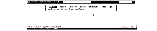
To start the NMT, type nmt at the UNIX command line. You are transferred to the NMT design window, shown in Figure 3-2.
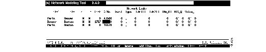
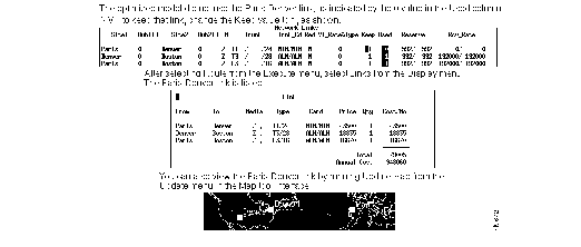
In this procedure, you enter the information shown in Table 3-2 into the Sites table.
| Site | Type | Size | Power | IGX | BC (Back Card) | FC (Front Card) | RLC (Redundant Link Card) |
|---|---|---|---|---|---|---|---|
| Paris | IGX | 32 | D | N | E1 | NTC | Y |
| Boston | IGX | 16 | A | Y | T1 | NTM | N |
| Denver | IGX | 8 | A | Y | T3 | BTM | N |
Except where noted in this table, each node uses default values. For a description of each field, see the appendix "Configuration Tables and Fields."
Step 1 Use the left and right arrows to highlight Configure and press Enter. Select Sites and press Enter. A new Sites table is displayed.
Step 2 Highlight the Site field by pressing the Down arrow. Type Paris. You have now created a site.
Step 3 To modify the NMT default site values, cursor or tab to each of the fields listed in Table 3-2 and enter the data that applies to the Paris site. There are two ways to enter data:
Step 4 Press the down arrow to insert a new line in the table.
Step 5 Repeat Step 2, Step 3, and Step 4 for Boston and Step 2 and Step 3 for Denver. The Sites table should look like the one shown in Figure 3-3.
Step 6 Press Escape to accept the entries and return to the Configure menu.

Step 1 To save your configuration, select Write from the Configure menu. Press Enter.
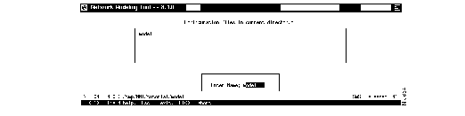
Step 2 Enter a name in the Enter Name box and press Enter. (See Figure 3-4.)
You should save your work on a regular basis.
Your file is saved and you are returned to the Configure menu.
In this procedure, you enter the information in Table 3-3 into the Links table.
| Second Screen | ||||||
|---|---|---|---|---|---|---|
| Site 1 | Site 2 | Trunk | Trunk Card Site 1/Site 2 | Reserve | Distance | $/Month |
| Paris | Denver | T1 | NTM/NTM | 592/592 | 0 | 43500 |
| Denver | Boston | T3 | ALM/ALM | 992/992 | 1767 | 0 |
| Paris | Boston | E3 | ALM/ALM | 992/992 | 0 | 16670 |
Except where noted in this table, each link uses default values. For a description of each field, see the appendix "Configuration Tables and Fields."
Step 1 Select Links from the Configure menu and press Enter. A new Links table is displayed.
Step 2 Highlight the Site 1 field by pressing the Down arrow. Type Paris. Cursor or tab to the Site 2 field and enter Denver. If you are inputting site names by pressing the Help key, use the up and down arrows to scroll through the site names. Press Enter to select the site.
Step 3 Cursor or tab to each of the fields listed in Table 3-3, and enter the data that applies to the Paris/Denver link.
To go to the Distance and $/Month fields, press F5, which takes you to the second screen of the Links table. (Press Escape to return to the previous screen.)
Step 4 Press the down arrow to insert a new line in the table.
Step 5 Repeat Step 2, Step 3, and Step 4 for the Denver/Boston link and Step 2 and Step 3 for the Paris/Boston link. The Links table should look like the one shown in Figure 3-5.
Step 6 Press Escape to accept the entries and return to the Configure menu.You may have to press Escape two times.
For NMT to assist you in modeling a network, you must describe the traffic. The network in this tutorial uses voice, data, and bursty traffic.
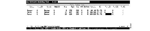
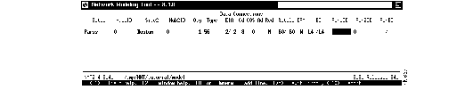
In this procedure, you enter the information shown in Table 3-4 into the Voice Connections table.
| Site 1 | Site 2 | Quantity | Type | Utilization Site 1/Site 2 |
|---|---|---|---|---|
| Denver | Boston |
|
C32 | 40/40 |
| Paris | Denver |
|
A32 | 100/100 |
| Paris | Denver |
|
L16 | 100/100 |
Except where noted in this table, each link uses default values. For a description of each field, see the appendix "Configuration Tables and Fields."
Step 1 Select Voice Traffic from the Configure menu and press Enter. A new Voice Connections table is displayed.
Step 2 Highlight the Site 1 field by pressing the down arrow. Type Denver. Cursor or tab to the Site 2 field and enter Boston.
Step 3 Cursor or tab to each of the fields listed in Table 3-4 and enter the data that applies to the Denver/Boston connection.
Step 4 Press the down arrow to insert a new line in the table.
Step 5 Repeat Step 2, Step 3, and Step 4 for the first Paris/Denver link and Step 2 and Step 3 for the second Paris/Denver link. The Voice Connections table should look like the one shown in Figure 3-6.
Step 6 Press Escape to accept the entries and return to the Configure menu.
In this procedure, you enter the information shown in Table 3-5 into the Data Connections table.
| Site 1 | Site 2 | Quantity | Utilization Site 1/Site 2 | Back Card Site 1/Site 2 |
|---|---|---|---|---|
| Paris | Boston |
|
60/60 | L4/L4 |
Except where noted in this table, each link uses default values. For a description of each field, see the appendix "Configuration Tables and Fields."
Step 1 Select Data Traffic from the Configure menu. A new Data Connections table is displayed.
Step 2 Highlight the Site 1 field by pressing the Down arrow. Type Paris. Cursor or tab to the Site 2 field and enter Boston.
Step 3 Cursor or tab to each of the fields listed in Table 3-5 and enter the data that applies to the Paris/Boston connection. The Data Connections table should look like the one shown in Figure 3-7.
Step 4 Press Escape to accept the entries and return to the Configure menu.
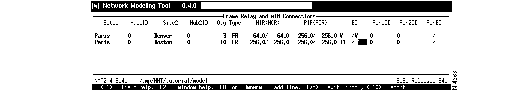
In this procedure, you enter the information shown in Table 3-6 into the Frame Relay and ATM Connections table.
| Site 1 | Site 2 | Quantity | MIR (Minimum Information Rate) | PIR (Peak Information Rate) | BC (Back Card) |
|---|---|---|---|---|---|
| Paris | Denver |
|
64/64 | 256/256 | V/V |
| Paris | Boston |
|
256/256 | 256/256 | T1/T1 |
Except where noted in this table, each link uses default values. For a description of each field, see the appendix "Configuration Tables and Fields."
Step 1 Select Bursty Traffic from the Configure menu. A new Frame Relay and ATM Connections table is displayed.
Step 2 Highlight the Site 1 field by pressing the down arrow. Type Paris. Cursor or tab to the Site 2 field and enter Denver.
Step 3 Cursor or tab to each of the fields listed in Table 3-6 and enter the data that applies to the Paris/Denver connection.
Step 4 Press the down arrow to insert a new line in the table.
Step 5 Repeat Step 2 and Step 3 for the Paris/Boston connection. The Frame Relay and ATM Connections table should look like the one shown in Figure 3-8.
Step 6 Press Escape to accept the entries and return to the Configure menu.
When you leave the Configure menu, the NMT checks your input. If the program identifies any problems, it instructs you to check your Warning browser. To view warnings:
Step 1 Press Escape to exit the Configure menu. A message box displays the following message: "Checking current configuration; New warning messages generated. Check your warning browser."
Step 2 Select Warnings & Errors from the Display menu. The Warnings browser shows that the NMT modified the capacity of trunks as listed in the Links table. (See Figure 3-9.)
For more information on the Warnings browser, see "Modeling Processes" in the chapter entitled "Using the NMT."
Step 3 Press Escape twice to exit from the Warnings browser and the Display menu.

This section describes how to optimize your configuration and perform failure analysis to add resiliency to your network.
When you select Optimize, the NMT processes your configuration to design a least-facilities-cost network. Selecting Optimize eliminates any unused links (links that are not used for routing traffic) from the topology. These unused links remain in the Links table for possible later use.
The following procedure describes how to use the Optimize facility to review the optimized model and add a resilient link to the optimized model.
Step 1 Select Optimize from the Execute menu. Press Enter.
When you run Optimize it performs several steps, each of which displays a message window. First, the system calculates a topology in which all traffic is routed at the lowest possible cost. Second, the NMT builds the site. Third, the connections are routed. Fourth, the program generates reports. For a complete description of the Optimize process, see the section "Model Optimization Methods" in the chapter entitled "Using the NMT."
Press Escape until you exit the Execute menu.
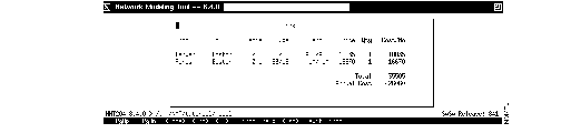
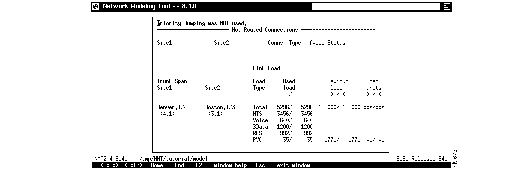
Step 2 Select Links from the Display menu to display the results in a table format. Press Enter to display the results (Figure 3-10).
Only two links are listed (Denver/Boston and Boston/Denver) because the NMT calculated that it is cheaper to go from Paris to Denver by way of Boston, than to go directly from Paris to Denver. This calculation was based on the information you entered in the Distance and $/Month fields in the Links table.
Press Escape to exit the Links display.
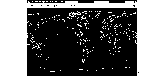
Step 3 To create a graphic representation of the topology
(a) Select Map from the Display menu to display the results graphically. It may take several seconds for the Map window to display.
(b) Click on the Update menu in the Map menu bar. Click on Update Map.
(c) Click on the menu bar Map button and choose Select. Select the world map from the list. (This command also returns a map to its default size.)
(d) Drag the icons Paris, Denver, and Boston to their respective locations. The icons are small boxes initially stacked in the upper left corner of the Map window. Drag each icon to a new location by holding down the left mouse button and moving the mouse.
(e) To save this map, select Save from the menu bar Utility menu.
The map shows that the optimized configuration consists of only two links (Paris/Boston and Boston/Denver). See Figure 3-11.
Step 4 Go to the Network Modeling Tool window and select Links from the Configure menu. (You may need to first press Escape to exit from the Display menu.)
Cursor or tab to the Keep field of the Links table. Set all the Keep values to 1.
By changing the Keep value from 0 to 1, you instruct the NMT to create a resilient link--traffic can still be routed even if one link goes down. In this example, the resilient link is Paris to Denver.
Press Escape until you exit the Configure menu.
Step 5 Select Route from the Execute menu to instruct the NMT to create routes for as many Link table entries as possible.
The Route command creates routes for each entry in the Links table that has a Keep field value of 1 or more. For a complete description of the Route process, see the section "Model Optimization Methods" in the chapter "Using the NMT."
Press Escape.
Step 6 Repeat Step 2 to Display your results. If the map window is still open, repeat Step 3b. If the window is closed, repeat Steps 3a and 3b. Observe that both the links display and the topology map now include a Paris to Denver link. (See Figure 3-12.)
Adding resiliency to a network is seldom as simple as looking at the topology and making sure the nodes are connected. Utilization rates, bandwidth, delay factors, and more must be taken into account before you or the NMT can determine if a link is resilient. The NMT can compute which lines have enough extra bandwidth, according to values input in the configuration, to support extra traffic in the event a line goes down.
The following procedure demonstrates how to do failure analysis in the NMT.
Step 1 Select Optimize from the Execute menu. (You must select Route or Optimize before running failure analysis.) Press Enter twice. For a complete description of the Optimize process, see the section "Model Optimization Methods" in the chapter "Using the NMT."
Step 2 Select Fail Analysis from the Execute menu. This calls up a submenu.
Step 3 Select Fail Line from the Fail Analysis submenu. The Fail Line table appears.
Step 4 Change N to Y in the first line of the Fail Line table to tell the NMT to fail the link between Paris and Denver.
Press Escape to return to the Fail Analysis submenu.
Step 5 Select Alt-Route from the Fail Analysis submenu to process the change you made in the previous step. Press Enter.
Press Escape until you return to the Fail Analysis submenu.
Step 6 Select Results from the Fail Analysis submenu. (See Figure 3-13.)
The table shows the following:
Step 7 Go to the Map window and click on the Update menu in the Map menu bar. Click on Update Map. (For more information, see the instructions for using the Map tool in the section "Optimizing Your Configuration" earlier in this chapter.)
Notice that the Paris to Denver link is displayed in red. This indicates that the link is down according to the last failure analysis run.
The Simulate All menu selection allows you to perform a failure analysis for each link, one at a time.
Step 1 Select Route from the Execute menu and press Enter. When the routing process stops, press Enter again. Press Escape.
Step 2 Select Simulate All from the Fail Analysis submenu.
Step 3 Enter a file name. Press Enter.
Step 4 Press Escape until you exit the Execute menu.
Step 5 Select View from the Report menu and select the file name you chose in Step 3.
This report first shows the link loads for all links with no link failures. Then it displays the connections not routed and the link loads for each link failure. (If you select Results from the Fail Analysis submenu in the Execute menu or View Results from the Display menu, you will see the results of only the last link failure.)
|
|