|
|

This chapter describes the trunk cards that interface to the network. The IPX supports both Asynchronous Transfer Mode (ATM) trunks and FastPacket (FP) trunks. ATM trunks are supported by the ATM Internetworking Trunk (AIT) front and back card set.
FastPacket trunks are supported by the NTC front card and one of the following back cards:
The chapter contains the following:
The ATM trunks transmit data in 53-byte cells over T3 or E3 lines to another AIT in an IPX, or to a BNI in the BPX. While the AIT trunk is T3/E3, the maximum data rate to the AIT is throttled down to 8000 packets per second because of MuxBus limits.
The AIT card set consists of a front card and a back card and is used for IPX to IPX and IPX to BPX traffic using ATM cell relay protocol over a single T3 or E3 trunk.
The AIT Card Set consists of an AIT front and either a T3 or E3 AIT backcard.
The IPX card set can be used to:
The AIT card set provides a single T3 or E3 ATM port for an IPX node. The card set consists of a front card (AIT-FC) and a back card (AIT-BC). Each card occupies a single slot in an IPX node. The cards connect through the Local Bus 2 utility bus.
The AIT front card is connected to the node through the MUXBUS for data (in FastPacket format) and the CBUS for control. The front card provides interfaces to the MUXBUS and CBUS, controls the back card, and performs the necessary routing and computation on the data streams. A RISC module attached to the front card performs the computation. The front card contains four LED indicators that indicate status and alarm conditions.
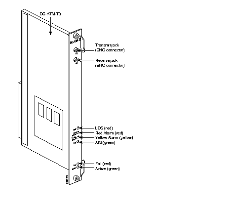
The AIT back card is available in two versions. One version supports a single ATM T3 port, and the other supports a single ATM E3 port. The back card provides the interface to the trunk line and performs all necessary CRC generation and checking. The trunk port consists of two BNC connectors (one for transmit and one for receive). The back card contains six LED indicators that indicate the status of the port and various alarm conditions (see below for details).
The AIT card set operates in either of two gateway modes, Simple Gateway or Complex Gateway.
The Simple Gateway mode is used when the AIT card set performs FastPacket/ATM interworking. In this mode, the card set permits the IPX node to perform bi-directional transmission of FastPackets by encapsulating them in ATM cells over ATM trunks. The Simple Gateway can be used for both IPX to IPX and IPX to BPX transmissions.
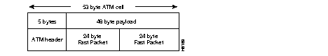
When operating as a simple gateway, FastPackets containing any valid type of FastPacket data (including frame relay, data, voice, etc.), are received by the AIT front card over the Muxbus. The AIT assembles the data, two consecutive packets at a time, to provide the payload for an ATM cell. The AIT card waits only a predefined time period for the second packet. If the second packet is not received when the time period expires, the cell is transmitted with only the first packet as the payload. The two 24-byte FastPackets comprise the 48-byte cell payload as shown in Figure 3-1.
Simple Gateway uses a StrataCom proprietary ATM header (STI) as shown in Figure 3-2.
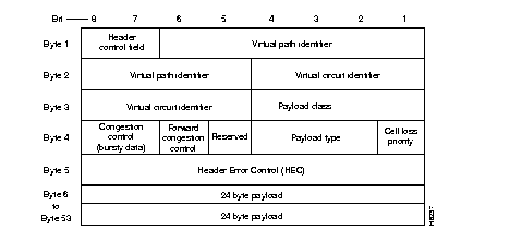
The payload type determines the queue into which the traffic is placed. Table 3-1. lists the payload types.
| Queue | Traffic types |
|---|---|
| High Priority | NPC, First 2 packets of voice |
| Non-Time-Stamped Data | Data > 56 Kbps, "a", "t" voice, modem |
| Time-Stamped Data | Data £ 56 Kbps |
| Voice and ADPCM | "c", "v" voice |
| Bursty Data | Frame relay |
The Complex Gateway mode is used when the AIT card set performs Frame Relay to ATM interworking (ATF). In this mode, frame relay data received over the Muxbus is extracted from the FastPackets (which are discarded) and inserted into the payload portions of consecutive ATM cells for transmission over the ATM trunk. Similarly, frame relay data is extracted from cells received over the trunk and is inserted into FastPackets for transmission over the MuxBus.
The Complex Gateway provides an efficient method for transmitting frame relay data over broadband trunks, and it allows users to migrate to ATM as their bandwidth needs expand.
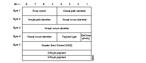
The Complex Gateway is used only for transporting frame relay connections across an ATM network. The ATM UNI header is used by the Complex Gateway (Figure 3-3), and the payload is formatted as AAL5 for bursty data.
The Complex Gateway performs frame relay to ATM address mapping as follows. For frame relay data received over the Muxbus, the frame relay address is converted to a VPI/VCI field of the ATM cell header. For ATM cells received over the AIT trunk, the VCI field in the ATM header is converted to the DCLI of the frame relay FastPacket.
Operation and Maintenance (OAM) cells (except level F4) are supported by the Complex Gateway mode.
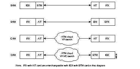
The AIT(IPX) or BTM(IGX) can operate in several different addressing modes selected by the user (see Table 3-2 and Figure 3-4). In the BPX Addressing Mode (BAM), used for all StrataCom networks, the system software determines VPI and VCI values for each connection that is added to the network. The user enters the beginning and end points of the connection and the software automatically programs routing tables in each node that will carry the connection to translate the VPI/VCI address. The user does not need to enter anything more. This mode uses the STI header format and can support all of the optional StrataCom features.
To allow the IPX or IGX to be used in mixed networks with other ATM switches, there are two other addressing modes available, Cloud Addressing Mode (CAM) and Simple Addressing Mode (SAM). In the Simple Addressing Mode, the user must manually program the path whole address, both VPI and VCI values. The Cloud Addressing Mode is used in mixed networks where the virtual path addresses are programmed by the user and the switch decodes the VCI address. Both CAM and SAM utilize the UNI header type.
| Addressing Mode | Hdr. Type | Derivation of VPI/VCI | Where Used |
|---|---|---|---|
| BAM--BPX Addressing Mode | STI | VPI/VCI = Node Derived Address | Between IPX (or IGX) and BPX nodes, or between IPX (or IGX) nodes. |
| CAM--Cloud Addressing Mode | UNI | VPI = User Programmed VCI = Node Derived Address | IPX to IPX (or IGX) connections over networks using ATM switches that switch on VPI only. VPI is manually programmed by user. Terminating IPX converts VCI address to FastPacket address. |
| SAM--Simple Addressing Mode | UNI | VPI/VCI = User Programmed | IPX to IPX (or IGX) connections over networks using ATM switches that switch where all routing is manually programmed by user, both VPI and VCI. |
The AIT backcard provides a variety of CRC checking and generation algorithms to support the two gateways as follows:
The front panel of the AIT front card has four LEDs. An ACTIVE LED indicates the card is active and functioning normally. An AIT card failure triggers the FAIL LED.
The other two LEDs are summary alarms for the back card conditions. A yellow MINOR LED indicates non-service interrupting faults or incidents of error statistics that exceed a preset threshold. A red MAJOR LED indicates service-affecting failures.
The AIT back card has six LED indicators as shown in Figure 3-5 and Table 3-3.
| Connector/Indicator | Function |
|---|---|
| FAIL light (red) | Indicates that a failure has been detected on the card and that the card cannot reliably carry data. The card must be replaced. |
| ACTIVE: light (green) | Indicates that the card is in service and that active circuits are present. |
| LOS light (red) | Indicates loss of signal at the local end. |
| Red Alarm light (red) | Indicates loss of local T3 or E3 frame alignment, or cell alignment. |
| Yellow Alarm light (yellow) | Indicates loss of frame alignment at remote end, or cell alignment. |
| AIS light (green) | Indicates the presence of all ones on the line. |
AIT cards support Y-cable redundancy on ATM trunks in IPX-to-IPX and IPX-to-BPX applications.
Y-Cable Redundancy requires the redundant card set to be in a physically adjacent slot and that both cards be upped (uptrk) and added (addtrk) before redundancy is assigned.
The AIT card performs a clock test on the input line source. If either the clock or card fails, a switch occurs to a Y-cabled redundant AIT trunk card set if available. If the switch occurs, the primary ATM trunk card is failed, and the red FAIL indicator is turned on. If Y-cable redundancy is not available, the ATM trunk switches to another clock source and marks the line as a failed clock source.
The AIT front and back cards are installed in combination with the standard Local Bus (LB2). The T3/E3 connections are BNC type connectors. The transmit jack is the upper of the two connectors.
 | Caution To prevent damage to the cards, ground yourself before handling IPX cards by putting on a wrist strap and clipping the wrist strap lead to the cabinet enclosure. |
No maintenance is required on AIT card except for replacement after failure. The AIT cards are considered trunks for purposes of troubleshooting. The tstcon command does not work on an AIT card since the card cannot be isolated from the BPX or other connecting ATM trunk.
A trunk loopback test is run when an ATM trunk detects an integrated alarm. The loopback test indicates if the line or the card is faulty. A loopback test "pass" means the line is faulty, and a line alarm is indicated. A loopback test "fail" means the card is faulty. In the case of a faulty card, a switch occurs to an available Y-Cable equipped redundant card.
The AIT trunk card are recognized by the appropriate existing trunk commands, and the screens display the appropriate information for the cards. Refer to the Command Reference for command and screen details.
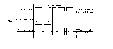
Each Network Trunk Card (NTC) in an IPX coordinates FastPacket data transmission out on a trunk line to an IPX at the other end of the connection. The multifunction NTC card performs a variety of important IPX operations. Included in its functions, the NTC:
An NTC can reside in any of the IPX 16/32 front slots 2-16 and 18-32 or the IPX 8 front slots 3 - 8. This front card must be used with a corresponding BC back card. A local utility bus (LB00) connects the NTC and back card. In an IPX 32 node, up to 14 E1 or 16 T1 trunk line interfaces to NTCs are possible. The IPX 8 can have up to 6 trunk line interfaces with NTCs.
The NTC is a front card that interfaces with four different types of back cards. The choice of back card depends on the trunk interface type.
Fractional T1 trunk lines can be interfaced by using an NTC Model B or later with a BC-T1 back card. Fractional trunk interfaces use a specific group of 64 Kbps channels that constitute a partial T1 trunk. For example, a 512 Kbps fractional T1 trunk might use every third channel from 1 through 24. The network operator assigns the channels.
The NTC supports subrate trunks when used with a BC-SR back card and appropriate local bus. Subrate trunks interface to the digital transmission facility at specified trunk rates that range from 64 Kbps to 1.92 Mbps. Unlike fractional trunks, which use a basic trunk frequency such as 1.544 Mbps for the clock rate, the clock rate used by a subrate trunk is the same as the subrate--256 Kbps for a 256 Kbps subrate trunk, for example.
The NTC implements a unique link protocol for framing packets on the trunk. To avoid any dependency on the particular framing pattern of the trunk, the NTC uses a packet framing scheme based on the CRC in the FastPacket.
The FastPacket format has a five-bit CRC field in the least significant bits of the third byte. This CRC covers the first four bytes of the packet header. This framing algorithm uses the CRC to detect the packet boundaries. No additional trunk bandwidth is required to do framing. This algorithm allows the IPX packet to be independent of the trunk frame structure and thus allows the full utilization of the available bandwidth and even permits the NTC to use unframed trunks.
The NTC and a BC-E1, BC-T1, BC-SR, and BC-Y1 can be configured for 1:1 redundancy by using a second, identical, card set for the redundant pair and a Y-cable for connection to the packet or circuit line.
The NTC Model C (and later) facilitates the full utilization of NTC operation. The selection of the local bus depends on which back card is installed.
The front panel of the NTC card has four LEDs. An ACTIVE LED indicates the card is active and functioning normally. An NTC card failure triggers the FAIL LED.
The other two LEDs are a summary alarm for the back card conditions. A yellow MINOR LED indicates either a non-service interrupting fault or that error statistics have exceeded a preset threshold. A red MAJOR LED indicates a service-affecting failure. The alarms and line conditions monitored by the NTC include:
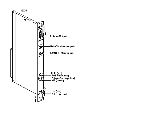
The T1 Trunk Interface Card (BC-T1) card (Figure 3-6 and Table 3-4) terminates a single 1.544 Mbps T1 trunk line on the NTC. The BC-T1 can reside in any of the rear slots 2-16 or 18-32 of the IPX 16/32 (3-8 of the IPX 8). It connects to the NTC through the Local Bus (LB) and can be made redundant by providing a standby unit and using a Y-cable at the input/output connector.
The BC-T1 has the following features:
B8ZS supports 64 Kbps clear channel operation because B8ZS eliminates the possibility of a long string of zeros. B8ZS is preferable whenever available, especially on trunks.
The BC-T1 supports two clock modes. These are normal clocking and loop timing. The system operator selects the mode through software control. Normal clocking uses the receive clock from the network for incoming data and supplies the transmit clock for outgoing data. This clock can be used to synchronize the node.
Loop timing uses the receive clock from the network for the incoming data and turns the receive clock around for timing the transmit data.
Refer to Figure 3-6 and Table 3-4 for the front plate features of the BC-T1. The standard port connector is a DB15 female. The BC-T1 and BC-E1 indicator lamps are similar, but the BC-T1 does not have multiframe alignment (MFRA and MFYA) alarms.
| No. | Connector/Indicator | Function |
|---|---|---|
| 1. | FAIL light (red) | Indicates that an error occurred. Resetting the card with the resetcd f command is suggested first. If the LED comes on again, call the Customer Service. |
| 2. | ACTIVE: light (green) | Indicates that the card is in service and that active circuits are present. |
| 3. | LOS light (red) | Indicates loss of signal at the local end. |
| 4. | Red Alarm light (red) | Indicates loss of local E1 frame alignment, or packet alignment (NTC). |
| 5. | Yellow Alarm light (yellow) | Indicates loss of frame alignment at remote end, or packet alignment (NTC). |
| 6. | AIS light (green) | indicates the presence of all ones on the line. |
| 7. | T1 INPUT/OUTPUT | DB15 connector for T1 line. |
| 8. | RX MON | BNC test connector for monitoring receive T1 line. |
| 9. | TX MON | BNC test connector for monitoring transmit T1 line. |
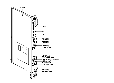
The E1 Trunk Interface Card (BC-E1) provides an E1 trunk interface for the Network Trunk Card (NTC) and the Channelized Data PAD (CDP). The BC-E1 can reside in any of the rear slots 2-16 or 18-32 of the IPX 16/32 (slot 3-8 of the IPX 8). It connects to the NTC or CDP through the Local Bus, (LB). See Table 3-5 for a list of controls and indicators.
The BC-E1 supports the following:
Figure 3-7 shows the BC-E1 front plate connectors and indicators, and Table 3-5 describes them.
| No. | Connector/Indicator | Function |
|---|---|---|
| 1. | FAIL light (red) | Indicates that a failure has been detected on the card and that the card cannot reliably carry data. The card must be replaced. |
| 2. | ACTIVE: light (green) | Indicates that the card is in service and that active circuits are present. |
| 3. | LOS light (red) | Indicates loss of signal at the local end. |
| 4. | Red Alarm light (red) | Indicates loss of local E1 frame alignment or packet alignment (NTC). |
| 5. | Yellow Alarm light (yellow) | Indicates loss of frame alignment at remote end or packet alignment (NTC). |
| 6. | AIS light (green) | Indicates the presence of all ones on the line. |
| 7. | MFRA light (red) | Indicates loss of multiframe alignment (E1 only). |
| 8. | MFRY light (yellow) | Indicates loss of multiframe at the remote end (E1 only). |
| 9. | RX | BNC connector for receive E1 line (alternate to #9). |
| 10. | TX | BNC connector for transmit E1 line (alternate to #9). |
| 11. | RX MON | BNC test connector for monitoring receive E1 line. |
| 12. | TX MON | BNC test connector for monitoring transmit E1 line. |
| 13. | RX-TX | Female DB15 connector for XMT and RCV E1. |
The BC-E1 supports two clock modes. These are normal clocking and loop timing. The system operator selects the mode through software control. Normal clocking uses the receive clock from the network for incoming data and supplies the transmit clock for outgoing data. This clock can be used to synchronize the node.
Loop timing uses the receive clock from the network for the incoming data and turns the receive clock around for timing the transmit data.
Statistics are kept on most line errors and fault conditions, including the following:
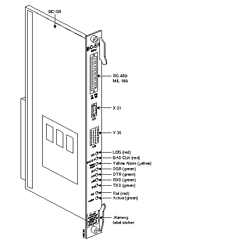
The Subrate Trunk Interface Card (BC-SR) card is used for terminating only subrate trunks on the NTC. The subrate trunk uses only a portion of the full E1 or T1 bandwidth and is used primarily as tail circuitry or where little traffic exists. The subrate trunk interface is a DCE interface, and the subrate channel acts like a synchronous data channel. Therefore, the IPX subrate back card must always be configured as a DTE. Only leased lines are supported; dial-up lines are not supported.
The BC-SR supports the following:
Note that subrate trunks cannot pass clocks between nodes.
Refer to Figure 3-8 and Table 3-6 for descriptions of controls and indicators on the BC-SR front plate. The data signals and EIA leads supported by the subrate interface appear in Table 3-7. The following alarm conditions are monitored and displayed for subrate trunks:
| No. | Connector/Indicator | Function |
|---|---|---|
| 1. | FAIL light (red) | Indicates that a failure has been detected on the card and that the card cannot reliably carry data. The card must be replaced. |
| 2. | ACTIVE: light (green) | Indicates that the card is in service and that active circuits are present. |
| 3. | LOS light (red) | Indicates loss of signal at the local end. |
| 4. | Bad CLK light (red) | Indicates loss of clock or clock out of range. |
| 5. | Yellow Alarm light (yellow) | Indicates loss of frame alignment at remote end, or packet alignment (NTC). |
| 6. | DSR light (green) | Indicates the DSR lead is high (ON). |
| 7. | DTR light (green) | Indicates the DTR lead is high (ON). |
| 8. | RXD light (green) | Indicates the receive data line shows activity. |
| 9. | TXD light (green) | Indicates the transmit data line shows activity. |
| 10. | RS-449 data connector | DB37 female connector. |
| 11. | X.21 data connector | DB15 female connector. |
| 12. | V.35 data connector | 34-pin female MRAC connector. |
| Transmit | Receive | ||||
|---|---|---|---|---|---|
| Lead | Name | Interface | Lead | Name | Interface |
| TX | Transmit data | All | RX | Receive data | All |
| RTS | Request to Send | 188, V.35 | CTS | Clear to Send | 188, V.35 |
| DTR/C | Data Terminal Ready | All | DSR/I | Data Set Ready | All |
| LL | Local Loop | 188 | DCD | Data carrier select | 188, V.35 |
| RL | Remote Loop | 188 | RI/IC | Ring Incoming Call | 188, V.35 |
| IS | Terminal In Service | 188 | TM | Test mode | 188. V.35 |
| SS | Select standby | 188, V.35 | SB | Standby indicator | 188 |
| SF | Sig rate select | 188 | SI | Signalling rate | 188 |
The BC-Y1 back card provides a Japanese Y1 trunk interface for an NTC (Figure 3-9). The BC-Y1 is a standard IPX back card and can reside in rear slot 2-16 or 18-32 of the IPX node, and the NTC must reside in the corresponding front slot. The two cards connect through the Local Bus (LB00). The BC-Y1 supports the following:
The BC-Y1 supports two clock modes. These are normal clocking and loop timing. The system operator selects the mode through software control. Normal clocking uses the receive clock from the network for incoming data and supplies the transmit clock for outgoing data. This clock can be used to synchronize the node.
Loop timing uses the receive clock from the network for the incoming data and turns the receive clock around for timing the transmit data.
Refer to Figure 3-10 and Table 3-8 for descriptions of controls and indicators on the BC-Y1 connectors and indicators.
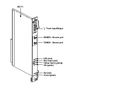
| No. | Connector/Indicator | Function |
|---|---|---|
| 1. | FAIL light (red) | Indicates that a failure has been detected on the card, and that the card cannot reliably carry data. The card must be replaced. |
| 2. | ACTIVE light (green) | Indicates that the card is in service and that active circuits are present. |
| 3. | LOS light (red) | Indicates loss of signal at the local end. |
| 4. | Red Alarm light (red) | Indicates loss of local frame alignment. |
| 5. | Yellow Alarm light (yellow) | Indicates loss of frame alignment at the remote end. |
| 6. | AIS light (green) | Indicates the presence of all ones on the line. |
| 7. | Y1 Trunk INPUT/OUTPUT | DB15 connector for Y1 Trunk |
| 8 | RX MON | BNC test connector for monitoring receive Y1 line |
| 9. | TX MON | BNC test connector for monitoring transmit Y1 line |
|
|