|
|
This chapter provides information on the Catalyst 5000 series switching system. The information is organized into the following sections:
http://www.cisco.com. For more information, see the chapter "Documentation" at the end of the catalog.
The Catalyst 5000 series is a modular switching system that provides high-density switched Ethernet and Fast Ethernet interfaces for wiring closet and data-center applications. The Catalyst 5000 series system provides virtual LAN networking and optional multilayer switching with Cisco Internetwork Operating System (Cisco IOS) software functionality. The modular design allows you to dedicate 10-Mbps Ethernet and 100-Mbps Fast Ethernet connections to existing LAN segments or high-performance workstations and servers using unshielded twisted-pair (UTP), shielded twisted-pair (STP), and fiber-optic cable. The switch architecture includes a single integrated 1.2 gigabits-per-second data switching backbone that supports wire-speed switched Ethernet and Fast Ethernet users across a wide range of backbone interfaces including Fast Ethernet, Fiber Distributed Data Interface (FDDI), and ATM.
The five-slot, modular chassis of the Catalyst 5000 series features fault-tolerant power with a dual AC power supply option and a full complement of hot-swappable interface modules. (Hot-swappable means that all system components can be removed, added, or changed without rebooting or taking the system off line.) The five module slots support the required Supervisor Engine and, in the remaining four slots, any of the following interface modules:
The new 12-port 100BaseFX single-mode/multimode fiber switching module provides six single-mode and six multimode fiber connections for connecting switching systems across a campus or across a city.

The ATM LAN Emulation dual PHY module delivers fault tolerance for critical network applications via two unique features:
The Supervisor Engine enables Layer 2 switching and network management. This module contains two Fast Ethernet interfaces to connect to workstations, servers, switches, and routers. The Catalyst 5000 series system can accommodate up to 192 group switched Ethernet interfaces, 96 switched Ethernet interfaces, and up to 50 Fast Ethernet interfaces.
The 10BaseT 48-port group switching Ethernet module provides a method to divide users into managed switch groups. Group switching combines hub costing and network management on one module; it is an alternative to shared-media hubs. Each module has four 10BaseT Ethernet segments with groups of 12 users per segment (48 interfaces per module). You can switch each group of 12 ports to any Catalyst 5000 VLAN. The 10BaseT Ethernet switch module supports 24 dedicated segments; each can be assigned to a different VLAN. The 10/100BaseTX module supports auto-negotiation, which sets the appropriate speed and duplex mode (half or full) for the switched connection and adapter interface. This variety of interface modules offers the flexibility to accommodate today's dynamic network topologies and the scalability to meet bandwidth, speed, and application advancements today and in the future.
The Catalyst 5000 series system has a number of features that contribute to its superior traffic management capabilities. The switch is fully nonblocking for 10-Mbps Ethernet and is capable of switching over 1 million packets per second. Ethernet to Ethernet, Fast Ethernet, or ATM packet latency is less than 10 microseconds. Ethernet to FDDI packet latency is 100 microseconds. The data switching bus supports three priority queues so that you can define priorities on a per-port basis.
The Catalyst 5000 series system supports the formation of workgroups within and between other Catalyst 5000 series switches. One thousand VLANs can be maintained across switching and routing platforms through Fast Ethernet, CDDI/FDDI, and ATM connections. Any Fast Ethernet interface on the Catalyst 5000 series system can be configured as an InterSwitch Link (ISL) to support multiple VLANs. Note that all VLANs support the IEEE 802.1d spanning-tree algorithm for fault-tolerant connections. ATM supports VLANs by emulating the LANs into virtual circuits. FDDI supports 802.10 for multiple VLANs.
The switch can be configured through a command-line interface or a GUI-based management application. The command-line interface can be accessed out-of-band by an ASCII terminal or modem and in-band using Telnet or SNMP commands through any LAN or ATM interface. CiscoWorks for Switched Internetworks network management application can be used to query all Cisco products, including the Catalyst 5000 series system physical view, as well as configure, monitor, and troubleshoot the system. The VlanDirector management application allows you to perform drag-and-drop configuration of your network based on logical user groups and display an enterprise-wide logical view of these groups. The TrafficDirector management application allows you to monitor and troubleshoot networks using standard RMON technology.

The Catalyst 5000 series base system includes the following standard features:
Figure 111 : Catalyst 5000 Series Front Panel
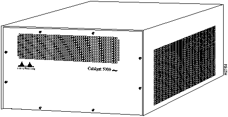
Figure 112 : Catalyst 5000 Series Rear Panel
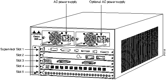
Table 248 : Catalyst 5000 Series Summary of Features
| Characteristics | Description |
|---|---|
| Placement | Rack-mounted, front or back (standard 19-inch rack) |
| Switching backplane | 1.2-Gbps, supports over 1 million packets per second (pps) |
| Memory | 4-MB Flash memory
8-MB DRAM 256-KB NVRAM 512-KB EPROM |
| Interfaces | Supervisor console: DB-25 (female)
Supervisor 100BaseTX: RJ-45 (female), MII 1(female) Supervisor 100BaseFX: MMF (SC), SMF (SC) 10BaseT: RJ-21 (female, Telco) 10BaseFL: ST (female) 100BaseTX: RJ-45 (female) 10/100BaseTX: R5-45 (female) 100BaseFX: MMF (SC), SMF (SC) CDDI: RJ-45 (female) FDDI: MMF (MIC), SMF (ST) Optical bypass switch connector: 6-pin mini-DIN ATM:RJ-45, MMF (SC), SMF (SC) |
| Duplex | 10-Mbps Ethernet: Full or half duplex
100-Mbps Fast Ethernet: Full or half duplex 10/100-Mbps Fast Ethernet: Auto-negotiated speed and duplex FDDI: Half duplex ATM: Full duplex |
| Network management | Cisco Discovery Protocol
VLAN Trunk Protocol SNMP agent v1 (RFC 1155-1157) SNMP MIB II (RFC 1213) Telnet Client RMON (4 groups) Ethernet MIB (RFC 1398) Interface Table (RFC 1573) Bridge MIB (1493) FDDI MIB (RFC 1512) SMT 7.3 (RFC 1285) AToMIC MIB (RFC 1695) ILMI MIB Cisco Workgroup MIB LEC MIB (ATM Forum LANE v1.0) Cisco LECS MIB Cisco LES/BUS MIB |
| Maximum station-to-station cabling distance | 10BaseT Ethernet: Category 5 UTP: 328' (100 m)
10BaseFL Ethernet: 62.5/125-micron fiber: 1.24 miles (2 km) 100BaseTX Fast Ethernet: Category 5 UTP: 328' (100 m) 10/100BaseTX Fast Ethernet: Category 5 UTP: 328' (100 m) 100BaseFX Fast Ethernet: 62.5/125 multimode fiber (400 m half duplex, 2 km full duplex) 8.7/125 single mode fiber (10 km full or half duplex) CDDI: Category 5 UTP: 328' (100 m) FDDI: 62.5/125 multimode fiber, 2 km 8.7/125 single mode fiber, 10 km ATM LAN emulation module UTP: Category 5 UTP: 328' (100 m) ATM LAN emulation module multimode fiber: 62.5/125 micron fiber, 2 km ATM LAN emulation module single mode fiber: 8.7/125 micron fiber 10 km |
| Fiber optical specifications | The following multimode specifications are applicable to Catalyst 5000 line modules WS-X5005, WS-X5011, WS-X5155, WS-X5114, WS-X5101, WS-X5158:
Transmitter output power: --19 to --14 dBm Receiver sensitivity: --32.5 to --14 dBm Wavelength: 1270 to 1380 nm Optical source: LED Maximum span: 2 km The following single-mode specifications are applicable to Catalyst 5000 line modules WS-X5006, WS-X5157, WS-X5114, and WS-X5154: Transmitter output power: --4 to --8 dBm Receiver sensitivity: --32.5 to --8 dBm Wavelength: 1261 to 1360 nm Optical source: LASER Maximum span: 10 km The following single-mode specifications are applicable to the Catalyst 5000 line module WS-X5104: Transmitter output power: --4.0 to--7.0 dBm Receiver sensitivity: --33 to --14dBm Optical source: LASER Maximum span: 30 km |
| Agency approvals | FCC Class A (47 CFR Part 15)
EN 55022A Class B on shielded UTP VCCI Class 1 on UTP VCCI Class 2 on shielded UTP UL 1950 CSA-C22.2 No. 950 93 EN 60950 CE Mark on shielded UTP |
| LEDs | Status LED on each module shows successful completion, minor and major failure of power-up diagnostics
Link Good LED shows status of any interface Switch Load LEDs show backplane utilization |
| Dimensions (H x W x D) | 10.4 x 17.21 x 18.14" (26.2 x 42.5 x 44.5 cm) |
Table 249 : Catalyst 5000 Series Environmental Specifications
| Description | Specification |
|---|---|
| Weight | Minimum: 43 lb (19.5 kg)
Maximum: 88 lb (39 kg) Average shipping: 60 lb (27.2 kg) |
| AC input voltage | 8.0 Amps @ 100-127 VAC 60 Hz
4.0 Amps @ 200-240 VAC 50 Hz Power consumption: 376W Heat dissipation: 562.5W, 1919.83 Btu/hour, KVA = .8 |
This section describes the product numbers associated with the Catalyst 5000 series. If a Cisco product number ends with an equal sign (=), the item can be ordered only as a spare. If a product number does not end with an equal sign, the item can be ordered as a spare or as a configurable part of a system order. When you order a product as a spare, remember to include the equal sign.
Table 250 : Catalyst 5000 Series Product Numbers
| Description | Product Number |
|---|---|
| Base system (chassis, Supervisor Engine, one power supply) | WS-C5000 |
| Single AC power supply | WS-C5008A |
| Optional redundant AC power supply | WS-C5008A/2 |
| Supervisor Engine 100BaseFX (MMF) | WS-X5005 |
| Supervisor Engine 100BaseFX (SMF) | WS-X5006 |
| Supervisor Engine 100BaseTX | WS-X5009 |
| Ethernet switching module (10BaseT) | WS-X5010 |
| Group Ethernet switching module (10BaseT) | WS-X5020 |
| Ethernet switching module (10BaseFL) | WS-X5011 |
| Fast Ethernet switching module (10/100BaseTX, auto-negotiation) | WS-X5213 |
| Fast Ethernet switching module (100BaseFX, 12 ports MMF) | WS-X5111 |
| Fast Ethernet switching module (100BaseFX, 6 ports MMF, 6 ports SMF) | WS-X5114 |
| CDDI module (UTP) | WS-X5103 |
| FDDI module (multimode) | WS-X5101 |
| FDDI module (single mode) | WS-X5104 |
| ATM LAN emulation module, dual PHY, UTP | WS-X5156 |
| ATM LAN emulation module, dual PHY, MMF1 | WS-X5158 |
| ATM LAN emulation module, dual PHY, SMF | WS-X5157 |
| Catalyst 5000 ATM LANE (UTP, RJ-45) | WS-X5153 |
| Catalyst 5000 ATM LANE (Single-mode, SC) | WS-X5154 |
| Catalyst 5000 ATM LANE (Multimode, SC) | WS-X5155 |
| Catalyst 5000 Software upgrade | WS-SW-C5000 |
| Catalyst 5000 RMON agent license | WS-C5K-EMS-LIC |
| Catalyst 5000 release 2.1 memory upgrade | MEM-C5K-4M-V21 |
| SMARTnet | CON-SNT-WS-C5001 |
| Documentation | See the chapter "Documentation" at the end of the catalog |
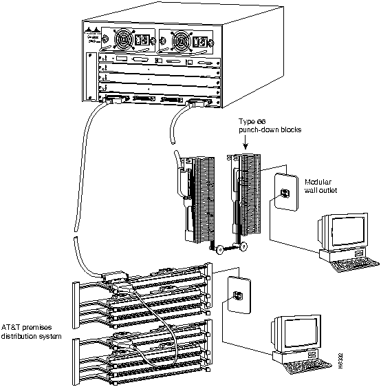
The following illustrations provide examples of commonly used wiring layouts for the Catalyst 5000 series.
Figure 113 : 180-Degree Male Telco Connector
(for WS-X5020 and WS-X5010 10BaseT modules)
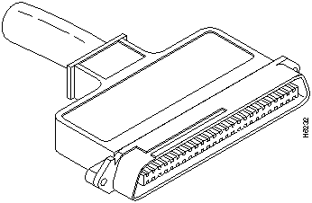
Figure 114 : 90-Degree Male Telco Connectors
(for WS-X5010 10BaseT modules only)
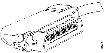
Figure 115 : Velcro Ties for Fastening 90-Degree Telco Connector Cables

Figure 116 : Catalyst 5000 With a 48-Port Group Switching 10BaseT Module
Using 180-Degree Telco Connectors
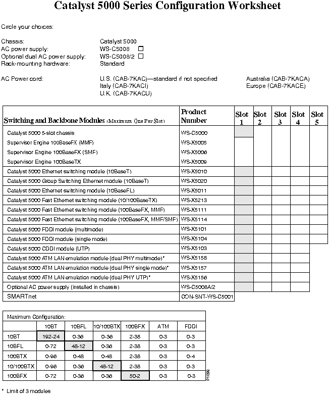
The Catalyst 5000 series system has many options. Use the Catalyst 5000 series Configuration Worksheet that follows to help you plan your order or to upgrade an existing system. One blank worksheet is provided, and you can make extra copies as needed.
The worksheet provides a chart to help you calculate maximum configurations. To use the chart, first select your primary interface choice from the left column (10BaseT, 10BaseFL,10/100BaseTX, or 100BaseFX). Then read across to determine configuration options. The bold boxes denote the maximum number of ports available for your primary interface choice.
For example, if you select 10BaseFL in the left column, the chart shows that the system can support a maximum of 48 to a minimum of 12 10BaseFL ports. If you choose the lowest end of the range (12 10BaseFL ports), you can look at the other columns of the same row to see how many of each of the other interface you can add. Notice that you have room left for 72 10BaseT ports, 38 100BaseTX ports, 36 10/100BaseTX ports, 36 100BaseFX ports, 3 ATM ports, or 3 FDDI ports, as follows:
![]()
On the other hand, if you choose the highest end of the range (48 10BaseFL ports), you have room left for 0 10BaseT ports, 2 100BaseTX ports, 0 10/100BaseTX ports, 0 100BaseFX ports, 0 ATM ports, or 0 FDDI ports. Note that the number range in the shaded boxes lists the highest number of ports first; this is to clarify the relationship to the number range in the other boxes, which range from low to high. As the number of your primary interface ports increases, the number of available ports on the other interface decreases.
|
|
Copyright 1988-1996 © Cisco Systems Inc.