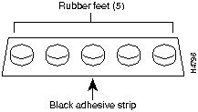
Step 3 Peel off one of the rubber feet from the black adhesive strip and place it adhesive-side down onto one of the five round recessed areas on the back of the chassis, as shown in Figure 2-2. Repeat this step to install the remaining four feet.
Figure 2-2 : Installing the Rubber Feet
Rack-Mounting the Chassis
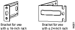
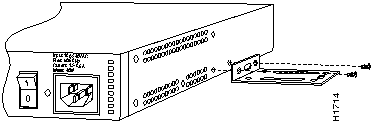
This section describes the procedures for rack-mounting the chassis. Your chassis ships with a bracket for use with a 19-inch rack or, if specified in your order, an optional, larger bracket for use with a 24-inch rack. The brackets are shown in Figure 2-3.
Figure 2-3 : Identifying the Brackets
Attaching the Brackets
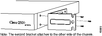
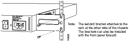
To install the chassis in a rack with the front panel forward, attach the brackets as shown in Figure 2-4 or Figure 2-5.
Figure 2-4 : 19-Inch Rack Installation---Front Panel Forward
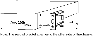
Figure 2-5 : 24-Inch Rack Installation---Front Panel Forward
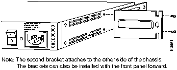
To install the chassis in a rack with the rear panel forward, attach the brackets as shown in Figure 2-6 or Figure 2-7.
Figure 2-6 : 19-Inch Rack Installation---Rear Panel Forward
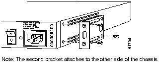
Figure 2-7 : 24-Inch Rack Installation---Rear Panel Forward
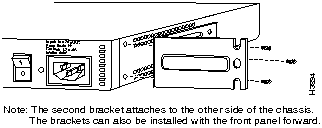
To install the chassis in a center-mount telco rack, attach the brackets as shown in Figure 2-8 or Figure 2-9.
Figure 2-8 : Telco 19-Inch Rack Installation---Rear Panel Forward
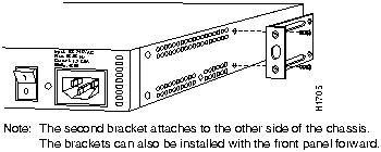
Figure 2-9 : Telco 24-Inch Rack Installation---Rear Panel Forward
Installing in a Rack
After the brackets are secured to the chassis, you can rack-mount the chassis. Using the screws you provide, attach the chassis to the rack as shown in Figure 2-10 or Figure 2-11.
Figure 2-10 : Attaching the Chassis to the 19-Inch Rack---Rear Panel Forward
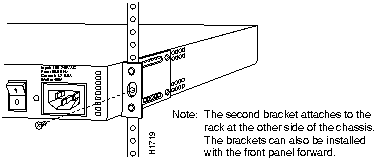
Figure 2-11 : Attaching the Chassis to the 24-Inch Rack---Rear Panel Forward
 Caution If you plan to place the router on a desk or table, do not place anything on top of the router that weighs in excess of 10 pounds (4.5 kg). Excessive weight on top could damage the chassis.
Wall-Mounting the Chassis
Use the smaller brackets, for use with a 19-inch rack, to wall-mount chassis. The smaller brackets will provide the most stable position for the chassis. To wall-mount the chassis, follow these steps:
Step 1 Attach the brackets as shown in Figure 2-12.
Figure 2-12 : Attaching the Wall-Mount Brackets
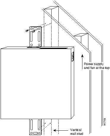
Step 2 Attach the chassis assembly to the wall as shown in Figure 2-13, using screws and anchors that you provide. We recommend the following:
- For the best support of the chassis and cables, attach the brackets so that the screws align with a vertical wall stud.
- For the best ventilation of the chassis, mount the chassis with the power supply and fan at the top.

Caution To prevent the chassis from pulling away from the wall when cables are attached, align the brackets and screws with a vertical wall stud. (See Figure 2-13.) To ensure adequate ventilation, make sure there is clearance between the router and the wall. Mount the router as shown in Figure 2-13, placing the chassis fan and power supply at the top.
Figure 2-13 : Wall-Mounting the Chassis
Preparing for External Connections
Following are the procedures for making external connections to the different router, access server, and hub models.
Connections for Router Models
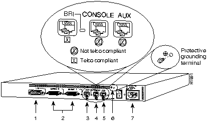
Figure 2-14 shows the rear panel of the single LAN router (the rear panel of the dual LAN router is similar), with the following connectors:
- Ethernet DB-15 (models 2501, 2503 [2503 shown], 2513, and 2514)
or Token Ring DB-9 (models 2502, 2504 [2502 shown], 2513, and 2515)
- Serial DB-60 (2 connectors---all models)
- BRI RJ-45 (models 2503, 2504, and 2516)

Caution To prevent damage to the system, connect the BRI cable to the BRI interface only and not to any other RJ-45 connector. The console, auxiliary, and BRI ports all use RJ-45 connectors.
- Console RJ-45
- Auxiliary RJ-45
- Protective grounding terminal (requires an M 3.5 thread-forming screw that is not included)
- AC power input
Figure 2-14 : Model 2503 Rear Panel
Connections for Hub Models
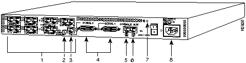
Figure 2-15 shows an example of the rear panel of a hub. This hub has 14 ports and the following connectors:
- One or two banks of Ethernet RJ-45
- MDI/MDI-X switch
- One BRI port
- Synchronous serial DB-60 (2 connectors---all models)
- Console RJ-45
- Auxiliary RJ-45
- Protective grounding terminal (requires an M 3.5 thread-forming screw that is not included)
- AC power input
Figure 2-15 : Hub (Model 2516) Rear Panel
Connections for Access Server Models
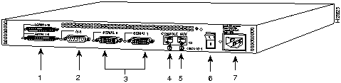
Figure 2-16 shows the rear panel of an access server with 16 ports and the following connectors:
- One or two 68-pin SCSI ports
- Ethernet DB-15 or Token Ring DB-9 (models 2510 and 2512 not shown)
- Synchronous serial DB-60 (2 connectors)
- Console RJ-45
- Auxiliary RJ-45
- Protective grounding terminal (requires an M 3.5 thread-forming screw that is not included)
- AC power input
Note If you are installing a model 2501, 2503, 2509, 2511, 2513, or 2514 and your Ethernet connection requires jackscrews, remove the slide-latch assembly from the AUI connector and attach the jackscrews provided.
Figure 2-16 : Access Server (Model 2511) Rear Panel
Making External Connections
Following is the procedure for connecting external cables to the router. If your router has an Ethernet port, begin at Step 1. If it has a Token Ring port, begin at Step 3. If it is a hub model, begin at Step 4.
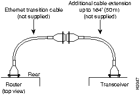
Step 1 Connect the Ethernet port to a transceiver as shown in Figure 2-17. If necessary, extend the Ethernet cable as shown in Figure 2-18.
- If your router has a Token Ring port, proceed to Step 3. If your router does not have a Token Ring port or if you are connecting a hub model, proceed to Step 4.
Step 2 If necessary, extend the Ethernet cable as shown in Figure 2-18. Otherwise, proceed to Step 3 if your router has a Token Ring port, or to Step 4 if your router does not have a Token Ring port or you are connecting a hub model.
Figure 2-17 : Ethernet Cable Connections
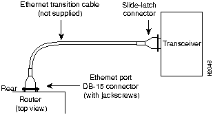
Figure 2-18 : Extending the Cable from the Ethernet Port
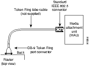
Step 3 Connect the Token Ring port to an MAU as shown in Figure 2-19.
Figure 2-19 : Token Ring Cable Connections
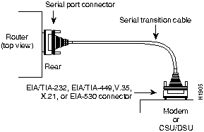
Step 4 Connect the serial ports to the modem or CSU/DSU as shown in Figure 2-20. Make certain to connect the 60-pin serial port connector as shown.
Figure 2-20 : Serial Cable Connections and DB-60 Connections
Step 5 On hub models, connect RJ-45 cables from the Ethernet ports to your external Ethernet devices. If you have a router model go to Step 7, and if you have a access server, omit this step and continue with Step 6.
Step 6 On access server models, connect modular SCSII-type breakout cables (available from Cisco Systems) to the 68-pin SCSI ports. If you have a 68-pin-to-RJ-45 breakout cable, use RJ-45-to-DB-25 adapters to connect the breakout cable to your serial devices. Or, if you have a 68-pin-to-DB-25 breakout cable, connect the DB-25 connector directly to your serial devices. Refer to the appendix "Cable Pinouts" for more information. Continue with Step 9.
 Caution Make sure that the SCSI connector on the breakout cable is securely connected to the SCSI connector on the access server. A short could occur which might damage your access server if the connection is disconnected.
Step 7 The Basic Rate Interface (BRI) port, a female RJ-45 connector on models 2503 and 2504 (see Figure 2-21), is located on the chassis rear panel between the serial 1 and console ports. On the Cisco 2516, the BRI port is located between the serial and Ethernet ports.
- On the Cisco 2516, set the MDI/MDI-X switch to MDI-X to configure the hub as a standalone hub. Set the MDI/MDI-X switch to MDI to configure Ethernet port 6 on the hub for connecting to another hub.
Step 8 Using the appropriate cable, connect the BRI port to the Integrated Services Digital Network (ISDN) through the NT1. The common carrier will provide the NT1 connection worldwide, except in North America, where the NT1 is customer owned.
Figure 2-21 : RJ-45 Female Connector---BRI, Console, and Auxiliary Ports

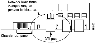
 Warning Network hazardous voltages are accessible in the BRI cable. If you detach the BRI cable, detach the end away from the router first to avoid possible electric shock. Network hazardous voltages are also accessible on the system card in the area of the BRI port (RJ-45 connector), regardless of whether power is turned OFF. (See Figure 2-22.)
Figure 2-22 : Network Hazardous Voltage Location
Step 9 Connect the asynchronous console and auxiliary ports as required for your method of configuration or if future configuration is expected.
- Depending on your terminal or modem connections, the console and auxiliary ports may require an RJ-45-to-DB-25 or RJ-45-to-DB-9 adapter (labeled "Terminal"). Your terminal should be configured for 9600 baud, 8 data bits, no parity, and 2 stop bits.

Caution To prevent damage to the system, make certain you connect the BRI cable to the BRI connector only and not to any other RJ-45 connector. The console, auxiliary, BRI, and hub ports all use RJ-45 connectors.
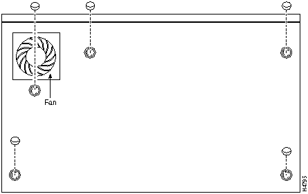
Step 10 Using an M 3.5 thread-forming screw (not included), attach a ground wire to the protective grounding terminal on the chassis rear panel, as required by your installation. (See Figure 2-14.)
Step 11 Connect the power cable between the router and the AC source.
Connecting the DC-Input Power Supply
This section describes the Cisco 2500 series direct current (DC) power supply specifications and wiring. This procedure covers the following information:
Read this entire section before wiring the power supply.
DC Power Specifications
The Cisco 2500 DC-input power supply is intended for use in DC operating environments. Table 2-1 lists the power supply specifications.
Table 2-1 : Cisco 2500 DC-Input Power Supply Specifications
| Power
|
40W, -40 to -72 VDC
|
| Wire gauge for power connections
|
14 AWG1
|
1 AWGAmerican Wire Gauge
Wiring the DC-Input Power Supply
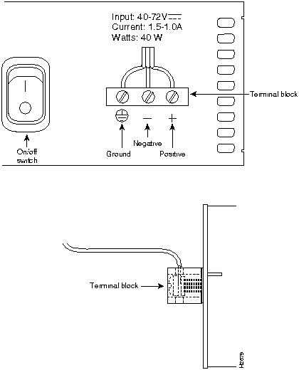
If you ordered a Cisco 2500 series router with a DC-input power supply, follow the directions in this section for proper wiring. Figure 2-23 shows the rear of the DC-input power supply (Model 2501-DC).
 Warning Before conducting any of the following procedures, ensure that power is removed from the DC circuit. To ensure that all power is OFF, locate the circuit breaker on the panel board that services the DC circuit, switch the circuit breaker to the OFF position, and tape the switch handle of the circuit breaker in the OFF position.
Note The installation must comply with all applicable codes.
Note This product is intended for installation in restricted access areas and is approved for use with copper conductors only.
Figure 2-23 : Cisco 2500 Series DC-Input Power Supply---Rear View
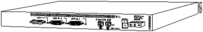
Figure 2-24 shows the Cisco 2500 DC-input power supply terminal block. Follow these procedures for wiring the terminal block.
Step 1 Attach the appropriate lugs at the wire end of the power supply cord.
Step 2 Wire the DC-input power supply to the terminal block as shown in Figure 2-24. The proper wiring sequence is ground to ground, positive to positive, and negative to negative.
 Caution Do not overtorque the terminal block captive thumbscrew or terminal block contact screws. The recommended torque is 8.2 ± 0.4 inch-lb.
 Caution Secure the wires so that they will not be disturbed by casual contact. For example, secure the wires to a rack frame using tie wraps.
Step 3 Remove the tape from the circuit breaker switch handle and restore power by moving the circuit breaker handle to the ON position.
Figure 2-24 : DC-Input Power Supply Connections
What to Do after Installing the Router Hardware
After you install the router hardware, the system is ready to be powered on and configured. For information on router software configuration, refer to the appropriate software publications.
Note To order UniverCD, Cisco's library of product information in CD-ROM format, or printed documentation, refer to Ordering Cisco Documentation, which is in your warranty pack.
Copyright 1988-1996 © Cisco Systems Inc.