
Table of Contents
Connecting the Cisco 4000 DC-Input Power Supply
Connecting the Cisco 4000 DC-Input Power Supply
Cisco Product Number: CISCO4000-DC
This publication describes the Cisco 4000 direct current (DC) power supply specifications and wiring. This publication contains the following sections:
Read this entire publication before wiring the power supply.
The Cisco 4000 DC-input power supply is intended for use in DC operating environments. Table 1 lists the power supply specifications.
Table 1 Cisco 4000 DC-Input Power Supply Specifications
| Power |
200W, 40 to 72 VDC |
| Wire gauge for power connections |
16 AWG(1) |
- (1)
- AWGAmerican Wire Gauge

Warning Before conducting any of the following procedures, ensure that power is removed from the DC circuit. To ensure that all power is OFF, locate the circuit breaker on the panel board that services the DC circuit, switch the circuit breaker to the OFF position, and tape the switch handle of the circuit breaker in the OFF position.
Note The installation must comply with the 1993 National Electric Code (NEC) and other applicable codes.
If you ordered a Cisco 4000 series router with a DC-input power supply, follow the directions in this section for proper wiring.
For identification purposes, Figure 1 shows the Cisco 4000 with DC-input power supply; Figure 2 shows the Cisco 4000 with an AC power supply.
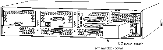
Figure 1 Cisco 4000 DC-Input Power Supply---Rear View
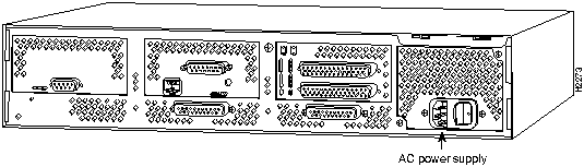
Figure 2 Cisco 4000 AC Power Supply---Rear View
Figure 3 shows the Cisco 4000 DC-input power supply terminal block. Follow these procedures for wiring the terminal block.
- Step 1 Feed the wires through the rubber grommet in the terminal block cover.
- Step 2 Attach the appropriate lugs at the wire end of the power supply cord.
- Step 3 Wire the DC-input power supply to the terminal block as shown in Figure 3. The proper wiring sequence is ground to ground, positive to positive, and negative to negative.
 Caution Do not overtorque the terminal block captive thumbscrew or terminal block contact screws. The recommended torque is 8.2 ± 0.4 inch-lb.
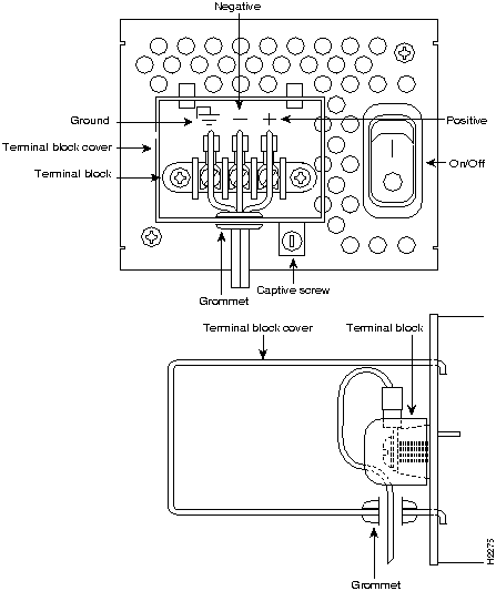
Figure 3 DC-Input Power Supply Connections

Warning After wiring the DC-input power supply, replace the terminal block cover and screw to ensure user safety.
- Step 4 Remove the tape from the circuit breaker switch handle and restore power by moving the circuit breaker handle to the ON position.
 Caution To avoid damaging the power supply when returning the chassis to the manufacturer (for example, in case of a failure), remove the power supply terminal block cover so that it will fit in the shipping container.
This completes the procedure for connecting the DC-input power supply.

Copyright 1988-1995
©
Cisco Systems Inc.