
Table of Contents
Configuring the Cisco 4000 Series Chassis
Configuring the Cisco 4000 Series Chassis
This chapter describes the tasks that should be completed before you connect a Cisco 4000 series router to your network. It contains the following sections:
You must open the chassis to gain access to the router's internal components---the network processor modules, boot ROMs, and jumpers.
Refer to the section "Required Tools and Equipment" in the chapter "Preparing to Install Cisco 4000 Series Routers" for the tools needed to complete the procedures in this chapter.
 Warning Before opening the chassis, disconnect the telephone-network cables to avoid contact with telephone-network voltages. (To see translated versions of this warning, refer to the appendix "Translated Safety Warnings.")
 Warning Do not work on the system or connect or disconnect cables during periods of lightning activity. (To see translated versions of this warning, refer to the appendix "Translated Safety Warnings.")
 Warning Do not touch the power supply when the power cord is connected. For systems with a power switch, line voltages are present within the power supply even when the power switch is off and the power cord is connected. For systems without a power switch, line voltages are present within the power supply when the power cord is connected. (To see translated versions of this warning, refer to the appendix "Translated Safety Warnings.")
 Warning Before working on a chassis or working near power supplies, unplug the power cord on AC units; disconnect the power at the circuit breaker on DC units. (To see translated versions of this warning, refer to the appendix "Translated Safety Warnings.")
Some Cisco 4000 series routers have a safety latch tab on the chassis that affects removing the component tray. (See Figure 3-1 and Figure 3-2.)
If you have a chassis with a safety latch tab, follow the procedure in the next section "Removing the Component Tray from a Chassis with a Safety Latch."
If you have a chassis without a safety latch tab, follow the procedure in the section "Removing the Component Tray from a Chassis without a Safety Latch."
Take the following steps to remove the component tray from a chassis with a safety latch:
Step 1 Turn OFF the system power.
Step 2 Put on your ESD-preventive wrist strap.
Step 3 Remove all network and power cables.
Step 4 Loosen the nonremovable chassis release screw on the rear panel of the chassis. (See Figure 3-1.)
Step 5 Pull on the handle located on the upper right corner of the chassis to slide the component tray out of the chassis shell until the safety latch catches. (See Figure 3-1.)
 Warning Before releasing the safety latch, support the component tray from underneath, either on your work surface or with your hands, to prevent personal injury. (See Figure 3-1.)
Figure 3-1 : Component Tray Removal for Chassis With a Safety Latch
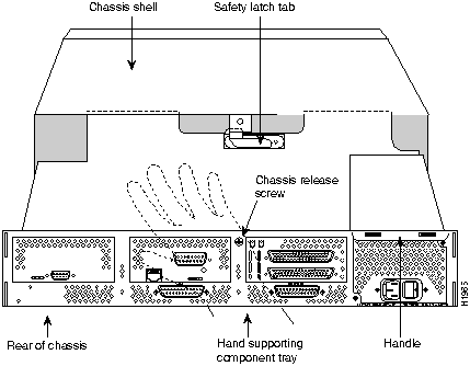
Step 6 Support the component tray with one hand, push down on the safety latch tab, and pull the component tray out the rest of the way.
Step 7 Set the component tray on your work surface.
Take the following steps to remove the component tray from a chassis without a safety latch:
Step 1 Turn OFF the system power.
Step 2 Put on your ESD-preventive wrist strap.
Step 3 Remove all network and power cables.
Step 4 Loosen the nonremovable chassis release screw on the rear panel of the chassis. (See Figure 3-2.)
Figure 3-2 : Component Tray Removal for Chassis Without a Safety Latch
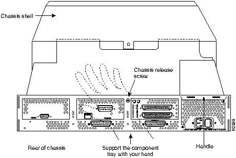
 Caution Support the component tray from underneath, either on your work surface or with your hands, to prevent it from falling. (To see translated versions of this warning, refer to the appendix "Translated Safety Warnings.")
Step 5 Pull on the handle located on the upper right corner of the chassis to slide the component tray out of the chassis shell while you support the component tray with one hand.
Step 6 Set the component tray on your work surface.
When you have removed the component tray from the router, you can remove or add network processor modules. If you are replacing shared memory single in-line memory modules (SIMMs), you must first remove the network processor modules.
 Caution Some network processor modules are secured to the rear of the chassis with two external screws. On modules with external rear mounting screws, including multimode Fiber-Distributed Data Interface (FDDI) modules, these screws must be removed before the module can be safely lifted out of the chassis.
Take the following steps to remove a network processor module:
Step 1 Orient the component tray as shown in Figure 3-3, then remove the module mounting screw from the top of the network processor module. Remove the two external rear mounting screws if the module has them. Set the screws aside.
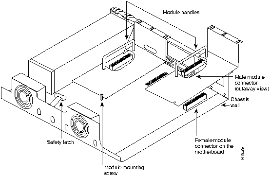
Step 2 Grasp the network processor module handle and pull it straight up to lift the module out of its connector. (See Figure 3-4.)
Step 3 Place the removed module on an ESD mat.
Figure 3-3 : Cisco 4000-M Component Tray---Typical of Cisco 4000 Series
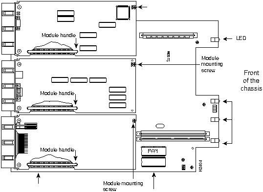
 Caution Do not wiggle the handle when handling the network processor module, and do not exert any side-to-side pressure because the handle might work loose and damage the network processor module.
Figure 3-4 : Network Processor Module Components
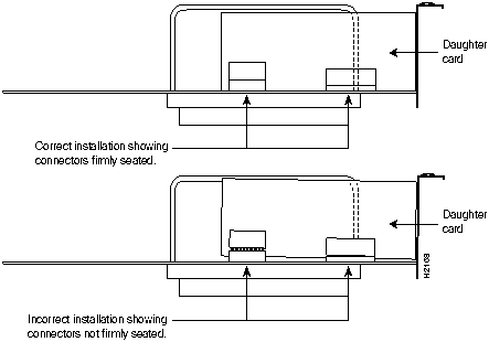
 Caution If any of the network processor module cards have daughter cards projecting at right angles to the module (see Figure 3-5), be careful not to cause the module to bow during installation; otherwise the daughter cards can become disconnected. If this happens, carefully reseat the daughter card connectors by handling the card by its edges without touching any of the components on the card.
Figure 3-5 : Network Processor Module Daughter Card Installation
Note See the appendix "Cabling Specifications for Cisco 4000 Series Routers" for network connection pinout information.
Take the following steps to install a network processor module:
Step 1 Hold the network processor module by its handle, align it with the grooves in the chassis (not shown) and over its connector, and push the module lightly against the chassis wall. (See Figure 3-4.)
Step 2 Push the network processor module gently into place without bending the connector pins, inserting the male connector into the female connector on the motherboard.
Step 3 Replace the module mounting screw in its place on the end of the network processor module. (See Figure 3-4.)
 Caution Do not overtighten the module mounting screw. The network processor module or the underlying motherboard could be damaged. The maximum screw torque is 7 inch-lb.
Step 4 Replace the external rear mounting screws, if used, to attach the module to the rear of the chassis.
Take the following steps to replace the component tray in the chassis shell:
Step 1 Reinsert the component tray into the chassis shell, pushing on the back of the tray while at the same time pressing on the chassis release screw with the thumb of your right hand. (See Figure 3-2.)
Step 2 Retighten the chassis release screw.
You can use optional rack-mount and wall-mount kits to install a Cisco 4000 series router in a standard 19-inch rack, a 19-inch telco rack, or on a wall. The procedures for the different installation options involve removing the front panel and component tray from the chassis, fastening mounting brackets to the chassis, and then installing the empty chassis in position. You then reinsert the component tray and replace the front panel.
The optional rack-mount and wall-mount kits ship with their own set of installation instructions. If you are planning to rack-mount or wall-mount the router, do so before making the network and power connections.
Copyright 1988-1996 © Cisco Systems Inc.
![]()
![]()
![]()
![]()
![]()


![]()
![]()

![]()

![]()

![]()
![]()
![]()
![]()
![]()
![]()
![]()
![]()
![]()