|
|
Troubleshooting the Initial Hardware Configuration
Cisco 4000 series routers are extensively tested before leaving the factory. However, if there are problems starting up your system, refer to this appendix to help identify the cause.
This appendix contains the following sections:
Use the information in this appendix to help isolate problems or rule out the router as the source of the problem. If you cannot locate the source of your problem, contact a service representative for information on how to proceed. Before you call, have the following information ready:
This section explains how to recover the following types of passwords:
The key to recovering a lost enable password is to set the configuration register so that the contents of NVRAM are ignored (0x142), which allows you to see your password. The enable secret password is encrypted and cannot be recovered; it must be replaced. The enable and console passwords might be encrypted or clear text.
The outline of the steps in the password recovery procedure follows:
Take the following steps to recover or replace a lost enable, enable secret, or console login password:
The key to problem solving in this system is to try to isolate the problem to a specific subsystem. By comparing what the system is doing to what it should be doing, the task of isolating a problem is greatly simplified.
When problem solving, consider the following subsystems of the router:
Check the following items to help isolate the problem:
Check for the following symptoms to help isolate the problem:
If the router is operating at an abnormally high temperature, the following message will be displayed on the console screen:
Typical causes of an abnormally high system temperature are as follows:
The LEDs on the front panel of the router enable you to determine system performance and operation at a glance. This section contains information about the LEDs.
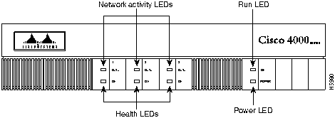
Figure A-1 shows the network activity, health, run, and power LEDs on the front panel of the router.
Figure A-1 : Cisco 4000 Series---Front Panel LEDs On the front panel, the three LEDs labeled OK correspond to the three network processor modules, if present, and show their status. The upper LEDs labeled DATA, when blinking, indicate network activity on the interfaces of each module.
When on, the LED labeled POWER indicates that the system card's power is on, and the OK LED above indicates that the processor is working.
The network processor module LEDs are all visible through cutouts in the rear of the chassis.
The LEDs on the single-port Ethernet network processor module are labeled as shown in Figure A-2. (Also see Figure 4-4.)
Figure A-2 : Single-Port Ethernet Network Processor Module LEDs The LEDs on the dual-port Ethernet network processor module are labeled as shown in Figure A-3. (Also see Figure 4-8.)
Figure A-3 : Dual-Port Ethernet Network Processor Module LEDs The LEDs on the six-port Ethernet network processor module are labeled as shown in Figure A-4. (Also see Figure 4-9.)
Figure A-4 : Six-Port Ethernet Network Processor Module LEDs When the AUI LED is on, none of the other LEDs on the network processor module will be on. The other LEDs are meaningful only when you use 10BaseT, and you have a link.
The LEDs on Ethernet network processor modules are explained in Table A-1.
Table A-1 : Ethernet Network Processor Module LEDs
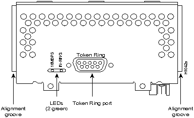
The two LEDs in the Token Ring network processor module are labeled 16M and IN-RING. (See Figure A-5.)
The 16M LED indicates ring speed. When on, it indicates a ring speed of 16 Mbps; when off, it indicates a ring speed of 4 Mbps.
The in-ring LED, when on, indicates that the network processor module is inserted into the ring. If the LED is off, the network processor module is not inserted into the ring.
Figure A-5 : Token Ring Module Network Connector
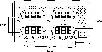
The four-port serial network processor module has six LEDs per port. (See Figure A-6 and Table A-2.) The functions of the LEDs on the four-port serial module are the same as the functions on the G.703/G.704 module and are different from the functions of the LEDs on the dual-port serial module.
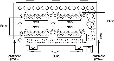
The G.703/G.704 network processor module has six LEDs per port. (See Figure A-7 and Table A-2.) The functions of the LEDs on the G.703/G.704 module are the same as the function on the four-port serial module and are different from the functions of the LEDs on the dual-port serial module.
Figure A-6 : Four-Port Serial Network Processor Module Ports Figure A-7 : G.703/G.704 Serial Network Processor Module Ports (DB-15) Table A-2 : Four Port Serial Network Processor Module LEDs
TC, RC, TD, and RD are on only when the associated line is changing state; if a line is stuck high or low, the LED is off.
The CN LED on whenever activity is detected on any of the following circuits: data set ready (DSR), data terminal ready (DTR), data carrier detect (DCD), request to send (RTS), and clear to send (CTS).
TD is always associated with the data that is driven by the DTE port, regardless whether the port on the module is a DTE port or a DCE port. This means that TD reflects output data when the port is a DTE port and input data when the port is a DCE port. RD is controlled in a similar way. TC and RC are always associated with the clocks that are driven by the DCE: outputs for a DCE port and inputs for a DTE port.
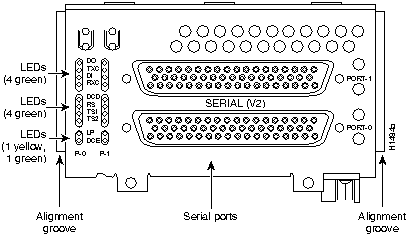
The dual-port serial network processor module has two columns of LEDs. As viewed from the front (see Figure A-8), the left column is labeled P-0 (for port 0), and the right column is labeled P1 (for port 1). There are ten LEDs per port. Serial network processor modules can be configured for either DTE or DCE.
Figure A-8 : Dual-Port Serial Network Processor Module When DCE cables are used and when the port is configured with the clockrate command as a DCE port, the DCE LED will go on. (See Figure A-8.) (For more information about the clockrate command, see the Cisco IOS configuration guides and command references.)
The convention used in this publication to indicate corresponding signals for DTE and DCE is to list DTE first. For example, Figure A-8 shows the top LED, D0, indicates transmit data (TXD) in DTE mode or receive data (RXD) in DCE mode.
The dual-port serial network processor module LEDs are explained in Table A-3.
Table A-3 : Dual-Port Serial Network Processor Module LEDs
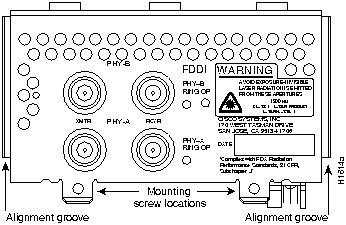
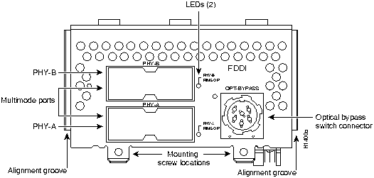
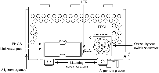
Dual-attachment FDDI network processor modules have one LED per port, which is located adjacent to the corresponding port on the module panel (see Figure A-9 and Figure A-10). Single-attachment modules have one LED, which is adjacent to the single port on the module panel. (See Figure A-11.)
Figure A-9 : Dual-Attachment Single-Mode FDDI Network Processor Module---End View Figure A-10 : Dual-Attachment Multimode FDDI Network Processor Module---End View Figure A-11 : Single-Attachment Multimode FDDI Module---End View When on, a module LED indicates a ring up condition. Dual-attachment FDDI module LEDs indicate which PHY on the network processor module is inserted into the ring; if a PHY is not actively inserted into the ring, the LED is off. On a single-attachment module, the LED indicates ring up when it is on; when the LED is off, it indicates that the module is not inserted into a ring.
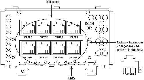
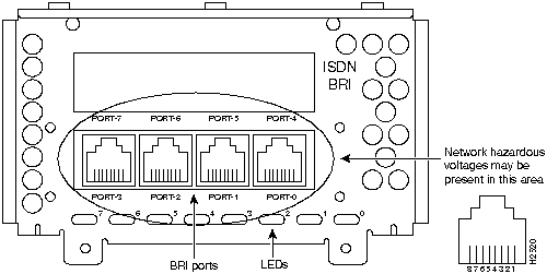
When on, the multiport BRI network processor module status LEDs indicate a Layer 1 connection on the corresponding port. When off, the LEDs indicate that the link is not established on the corresponding port.
Figure A-12 : Eight-Port BRI Network Processor Module Figure A-13 : Four-Port BRI Network Processor Module
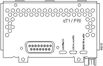
The three LEDs on the CT1/PRI network processor module are labeled LOOPBACK, LOCAL ALARM, and REMOTE ALARM. (See Figure A-14.)
Figure A-14 : Channelized T1 Network Interface Processor The three LEDs on the CT1/PRI network processor module front panel are explained in Table A-4.
Table A-4 : CT1/PRI Network Processor Module LEDs
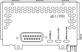
The three LEDs on the CE1/PRI network processor module are labeled LOOPBACK, LOCAL ALARM, and REMOTE ALARM. (See Figure A-15.)
Figure A-15 : CE1/PRI Network Processor Module The three LEDs on the CE1/PRI network processor module front panel are explained in Table A-5.
Table A-5 : CE1/PRI Network Processor Module LEDs
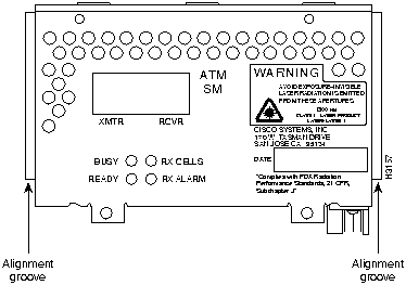
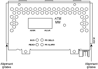
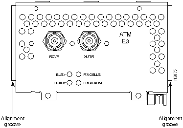
The four LEDs on the ATM network processor module are labeled BUSY, READY, RX CELLS, and RX ALARM. (See Figure A-16, Figure A-17, and Figure A-18.)
Figure A-16 : ATM Network Processor Module with STS-3c/STM-1 Single-Mode PLIM Figure A-17 : ATM Network Processor Module with STS-3c/STM-1 Multimode PLIM Figure A-18 : ATM Network Processor Module With E3/DS-3 PLIM The four LEDs on the ATM network processor module front panel are explained in Table A-6.
Table A-6 : ATM Network Processor Module LEDs
Copyright 1988-1996 © Cisco Systems Inc.
o/r 0x142
rommon 1 >
confreg
Configuration Summary
enabled are:

console baud: 9600

boot: image specified by the boot system command

  or default to: cisco2-RSP
do you wish to change the configuration? y/n [n]: y

enable "diagnostic mode"? y/n {n]:

enable "use net in IP bcast address"? y/n [n]:

enable "load rom after netboot fails"? y/n [n]:

enable "use all zero broadcast"? y/n [n]:

enable "break/abort has effect"? y/n [n]:

enable "ignore system config info"? y/n [n]: y

change console baud rate? y/n [n]:

change boot characteristics? y/n [n]:
Configuration Summary
enabled are:

console baud: 9600

ignore system config info

boot: image specified by the boot system command

  or default to: cisco2-RSP
do you wish to change the configuration? y/n [n]:
You must reset or power cycle for the new config to take effect
>
i
rommon 2 >
reset
--- System Configuration Dialog --
Press RETURN to get started!
Router>
Router# show startup-config
enable secret 5 $1$ORPP$s9syZt4uKn3SnpuLDrhuei

enable password 23skiddoo

.

.

line con 0

 password onramp
![]()
Router# configure memory
Router# configure terminal
Router (config)# enable secret newpassword1

Router (config)# enable password newpassword2

Router (config)# line con 0

Router (config-line)# password newpassword3
Router(config-line)# interface ethernet 0

Router(config)# no shutdown
Router# config-register 0x2102

Router#
![]()
Router# copy running-config startup-config

Building configuration

[OK]

Router#
Router#
reload

Proceed with reload? [confirm] Problem Solving
Troubleshooting the Power and Cooling Systems
Troubleshooting the Network Processor Modules and Cables
Environmental Reporting Features
%SYS-1-OVERTEMP: System detected OVERTEMPERATURE condition. Please
resolve cooling problem immediately!
Reading Front-Panel LEDs
System LED Operation
Reading Network Processor Module LEDs
Ethernet Network Processor Module LEDs
![]()


LEDs
Indication
TX (transmit)
System is transmitting data
RX (receive)
System is receiving data
AUI (attachment unit interface)
AUI connection is selected
LNK (link)
10BaseT is selected and the link is available
POL (polarity)
Polarity has been switched to correct for defective polarity
Token Ring Network Processor Module LEDs
![]()
Four-Port Serial Module LEDs
G.703/G.704 Module LEDs
LEDs
LED Colors
Indication
LP
Yellow
Loop
CN
Green
Connect (DSR, DTR, DCD, RTS, CTS)
TD
Green
Transmit Data
TC
Green
Transmit Clock
RD
Green
Receive Data
RC
Green
Receive Clock
Dual-Port Serial Network Processor Module LEDs
LEDs
Indication (DTE/DCE)
DO
Data Out (TXD/RXD)
TXC
Transmit Clock
DI
Data In (RXD/TXD)
RXC
Receive Clock
DCD
Data Carrier Detect
RS
Receive Signaling
TS1
Transmit Signaling
TS2
Transmit Signaling
LP
Loop
DCE
On if the serial interface is DCE
FDDI Network Processor Module LEDs
BRI Network Processor Module LEDs
CT1/PRI Network Processor Module LEDs
LEDs
Indication (DTE/DCE)
Loopback
Controller loopback
Local alarm
Loss of signal, loss of frame, or unavailability due to excessive errors
Remote alarm
Remote end in local alarm
CE1/PRI Network Processor Module LEDs
LEDs
Indication (DTE/DCE)
Loopback
Controller loopback
Local alarm
Loss of signal, loss of frame, or unavailability due to excessive errors
Remote alarm
Remote end in local alarm
ATM Network Processor Module LEDs
LEDs
Indication
Busy
Not applicable in normal use
Ready
When on, configuration is complete and module is ready for use
RX cells
The module is receiving traffic (cells)
RX alarm
Loss of signal or remote alarm
![]()
![]()
![]()
![]()
![]()
![]()
![]()
![]()