|
|

Configuring for ISDN and Analog Calls
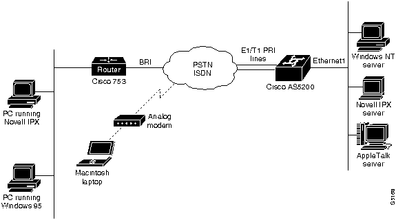
This chapter explains how to configure the access server to accept ISDN and analog calls so that remote clients can access network resources. It also includes configuration information for the access server to accept dial in calls from the Cisco 753 and Cisco 1004. Figure 3-1 shows a typical dial in scenario.
If you are configuring a Cisco 753 or Cisco 1004 router to dial in to an access server and need configuration information, you can receive a fax-back document from Cisco's Technical Assistance Center at 800 553-2447 or 408 526-7209 or call directly into the fax-on-demand service at 415 596-4408.
To configure the access server to accept calls from routers such as the Cisco 753 and Cisco 1004, follow the steps outlined in the these sections:
A comprehensive configuration example is provided at the end of this chapter. Commands that are not specific to remote dial in and dial out access for the listed devices are described in previous chapters.
Figure 3-1 : Remote Clients Dialing in to the AS5200 to Access Network Resources
The configuration information in this chapter builds on preceding configurations from previous chapters and assumes you understand group asynchronous interfaces, basic asynchronous modem configuration, and autoselect. Users dialing in must also be running one of the following applications:
For each of the following configuration examples, dialin users are assumed to belong to one subnet. In this way, all the remote clients appear to belong to one Ethernet segment from the access server's perspective.
Enabling Remote IP Users to Dial in to IP Networks
This section includes the base configuration to enable IP clients to access network resources by dialing through the access server. Configure remote IP dialin before you enter any commands for IPX or AppleTalk, even if you are setting up an IPX- or AppleTalk-only network.
Enter the following access server configuration sequentially, first entering the commands featured in the "Entering Configuration Mode" section (enter your own addresses, host names, and passwords where appropriate).
To enter configuration mode, follow these steps:
Proceed with the "Configuring Security" section.
To set up a base security and local database, enter the following commands starting in global configuration mode:
Proceed with the "Configuring the ISDN Switch Type" section.
Configuring the ISDN Switch Type
To configure the ISDN switch servicing your T1 PRI or E1 PRI lines, enter the following command in global configuration mode. The switch type can be obtained from your telephone service provider:
Proceed with the "Configuring the Controllers" section.
Your access server is configured with a Dual T1 PRI card or a Dual E1 PRI card. Use one of the following procedures to configure your access server.
To configure the T1 controllers, which accept incoming calls and send outgoing calls through ISDN PRI lines, follow these steps:
Proceed with the "Configuring the ISDN D Channel Serial Interfaces" section.
To configure the E1 controllers, which accept and send incoming and outgoing calls through ISDN PRI lines, follow these steps:
Proceed with the "Configuring the ISDN D Channel Serial Interfaces" section.
Configuring the ISDN D Channel Serial Interfaces
After you configure the controller, two corresponding D channel serial interfaces are instantly created. For Dual T1 PRI cards, serial interface 0:23 is the D channel for the T0 controller, and serial interface 1:23 is the D channel for T1 controller. For Dual E1 PRI cards, serial interface 0:15 is the D channel for the E0 controller, and serial interface 1:15 is the D channel for E1 controller.
You must configure each serial interface to receive incoming and send outgoing modem signaling.
To configure the ISDN D channel serial interfaces, follow these steps:
Continue on to the "Creating Interfaces for Asynchronous and ISDN Dialin Services" section.
Creating Interfaces for Asynchronous and ISDN Dialin Services
This section describes how to configure the access server interfaces that enable dial in clients to make remote asynchronous and ISDN connections to the access server.
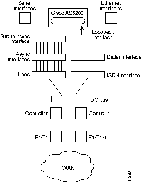
To configure remote services, you must configure three interrelated interfaces on the access server. The loopback interface makes the network appear as if the dialin users exist on one Ethernet segment. The loopback interface has the following four types of neighboring interfaces used for dialin operations: ISDN interface, dialer interface, group asynchronous interface, and asynchronous interface. Figure 3-2 shows an internal view of the components used to process incoming ISDN and analog calls on an access server.
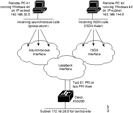
Figure 3-2 : Internal View of Access Server Call Processing Components All dial in users exist on one dialin subnet. Remote asynchronous users dial in through the group asynchronous interface to the access server. Remote ISDN users dial in through the ISDN dialer interface to the access server. Figure 3-3 shows an external view of how remote users dial in to the access server.
Figure 3-3 : External View of Access Server Call Processing Components Configuring the Loopback and Ethernet Interfaces
The loopback 0 interface is a virtual IP interface carrying all the dialin users, and it exists only in the access server. You assign an IP network number to the loopback interface, then let each asynchronous interface borrow this network number.
To configure the loopback and Ethernet interface, follow these steps:
Proceed with the "Creating the Group Asynchronous Interface" section.
Creating the Group Asynchronous Interface
A group asynchronous interface is the parent interface that applies protocol characteristics to specified asynchronous ports. To configure the group asynchronous interface, follow these steps:
Proceed with the "Configuring the ISDN Dialer Interface" section.
Configuring the ISDN Dialer Interface
The ISDN dialer interface is the parent interface that holds the central protocol characteristics for the two ISDN D channels that are part of dialer rotary-group 1. The previous section "Configuring the ISDN D Channel Serial Interfaces" described how to configure the ISDN D channels on serial interfaces.
To configure the ISDN dialer interface, follow these steps:
Proceed with the "Configuring Modem Lines" section.
To configure the modem lines, use the following series of commands:
Proceed with the "Defining a Routing Protocol and Domain Name" section.
Defining a Routing Protocol and Domain Name
To complete the configuration, you must define a routing protocol and a domain name. You also can specify a domain name server to resolve host names and IP addresses.
Proceed with the "Enabling DNS and NBNS Services for PPP Users" section.
Enabling DNS and NBNS Services for PPP Users
Dialin clients using PPP and applications such as CiscoRemote, Windows NT, and Windows '95 need domain name service (DNS) and NetBIOS Name Service (NBNS) address information as described in RFC 1877. Use the following procedure to enter parameters to enable Telnet users to gather this information transparently as part of the PPP negotiation:
Configuring the Access Server to Accept Dialin Calls from the Cisco 753 and Cisco 1004
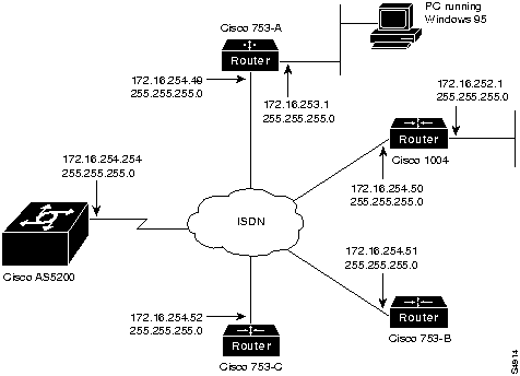
This section explains how to enable a remote ISDN user to dial in to an access server through a Cisco 753 or Cisco 1004 on an IP network. See Figure 3-4.
Figure 3-4 : Sample Addressing Scheme for ISDN Routers Dialing in to the Access Server Enabling Remote IPX Users to Dial in to IPX Networks
To enable IPX clients to access network resources by dialing through the access server over ISDN, complete the following tasks (enter your own addresses where appropriate).
Enabling Macintosh Users to Access AppleTalk Resources
To enable Macintosh clients to access network resources by dialing through the access server over ISDN, follow these steps (enter your own addresses where appropriate):
Comprehensive Configuration for the Access Server
This section includes a complete start up configuration for the access server. This configuration includes a comprehensive setup for dialing in to IP, IPX, and AppleTalk networks.
The following configuration establishes a base security and local database:
The following global configuration command sets the ISDN switch type:
The following commands configure the appropriate interfaces for IP dial in:
The following example configures modem lines 1 to 48:
The following commands configure enhanced IGRP:
Configuring a Dialin Pool, Domain Name, DNS Server, and NBNS Server
The following commands configure a range of IP addresses in an IP address pool, a domain name, and name servers:
The following commands enable IPX dial in:
The following commands enable users running PPP applications to dial in to an AppleTalk network:
Copyright 1988-1996 © Cisco Systems Inc.
Would you like to enter the initial dialog? [yes]:
no
Router>
enable
Router#
Router#
configure terminal
Enter configuration commands, one per line. End with CNTL/Z.
Router(config)#
hostname as5200
as5200(config)#
enable password irongate
as5200(config)# aaa new-model
as5200(config)# aaa authentication login default local
as5200(config)# aaa authentication login console none
as5200(config)# aaa authentication ppp default if-needed local
as5200(config)# username jojackso password <password>
as5200(config)# username wmays password <password>
as5200(config)# username bruth password <password>
as5200(config)# username hwilliam password <password>
as5200(config)# isdn switch-type primary-5ess
as5200(config)#
controller T1 0
as5200(config-controller)#
as5200(config-controller)#
framing esf
as5200(config-controller)#
linecode b8zs
as5200(config-controller)#
clock source line primary
as5200(config-controller)#
pri-group timeslots 1-24
as5200(config-controller)#
exit
as5200(config)#
as5200(config-controller)#
cas-group 1 timeslots 1-24 type e&m-fgb
as5200(config-controller)#
exit
as5200(config)#
as5200(config-controller)#
channel-group 1 timeslots 1-24
as5200(config-controller)#
exit
as5200(config)#
as5200(config)#
controller T1 1
as5200(config-controller)#
framing esf
as5200(config-controller)#
linecode b8zs
as5200(config-controller)#
clock source line secondary
as5200(config-controller)#
pri-group timeslots 1-24
as5200(config-controller)#
exit
as5200(config)#
as5200(config)#
controller E1 0
as5200(config-controller)#
as5200(config-controller)#
framing crc4
as5200(config-controller)#
linecode hdb3
as5200(config-controller)#
clock source line primary
as5200(config-controller)#
pri-group timeslots 1-31
as5200(config-controller)#
exit
as5200(config)#
as5200(config-controller)#
channel-group 1 timeslots 1-31
as5200(config-controller)#
exit
as5200(config)#
as5200(config)#
controller E1 1
as5200(config-controller)#
framing crc4
as5200(config-controller)#
linecode hdb3
as5200(config-controller)#
clock source line secondary
as5200(config-controller)#
pri-group timeslots 1-31
as5200(config-controller)#
exit
as5200(config)#
as5200(config)#
interface Serial 0:23
or, for E1 PRI
as5200(config)#
interface Serial 0:15
as5200(config-if)#
as5200(config-if)#
isdn incoming-voice modem
as5200(config-if)#
dialer rotary-group 1
as5200(config-if)#
exit
as5200(config-if)#
interface Serial 1:23
or, for E1 PRI
as5200(config-if)#
interface Serial 1:15
as5200(config-if)#
isdn incoming-voice modem
as5200(config-if)#
dialer rotary-group 1
as5200(config-if)#
exit
as5200(config)#
as5200(config)#
interface loopback 0
%LINEPROTO-5-UPDOWN: Line protocol on Interface Loopback0, changed state to up
as5200(config-if)#
as5200(config-if)#
ip address 172.16.254.254 255.255.255.0
as5200(config-if)#
exit
as5200(config)#
as5200(config)#
interface Ethernet 0
as5200(config-if)#
ip address 172.16.1.1 255.255.255.0
as5200(config-if)#
exit
as5200(config)#
as5200(config)#
interface Group-Async 1
as5200(config-if)#
ip unnumbered Loopback 0
as5200(config-if)#
ip tcp header-compression passive
as5200(config-if)#
encapsulation ppp
as5200(config-if)#
async mode interactive
as5200(config-if)#
ppp authentication chap pap
as5200(config-if)#
group-range 1 48
or, for E1 PRI
as5200(config-if)#
group-range 1 60
Building configuration...
as5200(config-if)#
as5200(config-if)#
peer default ip address pool default
as5200(config-if)#
dialer-group 1
as5200(config-if)#
exit
as5200(config)#
ip local pool default 172.16.254.1 172.16.254.48
or, for E1 PRI
as5200(config)#
ip local pool default 172.16.254.1 172.16.254.60
as5200(config)#
as5200(config)#
interface Dialer 1
as5200(config-if)#
ip unnumbered Loopback 0
as5200(config-if)#
encapsulation ppp
as5200(config-if)#
peer default ip address pool default
as5200(config-if)#
dialer in-band
as5200(config-if)#
dialer-group 1
as5200(config-if)#
dialer idle-timeout 3600
as5200(config-if)#
ppp multilink
as5200(config-if)#
ppp authentication chap pap
as5200(config-if)#
exit
as5200(config)#
dialer-list 1 protocol ip permit
as5200(config)# line 1 48
! or, for E1 PRI
as5200(config)# line 1 60
as5200(config-line)# modem InOut
as5200(config-line)# modem autoconfigure type microcom_hdms
as5200(config-line)# transport input all
as5200(config-line)# stopbits 1
as5200(config-line)# rxspeed 57600 (or rxspeed 64000 for E1 PRI)
as5200(config-line)# txspeed 57600 (or txspeed 64000 for E1 PRI)
as5200(config-line)# flowcontrol hardware
as5200(config-line)# login local
as5200(config-line)# autoselect during-login
as5200(config-line)# autoselect ppp
as5200(config)# router eigrp 202
as5200(config-router)# network 172.16.0.0
as5200(config-router)# exit
as5200(config)# ip domain-name cisco.com
as5200(config)# ip name-server 172.16.99.99
as5200(config)#
async-bootp dns-server 172.16.10.100 172.16.39.67
as5200(config)#
async-bootp nbns-server 172.16.200.200 172.16.201.200
as5200(config)#
exit
as5200#
copy running-config startup-config
#########[OK]
as5200#
If you are configuring the Cisco 753 or Cisco 1004 and need configuration information, you can receive a fax-back document from Cisco's Technical Assistance Center at 800 553-2447 or 408 526-7209 or call directly into the fax-on-demand service at 415 596-4408.
as5200(config)#
interface dialer 1
as5200(config-if)#
dialer map ip 172.16.254.49 name 753-A
as5200(config-if)#
dialer map ip 172.16.254.49 name 753-A speed 56
as5200(config-if)#
dialer map ip 172.16.254.50 name 1004
as5200(config-if)#
exit
as5200(config)#
as5200(config)#
username 753-A password letmein
as5200(config)#
ip route 172.16.253.1 255.255.255.0 172.16.254.49
![]()
as5200(config)#
username 1004 password openup
as5200(config)#
ip route 172.16.252.1 255.255.255.0 172.16.253.50
as5200(config)# exit
as5200#
copy running-config startup-config
#########[OK]
as5200#
as5200(config)#
ipx routing
as5200(config)#
interface loopback 0
as5200(config-if)#
ipx network FEFEFE
as5200(config-if)#
exit
as5200(config)#
interface ethernet 0
as5200(config-if)#
ipx network 123ABCD encapsulation SAP
as5200(config-if)#
exit
as5200(config)#
interface group-Async 1
as5200(config-if)#
group-range 1 48
or, for E1 PRI
as5200(config-if)#
group-range 1 60
Building configuration...
as5200(config-if)#
ipx ppp-client Loopback 0
as5200(config-if)#
exit
as5200(config)#
interface dialer 1
as5200(config-if)#
ipx unnumbered loopback 0
as5200(config-if)#
dialer map ipx FEFEFE.0000.0c00.1234 name jordan
as5200(config-if)#
dialer map ipx FEFEFE.0000.0c00.4567 name rodman
as5200(config-if)#
dialer map ipx FEFEFE.0000.0c00.89AB name kemp
as5200(config-if)#
exit
as5200(config)#
dialer-list 1 protocol ipx permit
as5200(config)# exit
as5200#
copy running-config startup-config
#########[OK]
as5200#
as5200# configure terminal
Enter configuration commands, one per line. End with CNTL/Z.
as5200(config)#
appletalk routing
as5200(config)#
appletalk virtual-net 2 ATCP Zone
as5200(config)#
appletalk cable-range 1-1 1.120
as5200(config-if)#
appletalk zone Ethernet
as5200(config-if)#
exit
as5200(config)#
exit
as5200#
copy running-config startup-config
#########[OK]
as5200#
aaa new-model
aaa authentication login default local
aaa authentication login console none
aaa authentication ppp default if-needed local
username jojackso password
username wmays password
username bruth password
username hwilliam password
!
isdn switch-type primary-5ess
! T1 PRI controller configuration

controller T1 0
 framing esf
 linecode b8zs
 clock source line primary
 pri-group timeslots 1-24
!
controller T1 1
 framing esf
 linecode b8zs
 clock source line secondary
 pri-group timeslots 1-24

or

! E1 PRI controller configuration

controller E1 0
 framing crc4
 linecode hdb3
 clock source line primary
 pri-group timeslots 1-31
!
controller E1 1
 framing crc4
 linecode hdb3
 clock source line secondary
 pri-group timeslots 1-31


!
interface Serial0:23
! or, for E1 PRI
interface Serial0:30
 isdn incoming-voice modem
 dialer rotary-group 1
!
interface Serial1:23
! or, for E1 PRI
interface Serial1:30

 isdn incoming-voice modem
 dialer rotary-group 1
!
interface Loopback0
 ip address 172.16.254.254 255.255.255.0
!
interface Ethernet0
 ip address 172.16.1.1 255.255.255.0
!
interface Group-Async1
 ip unnumbered Loopback0
 ip tcp header-compression passive
 encapsulation ppp
 async mode interactive
 peer default ip address pool default
 dialer-group 1
 ppp authentication chap pap default
 group-range 1 48
! or, for E1 PRI
 group-range 1 60
!
interface Dialer1
 ip unnumbered Loopback0
 encapsulation ppp
 peer default ip address pool default
 ip local pool default 172.16.254.1 172.16.254.48
! or, for E1 PRI
 ip local pool default 172.16.254.1 172.16.254.60
 dialer in-band
 dialer-group 1
 dialer idle-timeout 3600
 ppp multilink
 ppp authentication chap pap default
line 1 48
! or, for E1 PRI
line 1 60
 autoselect during-login
 autoselect pppmodem InOut
 modem autoconfigure type microcom_hdms

 transport input all
 stopbits 1
 rxspeed 57600 (64000 for E1 PRI)
 txspeed 57600 (64000 for E1 PRI)
 flowcontrol hardware
 login local
as5200 eigrp 202
 network 172.16.0.0
ip domain-name cisco.com
ip name-server 172.16.99.99
!
async-bootp dns-server 172.16.10.100 172.16.39.67
async-bootp nbns-server 172.16.200.200 172.16.201.200
dialer-list 1 protocol ip permit
ipx routing 0060.3ef1.6f74

interface Loopback0
 ipx network FEFEFE

interface Ethernet 0
 ipx network 123ABCD encapsulation SAP

interface Group-Async1
 group-range 1 48
! or, for E1 PRI
 group-range 1 60

 ipx ppp-client Loopback0

interface Dialer1
 ipx unnumbered loopback 0
 dialer map ipx FEFEFE.0000.0c00.1234 name stock
 dialer map ipx FEFEFE.0000.0c00.4567 name john
 dialer map ipx FEFEFE.0000.0c00.89AB name cisco
 dialer-list 1 protocol ipx permit
appletalk routing
appletalk virtual-net 2 ATCP Zone
appletalk cable-range 1-1 1.120
appletalk zone Ethernet
![]()
![]()
![]()
![]()
![]()
![]()
![]()
![]()