|
|

Catalyst 5000 Series CDDI and FDDI Module Configuration Note
Product Numbers: WS-X5101, WS-X5104, and WS-X5103
This document contains instructions for installing the Catalyst 500 series CDDI and FDDI modules. It also contains procedures for configuring the modules once they are installed. Configuration examples are also provided. For a complete description of commands used to configure and maintain the Catalyst 5000 series switch, refer to the Catalyst 5000 Series Configuration Guide and Command Reference. For complete hardware configuration and maintenance procedures, refer to the Catalyst 5000 Series Installation Guide. These documents are available on the Cisco Connection Documentation, Enterprise Series CD, or in printed form.
Sections in this document include the following:
![]()
What is the Catalyst 5000 Series Switch?
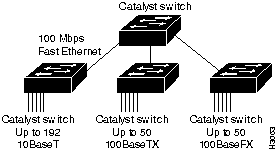
The Catalyst 5000 series switch provides high-density switched Ethernet and Fast Ethernet for both wiring closet and data center applications. The switch includes a single, integrated 1.2-Gbps switching backplane that supports switched Ethernet with repeater connections, and Fast Ethernet with backbone connections, Copper Distributed Data Interface (CDDI), Fiber Distributed Data Interface (FDDI), and Asynchronous Transfer Mode (ATM). The Catalyst 5000 provides switched connections to individual workstations, servers, LAN segments, backbones, or other Catalyst 5000 switches using shielded twisted-pair (STP), unshielded twisted-pair (UTP), and fiber-optic cable. Figure 1 is an example of a configuration using the Catalyst 5000 series switch.
Figure 1 : Cascaded Switches Using Fast Ethernet Interfaces
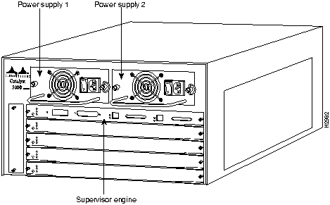
The Catalyst 5000 series switch chassis has five slots. Slot 1 is reserved for the supervisor engine, which provides Layer 2 switching, local and remote management, and dual Fast Ethernet interfaces. The remaining four slots are used for any combination of modules for additional Ethernet, Fast Ethernet, CDDI/FDDI, and ATM connections. Figure 2 shows the rear view of the Catalyst 5000 series switch, which provides access to the supervisor engine, all switching modules, power supplies, and fan assembly.
Figure 2 : Catalyst 5000 Series Switch Chassis Rear View
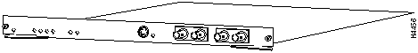
The CDDI module, shown in Figure 3, provides a single- or dual-attachment station connection to two Category 5 UTP Fast Ehernet CDDI interfaces using two RJ-45 female connections.
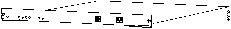
The LEDs provide status information for the module and individual Ethernet port connections. The LEDs are described in the section "CDDI Switching Module LEDs."
FDDI Module MMF (Multimode Fiber) Description
The FDDI module MMF (multimode fiber), shown in Figure 4, provides a single- or dual-attachment station connection to the Fast Ethernet FDDI backbone network using a multimode (MIC) fiber optic connection.
Figure 4 : FDDI Module MMF (Multimode Fiber)
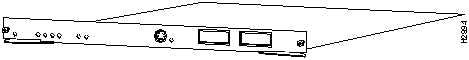
The LEDs provide status information for the module and individual FDDI port connections. The LEDs are described in the section "FDDI Switching Module (Multimode Fiber) LEDs."
FDDI Module SMF (Single-Mode Fiber) Description
The FDDI module SMF (single-mode fiber), shown in Figure 5, provides a single- or dual-attachment station connection to the Fast Ethernet FDDI backbone network using a single-mode ST fiber-optic connection.
Figure 5 : FDDI Module (Single Mode Fiber)
The LEDs provide status information for the module and individual FDDI port connections. The LEDs are described in the section "FDDI Switching Module (Single-mode Fiber) LEDs."
Table 1 lists the FDDI and CDDI module specifications:
Table 1 : FDDI and CDDI Module Specifications
| Description | Specification |
|---|---|
| Dimensions (H x W x D) | 1.2 x 14.4 x 16 in (3 x 35.6 x 40.6 cm) |
| Weight:
FDDI module SMF (single-mode) FDDI module MMF (multimode) CDDI UTP |
4.2 lb (1.9 kg) 4.2 lb (1.9 kg 3 lb (1.36 kg) |
| Environmental Conditions:
Operating temperature Nonoperating temperature Humidity |
32 to 104°F (0 to 40°C) -40 to 167°F (-40 to 75°C) 10 to 90%, noncondensing |
| Connectors | CDDI (RJ-45)
FDDI (MIC and ST) |
| RAM buffer memory | 192 KB per interface |
| Maximum station-to-station cabling distance | FDDI: 50/125-micron multimode fiber: 1.24 miles (2 km)
FDDI: 8/125-micron single-mode fiber: 18.6 miles (30 km) CDDI: Category 5 UTP: 328' (100 m) |
| FDDI transmit power levels:
Single-mode fiber Multimode fiber |
Average optical power: Maximum: --4.0 dBm1 Minimum: --7.0 dBm Maximum: --14.0 dBm Minimum: --18.5 dBm |
| FDDI receive power levels:
Single-mode fiber Multimode fiber |
Average optical sensitivity: --33 dBm Average maximum input power: --14 dBm Average optical sensitivity: --34 dBm Average maximum input power: --14 dBm |
| Frame processing | IP fragmentation (RFC 791)
Translation (802.1h, 802.1i) |
| Network management | SNMP2 agent, Station Management (SMT) Specification, Revision 7.3 |
| Agency approvals:
Safety EMI3 |
UL4 1950, CSA5-C22.2 No. 950-93, and EN60950 FCC Class A (47 CFR, Part 15), CE Mark, EN55022 Class B and VCCI Class 2 with shielded cables |
The five available interface slots on the Catalyst 5000 series switch support a supervisor engine (slot 1 only), and any combination of network interface switching modules (slots 2 through 5), providing the maximum port densities of up to four switched FDDI or CDDI modules.
Each CDDI and FDDI module contains a status LED. When on, this LED indicates that the module is operational and that it is powered up. It does not necessarily mean that the interface ports are functional or enabled.
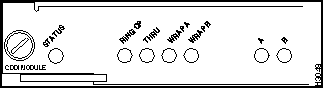
The LEDs on the faceplate of the CDDI module, shown in Figure 6, are described in Table 2.
Table 2 : CDDI Module LED Descriptions
| LED | Description |
|---|---|
| Status | The switch performs a series of self-tests and diagnostic tests.
If all the tests pass, the status LED is green. If a test other than an individual port test fails, the status LED is red. During system boot or if the module is disabled, the LED is orange. During self-test diagnostics, the LED is orange. If the module is disabled, the LED is orange. |
| RingOp | Indicates whether or not the ring is operational.
If the ring is operational, the RingOp LED is green. If the ring is not operational, the RingOp LED is offf. |
| Thru | If the FDDI/CDDI A and B ports are connected to the primary and secondary rings, the Thru LED is green; otherwise, it is off. |
| Wrap A | If the FDDI/CDDI A port is connected to the ring and the B port is isolated, the Wrap A LED is green; otherwise, it is off. |
| Wrap B | If the FDDI/CDDI B port is connected to the ring and the A port is isolated, the Wrap B LED is green; otherwise, it is off. |
| Port A status | If the FDDI/CDDI A port is connected to the ring, the port A LED is green.
If the FDDI/CDDI A port receives a signal but fails to connect, or a dual homing condition exists, the port A LED is orange. The LED is turned off if no receive signal is detected. |
| Port B status | If the FDDI/CDDI B port is connected to the ring, the port B LED is green.
If the FDDI/CDDI B port receives a signal but fails to connect, or a dual homing condition exists, the port B LED is orange. The LED is turned off if no receive signal is detected. |
| In | The optical Bypass switch LED indicates the status of the device connected to the line module. When the LED is on, the Bypass switch is activated and is in Thru mode (the line module is attached to the dual ring). |
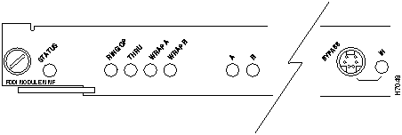
FDDI Module MMF (Multimode Fiber) LEDs
The LEDs on the faceplate of the FDDI module MMF (multimode fiber), shown in Figure 7, are described in Table 3.
Table 3 : FDDI Module (Multimode Fiber) LED Descriptions
| LED | Description |
|---|---|
| Status | The switch performs a series of self-tests and diagnostic tests.
If all the tests pass, the status LED is green. If a test other than an individual port test fails, the status LED is red. During system boot or if the module is disabled, the LED is orange. During self-test diagnostics, the LED is orange. If the module is disabled, the LED is orange. |
| RingOp | Indicates whether or not the ring is operational.
If the ring is operational, the RingOp LED is green. If the ring is not operational, the RingOp LED is off. |
| Thru | If the FDDI/CDDI A and B ports are connected to the primary and secondary rings, the Thru LED is green; otherwise, it is off. |
| Wrap A | If the FDDI/CDDI A port is connected to the ring and the B port is isolated, the wrap A LED is green; otherwise, it is off. |
| Wrap B | If the FDDI/CDDI B port is connected to the ring and the A port is isolated, the wrap B LED is green; otherwise, it is off. |
| Port A status | If the FDDI/CDDI A port is connected to the ring, the port A LED is green.
If the FDDI/CDDI A port receives a signal but fails to connect, or a dual homing condition exists, the port A LED is orange. The LED is turned off if no receive signal is detected. |
| Port B status | If the FDDI/CDDI B port is connected to the ring, the port B LED is green.
If the FDDI/CDDI B port receives a signal but fails to connect, or a dual homing condition exists, the port B LED is orange. The LED is turned off if no receive signal is detected. |
| In | The optical Bypass switch LED indicates the status of the device connected to the line module. When the LED is on, the Bypass switch is activated and is in Thru mode (the line module is attached to the dual ring). |
Figure 7 : FDDI Module MMF (Multimode Fiber) LEDs
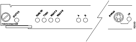
FDDI Module SMF (Single-Mode Fiber) LEDs
The LEDs on the faceplate of the FDDI module SMF (single-mode fiber), shown in Figure 8, are described in Table 4.
Table 4 : FDDI Module SMF (Single-Mode Fiber) LED Descriptions
| LED | Description |
|---|---|
| Status | The switch performs a series of self-tests and diagnostic tests.
If all the tests pass, the status LED is green. If a test other than an individual port test fails, the status LED is red. During system boot or if the module is disabled, the LED is orange. During self-test diagnostics, the LED is orange. If the module is disabled, the LED is orange.. |
| RingOp | Indicates whether or not the ring is operational.
If the ring is operational, the RingOp LED is green. If the ring is not operational, the RingOp LED is off. |
| Thru | If the FDDI/CDDI A and B ports are connected to the primary and secondary rings, the Thru LED is green; otherwise, it is off. |
| Wrap A | If the FDDI/CDDI A port is connected to the ring and the B port is isolated, the Wrap A LED is green; otherwise, it is off.. |
| Wrap B | If the FDDI/CDDI B port is connected to the ring and the A port is isolated, the Wrap B LED is green; otherwise, it is off. |
| Port A status | If the FDDI/CDDI A port is connected to the ring, the port A LED is green.
If the FDDI/CDDI A port receives a signal but fails to connect, or a dual homing condition exists, the port A LED is orange. The LED is turned off if no receive signal is detected. |
| Port B status | If the FDDI/CDDI B port is connected to the ring, the port B LED is green.
If the FDDI/CDDI B port receives a signal but fails to connect, or a dual homing condition exists, the port B LED is orange. The LED is turned off if no receive signal is detected. |
| In | The optical Bypass switch LED indicates the status of the device connected to the line module. When the LED is on, the Bypass switch is activated and is in Thru mode (the line module is attached to the dual ring). |
Figure 8 : FDDI Module SMF (Single-Mode Fiber) LEDs
When preparing your site for network connections to the switch, you need to consider a number of factors related to each type of interface:
Before installing the switch, have all additional external equipment and cables on hand. If you intend to build your own cables, refer to the cable pinouts in the appendix "Cabling Specifications" in the Catalyst 5000 Series Installation. For ordering information, contact a customer service representative.
Fast Ethernet Distance Limitations
The distance and rate limits discussed in this section are the IEEE recommended maximum speeds and distances for signaling; however, if you understand the electrical problems that may arise and can compensate for them, you should get good results with rates and distances greater than those described here. But, you do so at your own risk. The following distance limits are provided as guidelines for planning your network connections before installation.
CDDI Transceivers and Cable Connectors
The CDDI transceiver supports distances of up to 330 feet (100.6 meters). The CDDI connector is a CDDI-standard physical sublayer (PHY) connector that encodes and decodes the data into a format acceptable for UTP transmission. The CDDI connector accepts standard UTP cable using an RJ-45 connector, as shown in Figure 9.
Figure 9 : CDDI Interface RJ-45 Connector

Confirm that all existing cables conform with CDDI distance requirements and ensure that you have the proper connectors (modular RJ-45). Following are cable and distance specifications:
When you plan your CDDI installation, remember the following:
The FDDI standard sets the maximum distances between stations to the fiber lengths listed in Table 5. The maximum circumference of the FDDI network is only half the specified distance because of signal wrapping or loopback during fault correction. The standard allows a maximum of 500 stations. Both single-mode and multimode transceiver types provide 11 dB of optical power.
Table 5 : FDDI Maximum Transmission Distances
| Transceiver Type | Maximum Distance Between Stations |
|---|---|
| Single-mode | 18.6 miles (30 km) |
| Multimode | 1.2 miles (2 km) |
| UTP | 328 feet (100 meters) |
Table 6 : Typical Fiber-Optic Link Attenuation and Dispersion Limits
| Single-Mode | Multimode | |
|---|---|---|
| Attenuation | 0.5 dB | 1.0 dB/km |
| Dispersion limit | No limit | 500 MHz/km1 |
Fiber-optic transceivers on the FDDI modules provide a direct interface between the switch and the FDDI ring. The FDDI modules support multimode transceivers. Multimode transceivers provide a Class A dual attachment interface that can be connected to a Class A or a Class B station. Class A is a dual attachment station (DAS) with primary and secondary rings; Class B is a single attachment station (SAS) with only a primary ring.
FDDI networks use two types of fiber-optic cable---single-mode and multimode. Mode refers to the angle at which light rays (signals) are reflected and propagated through the optical-fiber core, which acts as a waveguide for the light signals. Multimode fiber has a relatively thick core (62.5/125-micron) that reflects light rays at many angles. Although multimode fiber allows more light signals to enter at a greater variety of angles (modes), the different angles create multiple propagation paths that cause the signals to spread out in time and limit the rate at which data can be accurately received. Multimode transmitters usually use LEDs as a light source, and single-mode transmitters use a laser diode, which is capable of sustaining faster data rates. Multimode transmitters use a photodiode detector at the receiver to translate the light signal into electrical signals.
FDDI Transceivers and Cable Connectors
The multimode transceiver supports distances up to 1.2 miles (2 kilometers). The multimode connector is an FDDI-standard physical sublayer (PHY) connector that encodes and decodes the data into a format acceptable for fiber transmission. The multimode connector accepts standard 62.5/125-micron multimode fiber-optic cable using the MIC and, with proper cable terminators, can accept 50/125-micron fiber-optic cable. Multimode and single-mode uses the integrated MIC connector, as shown in Figure 10, at the FDDI modules and the network ends.
Figure 10 : Multimode FDDI Network Interface Connector (MIC Type)

The single-mode transceivers support distances up to 18.6 miles (30 kilometers). The single-mode connector accepts standard 8.7 or 10/125-micron single-mode fiber-optic cable using the ST type connectors for transmit and receive ports. (See Figure 11.)
Figure 11 : FDDI Network Interface Connector (ST Type)
![]()
The FDDI modules provide a control port for an optical bypass switch. The control port allows the light signal to pass directly through the bypass switch and completely bypass the FDDI module transceivers when the interface has failed or is shut down. Most optical bypass switches provide the necessary interface cables for connection to the MIC connectors on the FDDI module. However, not all manufacturers use the same type of DIN connector for the control port; some manufacturers use a DIN, and some use a smaller version, a mini-DIN. Figure 7 and Figure 8 show the optical bypass connector on the FDDI module faceplate.
The following guidelines will help to ensure your safety and protect the equipment. This list is not inclusive of all potentially hazardous situations that you may be exposed to when installing the switch, so be alert.
The supervisor engine, modules, and redundant power supplies are designed to be removed and replaced while the system is operating without presenting an electrical hazard or damage to the system. Before removing a redundant power supply, ensure that the first supply is powered on. However, you must shut down the system before removing or replacing any of the replaceable components inside the front panel, for example, the backplane. Never install equipment that appears damaged.
Follow these basic guidelines when working with any electrical equipment:
In addition, use the guidelines that follow when working with any equipment that is disconnected from a power source but still connected to telephone wiring or other network cabling.
Preventing Electrostatic Discharge Damage
Electrostatic Discharge (ESD) damage occurs when electronic or components are improperly handled, resulting in complete or intermittent failures. The supervisor engine and switching modules each consist of a printed circuit board (PCB) fixed in a metal carrier. Electromagnetic interference (EMI) shielding, connectors, and a handle are integral components of the carrier. Although the metal carrier helps to protect modules from ESD, use a preventive antistatic strap whenever you handle the supervisor engine or switching modules. Handle the carriers by the handles and the carrier edges only, never touch the modules or connector pins.
Following are guidelines for preventing ESD damage:
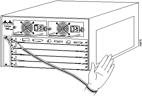
Figure 12 : Placement of ESD Wrist Strap
Installing and Configuring Modules
All switching modules support hot swapping, letting you install, remove, replace, and rearrange them without turning off the system power. When the system detects that a switching module has been installed or removed, it automatically runs diagnostic and discovery routines, acknowledges the presence or absence of the module, and resumes system operation without any operator intervention.
The hot-swap feature lets you remove and replace switching modules while the system is operating. You do not need to notify the software or shut down the system power. All switching modules support hot swapping.
The switching module contains a bus-type connector that connects to the backplane. Each connector consists of a set of tiered pins in two lengths. The pins send specific signals to the system as they make contact with the backplane. The system assesses the signals it receives and the order in which it receives them to determine what event is occurring and what task it needs to perform, such as reinitializing new interfaces or shutting down removed ones.
For example, when inserting the switching module, the longest pins make contact with the backplane first, and the shortest pins make contact last. The system recognizes the signals and the sequence in which it receives them. The system expects to receive signals from individual pins in this logical sequence.
When you remove or insert a switching module, the backplane pins send signals to notify the system, and performs as follows:
When you insert a new switching module, the system runs a diagnostic test on the new interfaces and compares them to the existing configuration. If this initial diagnostic fails, the system remains off line for another 15 seconds while it performs a second set of diagnostic tests to determine whether or not the switching module is faulty and if normal system operation is possible.
If the second diagnostic test passes, indicating that the system is operating normally and a new switching module is faulty, the system resumes normal operation but leaves the new interfaces disabled.
If the second diagnostic test fails, the system crashes, which usually indicates that the new supervisor engine or a switching module created a problem in the bus and should be removed
Avoiding Problems When Inserting and Removing Switching Modules
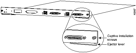
The function of the ejector levers (see Figure 13) on the switching module is to align and seat the board connectors in the backplane. Failure to use the ejector levers and insert the switching module properly can disrupt the order in which the pins make contact with the backplane. Follow the installation and removal instructions carefully, and review the following examples of incorrect insertion practices and results:
It is also important to use the ejector levers when removing a switching module, ensuring that its connector pins disconnect from the backplane in the logical sequence expected by the system. A switching module partially connected to the backplane can hang the bus. Detailed steps for correctly performing a hot swap are included in the following procedures for installing and removing a switching module.
Figure 13 : Ejector Levers and Captive Installation Screws (Supervisor Engine Module Shown)
You need a flat-blade screwdriver to remove any filler (blank) modules and to tighten the captive installation screws that secure the modules in their slots. Whenever you handle modules, you should use a wrist strap or other grounding device to prevent ESD damage. See the section "Preventing Electrostatic Discharge Damage."
Take the following steps to remove a switching module:
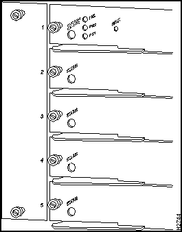
You can install switching modules in any of the four switching module slots, numbered 2 through 5 from top to bottom, when viewing the chassis from the rear. (See Figure 14.) The top slot contains the supervisor engine---a required system component. Switching module fillers, blank switching module carriers, are installed in slots without switching modules to maintain consistent airflow through the switching module compartment.
Following is the procedure for installing a module:
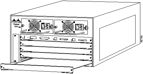
Figure 15 : Module Installation
Hot-Swapping Procedure Sample Screen Display
When you remove and replace switching modules, the system provides status messages on the console screen. The messages are for information only. In the following sample display, using the show system and show module commands, you can follow the events logged by the system when a switching module is removed from slot 2. When the show port command is used to query the module, the system reports notconnect.When the module is reinserted, the system marks the module as ok.
After you install the switching module, use the following information to configure the module and the individual interfaces on the Ethernet switching port module. The section "Port Addresses" contains an overview of the port and module numbering scheme used to configure the Catalyst 5000 series switching modules. The section "CDDI/FDDI Configuration" describes how to configure the ports on the Ethernet switching module. And the section "CDDI/FDDI Configuration" describes the procedures you should use to confirm that the Ethernet switching module is configured correctly.
Each interface in the Catalyst 5000 series switch is designated by several different types of addresses. The physical interface address is the actual physical location (slot and port) of the interface connector within the chassis. The system software uses the physical addresses to control activity within the switch and to display status information. These physical slot and port addresses are not used by other devices in the network. They are specific to the individual switch and its internal components and software.
A second type of address is the MAC or hardware address---a standard data link layer address required for every port or device connected to a network. Other devices in the network use these addresses to locate specific ports in the network, and to create and update routing tables and data structures. The Catalyst 5000 series switch uses a unique method to assign and control the MAC addresses of its interfaces.
The following sections describe how the Catalyst 5000 series switch assigns and controls both the physical and MAC addresses for interfaces within the chassis.
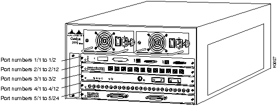
In the Catalyst 5000 series switch, physical port addresses specify the actual physical location of each port on the rear of the switch. (See Figure 16.) The address is composed of a two-part number in the format slot number/port number. The first number identifies the slot in which the switching module is installed. Module slots are numbered 1 to 5, from top to bottom. The second number identifies the physical port number on the switching module. The port numbers always begin at 1 and are numbered from the left port to right port when facing the rear of the switch. The number of additional ports (n/1, n/2, and so on) depends on the number of ports available on the module.
Interface ports maintain the same address regardless of whether other switching modules are installed or removed. However, when you move a switching module to a different slot, the first number in the address changes to reflect the new slot number. For example, on a 12-port 10/100BaseTX switching module in slot 2, the address of the left port is 2/1 and the address of the right port is 2/12. If you remove the 12-port 10/100Base TX switching module from slot 2 and install it in slot 4, the addresses of those same ports become 4/1 and 4/12.
Figure 16 : Interface Port Address Examples
The Fast Ethernet switching module supports up to 12 interfaces---n/1 through n/12. Switching modules are always n/1 to n/12 because each switching module supports at least twelve interfaces. (Switching modules with more than 12 interfaces are addressed n/1 through n/n.)
You can identify module interfaces by physically checking the slot/port location on the back of the switch. Software commands are used to display information about a specific interface in the switch. To display information about every interface, use the show port command without parameters. To display information about a specific interface, use the show port command with the interface type and port address in the format show port [mod_num/port_num]. If you abbreviate the command (sho po), and do not include parameters, the system interprets the command as show port and displays the status of all interfaces.
Following is an example of how the show port command without parameters displays status information (including the physical slot and port address) for each interface in the switch.
For complete descriptions of the commands used to configure and maintain the Catalyst 5000 series switch, refer to the Catalyst 5000 Series Configuration Guide and Command Reference.
All network interface connections require a unique MAC address. The switch uses a MAC address allocator, stored in the supervisor engine's nonvolatile memory which identifies all system interface addresses. Each switch interface, configured or not, is allocated a MAC address. For instance, interface 2/10 is allocated a MAC address as a Fast Ethernet connection configured in slot 2, port 10; interface 2/11 is not configured but is also allocated an address. This addressing scheme is important, especially when hot-swapping modules, because it gives the switch the intelligence to identify the state---connected or notconnect---of each interface on the switch.
This section describes how to use the administrative interface to configure the CDDI/FDDI ports of the Catalyst 5000 series switch.
To configure Fast Ethernet ports, complete the tasks in the following sections:
The features you can customize have default values that will most likely suit your environment and probably need not be changed. The default values of these features are set as follows:
If needed, you can customize the preceding features to fit your configuration by performing any of the following tasks. Each task is covered in a subsection that follows.
Customize the Default IPX Protocol Translations
As a normal function, the Catalyst 5000 series switch can forward IPX packets received on FDDI ports to Ethernet ports, or it can forward IPX packets received on Ethernet ports to FDDI ports. To do this, the switch must be configured for specific IPX protocol translations. By default, the following IPX protocol translations are configured:
You can customize these settings if your environment requires it.
Setting the FDDI SNAP to Ethernet Translation
The FDDI SNAP frame can be translated into the following Ethernet frames:
To specify the FDDI protocol to which Ethernet 8023RAW packets are translated, perform the following steps in privileged mode:
See sections "Checking the Configuration" and "Example of Displaying Bridge Information" in the Catalyst 5000 Series Installation Guide.
Setting the FDDI 802.2 to Ethernet Translation
The FDDI SNAP frame can be translated into the following Ethernet frames:
To specify the FDDI protocol to which Ethernet 8023RAW packets are translated, perform the following steps in privileged mode:
See sections "Checking the Configuration" and "Example of Displaying Bridge Information" in the Catalyst 5000 Series Installation Guide.
Figure 17 : set bridge ipx snaptoether 8023 Command Example
Figure 18 : show bridge Command Example
Setting the Ethernet 802.3 RAW to FDDI Protocol
The FDDI 802.2 frame can be translated into the following Ethernet frames:
To specify the Ethernet frame to which IPX FDDI SNAP packets are translated, perform the following steps in privileged mode:
The following example sets the IPX translation protocol for FDDI 802.2 to 802.3:
Figure 19 : set bridge ipx 8022 toether 8023 Command Example
The following example sets the IPX translation protocol for FDDI SNAP to Ethernet SNAP:
Figure 20 : set bridge ipx snaptoether snap Command Example
Figure 21 : show bridge Command Example
Set Minimum Time to Transfer the FDDI PHY Line State
The TL_MIN parameter sets the minimum time to transmit an FDDI physical sublayer (PHY) line state before advancing to the next physical connection management (PCM) state. This setting affects the station and switch interoperability and might hinder the implementation of FDDI repeaters. By default, the TL_MIN parameter is set to 40 microseconds. Normally, you will not need to adjust this parameter. However, you can customize the TL_MIN setting if needed. To do this, perform the following steps in privileged mode:
Figure 22 : set fddi tlmin Command Example
Figure 23 : show fddi Command Example
Set Interval Between Neighbor Notification Frames
The TNotify parameter sets the interval (in seconds) between neighbor notification frames. These frames are sent out to notify neighboring devices of FDDI module MAC addresses. Usually, the default setting of 30 seconds is sufficient. By shortening the interval, you cause more notification frames to be sent. However, if you need to adjust this setting, perform the following steps in privileged mode:
Figure 24 : set fddi tnotify Command Example
Figure 25 : show fddi Command Example
The TRequest parameter specifies the FDDI switch's desired value for the Token Ring Timer (TRT) for negotiating the TRT with other stations. The TRT is used to control ring scheduling during normal operation and to detect and recover from serious ring error situations. Whenever the TRT value expires, the station uses the TRequest value to negotiate with other stations for the lowest value. The default setting of 16,5000 microseconds is sufficient for most networks. However, if you need to modify this setting, perform the following steps in privileged mode:
Figure 26 : set fddi trequest Command Example
Figure 27 : show fddi Command Example
The user-data string identifies the user data string in the SMT MIB of an FDDI module. The default value is "Catalyst 5000." This value should be modified to a more meaningful description. To modify this parameter, perform the following steps in privileged mode:
Figure 28 : set fddi Command Example
Figure 29 : show fddi Command Example
IP fragmentation allows the Catalyst 5000 series switch to fragment large FDDI IP frames (frames greater than 1514 bytes) into multiple smaller packets so that they can be transmitted on an Ethernet segment. By default, IP fragmentation is enabled. If you want the large packets to be dropped instead of fragmented, disable fragmentation:
To reenable IP fragmentation, perform the following steps in privileged mode:
Figure 30 : set ip fragmentation disable Command Example
Figure 31 : show ip route Command Example
Disable ICMP Unreachable Messages
When enabled, the switch returns an ICMP unreachable message to the Internet source host whenever it receives an IP datagram that it cannot deliver. When disabled, the switch does not notify the Internet source host when it receives an IP datagram that it cannot deliver. You can disable unreachable messages enabled if desired. To do this, perform the following steps in privileged mode:
To reenable IP unreachable messages, perform the following steps in privileged mode:
Figure 32 : set ip unreachable disable Command Example
Figure 33 : show ip route Command Example
The LER-Alarm value defines the link error rate (LER) at which a link connection exceeds a preset alarm threshold. This value is used in the link error rate threshold test. The default setting of 8 (10¯8) link errors per second is sufficient for most networks. However, if you need to modify this setting, perform the following steps in privileged mode:
Figure 34 : set fddi alarm Command Example
Figure 35 : show fddi Command Example
Set the Link Error Rate Cutoff
The LER-Cutoff value determines the link error rate (LER) at which a connection will be flagged as faulty. This value is used in the link error rate threshold test. The default setting of 7 (10¯7) is sufficient for most networks. However, if you need to modify this setting, perform the following steps in privileged mode:
Figure 36 : set fddi cutoff Command Example
Figure 37 : show fddi Command Example
Assign a name to each port. To set a port name, perform the following tasks in administrative mode:
Figure 38 : set port name Command Example
Figure 39 : Sample show port Command Display
VLANs allow ports on the same or different switches to be grouped so that traffic is confined to members of that group only. This feature restricts unicast, broadcast, and multicast traffic (flooding) to ports included in the same VLAN.
The set vlan command groups ports. The default configuration for all switched Ethernet ports and Ethernet repeater ports in VLAN 1. You can enter groups of ports as individual entries, such as 2/1,3/3,3/4,3/5. You can also use a hyphenated format to indicate a range of ports, such as 2/1, 3/3-5.
To create a VLAN across a networking domain, perform the following steps in privileged mode:
Figure 40 : set vtp Command Example
Figure 41 : show vtp domain Command Example
Figure 42 : set vlan Command Example
Figure 43 : VLAN Configuration Across a Management Domain
Figure 44 : show vlan Command Display Sample
To create a VLAN, perform the following tasks in privileged mode:
Figure 45 : set vlan Command Example
Figure 46 : VLAN Configuration
Figure 47 : Sample show vlan Command Display
Use the set trunk command to configure trunks on ports, and to configure the mode for the trunk: on, off, desirable, or auto. To establish a trunk, the port on each Catalyst 5000 series switch must be configured as a trunk port. To establish trunks, perform the following steps in privileged mode:
Figure 48 : set trunk Command Example
Figure 49 : show trunk Command Display Sample
Setting Up an FDDI 802.10 Configuration
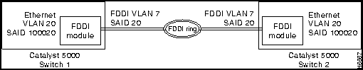
The FDDI module is basically an FDDI-Ethernet translation bridge. It translates packets on the external FDDI ring into Ethernet packets within the Catalyst 5000. That is, inside the Catalyst 5000 Ethernet VLAN packets are translated into FDDI VLAN packets and encoded in 802.10 format with a SAID value before they are transmitted across an external FDDI trunk to another Catalyst 5000. The Catalyst 5000 that receives the packets from the trunk decodes the 802.10 format using the SAID value and internally translates the FDDI VLAN packets into Ethernet VLAN packets. Each Ethernet VLAN requires a unique FDDI VLAN translation.
For example, to connect Ethernet VLAN 20 in switch 1 to Ethernet VLAN 20 in switch 2, as shown in Figure 50, you would use a VTP server to set up the configuration as follows:
Figure 50 : FDDI 802.10 Configuration Example
The Catalyst 1200 series switch is hardcoded with a specific VLAN-to-SAID configuration. Therefore, if you are connecting a Catalyst 5000 Ethernet VLAN to a Catalyst 1200 Ethernet VLAN, the SAID value of the FDDI VLAN must be the same value as the Ethernet VLAN. For example, if a Catalyst 1200 Ethernet VLAN value is 20, the translation FDDI VLAN SAID value must be 20.
Before setting up an FDDI 802.10 VLAN configuration, refer to the section"Set Virtual LANs" to set up a VTP domain. After completing these tasks, perform the following steps in privileged mode to set up the FDDI 802.10 VLAN configuration:
The following examples add a new Ethernet and FDDI VLAN to the existing configuration.
Figure 51 : set vlan Command Example to Create a VLAN
Figure 52 : set vlan Command Example to Assign a VLAN to an Ethernet Port
Figure 53 : set vlan Command Example to Create an FDDI VLAN
Figure 54 : set vlan Command Example to Translate an Ethernet VLAN to an FDDI VLAN
Figure 55 : set trunk Command Example
Figure 56 : show vlan Command Example
This section describes procedures to use to confirm that your Ethernet (10BaseT 24 port) module is installed and configured correctly.
Use the ping command to send Internet Control Message Protocol (ICMP) echo request packets to another node on the network. Enter Ctrl-C to stop pinging.
Syntax Description
Following are sample results of the ping command:
Example
In the following example, host with IP alias elvis is pinged a single time, then pinged once every second until you enter Ctrl C to stop pinging:
Use the show system command to display the power supply, fan, temperature alarm, system, and modem status; the number of days, hours, minutes, and seconds since the last system restart; the baud rate; the MAC address range; and the system name, location, and contact.
Example
In the following example, the system status and other information is displayed:
Displaying the System Configuration
Use the show config command to display the current system configuration:
Displaying the Port Configuration
Use the show port command to display the current system configuration:
Copyright 1988-1996 © Cisco Systems Inc.
![]()
![]()
![]()
![]()
![]()
![]()
![]()
![]()
Console> (enable) show system
PS1-Status PS2-Status Fan-Status Temp-Alarm Sys-Status Uptime d,h:m:s Logout
---------- ---------- ---------- ---------- ---------- -------------- ---------
ok         none       ok         off        ok         0,00:21:41     none

PS1-Type   PS2-Type   Modem   Baud  Traffic Peak Peak-Time
---------- ---------- ------- ----- ------- ---- -------------------------
WS-C5101   none       disable  9600   0%      0% Tue May 14 1996, 14:37:31

System Name              System Location          System Contact
------------------------ ------------------------ ------------------------
Console> (enable)

Console> (enable) show module
Mod Module-Name          Ports Module-Type           Model   Serial-Num Status
--- -------------------- ----- --------------------- -------- --------- -------
1                        2     100BaseTX Supervisor  WS-X5009 002650014 ok
2                        10    FDDI 100BaseFX        WS-X5011 002475046 ok
4                        48    4 Segment 10BaseT Eth WS-X5020 001336146 ok

Mod MAC-Address(es)                           Hw     Fw     Sw
--- ----------------------------------------  ------ ------ ----------------
1   00-40-0b-ac-80-00 thru 00-40-0b-ac-83-ff  1.81   1.5    2.1
2   00-40-0b-4c-92-58 thru 00-40-0b-4c-92-6f  1.0    1.4    2.1
4   00-40-0b-ff-00-00 thru 00-40-0b-ff-00-03  0.2    2.1(1) 2.1
Console> (enable)

Console> (enable) show port 2/10
Port Name                 Status     Vlan       Level  Duplex Speed Type
---- -------------------- ---------- ---------- ------ ------ ----- -----------
2/10                      connected  1          normal   half    10 10BaseT

Port Align-Err  FCS-Err    Xmit-Err   Rcv-Err
---- ---------- ---------- ---------- ----------
2/10          0          0          0          0

Port Single-Col Multi-Coll Late-Coll  Excess-Col Carri-Sens Runts     Giants
---- ---------- ---------- ---------- ---------- ---------- --------- ---------
2/10          0          0          0          0          0         0         0

Last-Time-Cleared
--------------------------
Tue May 14 1996, 14:37:31
Console> (enable)
Console> (enable) show port

Port Name                  Status     Vlan       Level  Duplex Speed Type
---- --------------------  ---------- ---------- ------ ------ ----- -----------
1/1  100BaseTX Supervisor  connected  trunk      normal   half   100  100BaseTX
1/2  100BaseTX Supervisor  connected  1          normal   half   100  100BaseTX
2/1  FDDI 100BasFX         connected  1          normal   half   100  100BaseFX
2/2  10BaseFL 12 Port      connected  1          normal   half   10   10BaseFL
2/3  10BaseFL 12 Port      connected  1          normal   half   10   10BaseFL
2/4  10BaseFL 12 Port      connected  1          normal   half   10   10BaseFL
2/5  10BaseFL 12 Port      connected  1          normal   half   10   10BaseFL
.
.
.
4/45                       notconnect 1          normal   half    10  10BaseT
4/46                       notconnect 1          normal   half    10  10BaseT
4/47                       notconnect 1          normal   half    10  10BaseT

Port Align-Err  FCS-Err    Xmit-Err   Rcv-Err
---- ---------- ---------- ---------- ----------
1/1           0          0          0          0
1/2           0          0          0          0
2/1           0          0          0          0
2/2           0          0          0          0
2/3           0          0          0          0
.
.
.
2/18          0          0          0          0
2/19          0          0          0          0

2/20          0          0          0          0
2/21          0          0          0          0
2/22          0          0          0          0
2/23          0          0          0          0
2/24          0          0          0          0TT


Port Auto-Parts Giants     Data-Rate  FCS-Err    Runts      Rcv-frms   Src-Addr
                           Mismatch                                    Changes
---- ---------- ---------- ---------- ---------- ---------- ---------- --------
4/1           0          0          0          0          0          0        0
4/2           0          0          0          0          0          0        0
4/3           0          0          0          0          0          0        0
4/4           0          0          0          0          0          0        0
4/5           0          0          0          0          0          0        0
4/6           0          0          0          0          0          0        0
.
.
.
4/43          0          0          0          0          0          0        0
4/44          0          0          0          0          0          0        0
4/45          0          0          0          0          0          0        0
4/46          0          0          0          0          0          0        0
4/47          0          0          0          0          0          0        0
4/48          0          0          0          0          0          0        0

Port Rcv-Multi  Rcv-Broad  Good-Bytes Align-Err  Short-Evnt Late-Coll Collision
---- ---------- ---------- ---------- ---------- ---------- --------- ---------
4/1           0          0          0          0          0         0         0
4/2           0          0          0          0          0         0         0
4/3           0          0          0          0          0         0         0
4/4           0          0          0          0          0         0         0
.
.
.
4/42          0          0          0          0          0         0         0
4/43          0          0          0          0          0         0         0
4/44          0          0          0          0          0         0         0
4/45          0          0          0          0          0         0         0
4/46          0          0          0          0          0         0         0
4/47          0          0          0          0          0         0         0
4/48          0          0          0          0          0         0         0

Last-Time-Cleared
--------------------------
Tue May 14 1996, 14:37:31
Console> (enable)
Task
Command
set bridge ipx snaptoether {8023 | SNAP | EII | 8023RAW }
show bridge
Task
Command
set bridge ipx snaptoether {8023 | SNAP | EII | 8023RAW }
show bridge
Console> (enable) set bridge ipx snaptoether 8023
Bridge snaptoether default IPX translation set.
Console> (enable)
Console> (enable) show bridge
APaRT Enabled
FDDICHECK Enabled
IP fragmentation Enabled
Default IPX translations:
    FDDI SNAP  to Ethernet     8023raw
    FDDI 802.2 to Ethernet     8023raw
    Ethernet 802.3 Raw to FDDI snap
Console> (enable)
Task
Command
set bridge ipx 8022toether {8023 | SNAP | EII | 8023RAW }
show bridge
Console> (enable) set bridge ipx 8022toether 8023
Module 4 8022toether translation set.
Console> (enable)
Console> (enable) set bridge ipx snaptoether snap
Module 4 snaptoether translation set
Console> (enable)
Console> (enable) show bridge
APaRT Enabled
FDDICHECK Enabled
IP fragmentation Enabled
Default IPX translations:
    FDDI SNAP  to Ethernet     8023raw
    FDDI 802.2 to Ethernet     8023raw
    Ethernet 802.3 Raw to FDDI snap
Console> (enable)
Task
Command
set fddi tlmin mod_num/port_num usecs
show fddi
Console> (enable) set fddi tlmin 4/1 40
Port 4/1 tlmin set to 40.
Console> (enable)
Console> (enable) show fddi
Mod  SMT User-Data               T-Notify  TReq
---  --------------------------  --------  -------
4    Engineering                 15        3500
5    abc                         20        150000

Port   Tlmin     Ler-CutOff  Ler-Alarm
-----  --------  ----------  ---------
4/1    40        10          11
4/2    40        10          11
5/1    40        10          11
5/2    40        9           12
Console>(enable)
Task
Command
set fddi tnotify mod_num time
show fddi
Console> (enable) set fddi tnotify 4/1 15
Module 4 tnotify set to 15.
Console> (enable)
Console> (enable) show fddi
Mod  SMT User-Data               T-Notify  TReq
---  --------------------------  --------  -------
4    Engineering                 15        3500
5    abc                         20        150000

Port   Tlmin     Ler-CutOff  Ler-Alarm
-----  --------  ----------  ---------
4/1    40        10          11
4/2    40        10          11
5/1    40        10          11
5/2    40        9           12
Console> (enable)
Task
Command
set fddi treq mod_num time
show fddi
Console> (enable) set fddi trequest 4 3500
Mac 4/1 treq set to 3500.
Console> (enable)
Console> (enable) show fddi
Mod  SMT User-Data               T-Notify  TReq
---  --------------------------  --------  -------
4    Engineering                 15        3500
5    abc                         20        150000

Port   Tlmin     Ler-CutOff  Ler-Alarm
-----  --------  ----------  ---------
4/1    40        10          11
4/2    40        10          11
5/1    40        10          11
5/2    40        9           12
Console> (enable)
Task
Command
set fddi userdata mod_num userdata_string
show fddi
Console> (enable) set fddi userdata 4 Engineering
Module 4 userdata set to Engineering.
Console> (enable)
Console> (enable) show fddi
Mod  SMT User-Data               T-Notify  TReq
---  --------------------------  --------  -------
4    Engineering                 15        3500
5    abc                         20        150000

Port   Tlmin     Ler-CutOff  Ler-Alarm
-----  --------  ----------  ---------
4/1    40        10          11
4/2    40        10          11
5/1    40        10          11
5/2    40        9           12
Console> (enable)
Task
Command
set ip fragmentation disable
show ip route
Task
Command
set ip fragmentation enable
show ip route
Console> (enable) set ip fragmentation disable
IP fragmentation disabled for module 4
Console> (enable)
Console> (enable) show ip route
Fragmentation   Redirect   Unreachable
-------------   --------   -----------
enabled         enabled    disabled

Destination     Gateway         Flags   Use         Interface
--------------- --------------- ------  ----------  ---------
default         atlas           UG            6090  sc0
lnf             cat7-lnf        U                0  sc0
default         default         UH               0  sl0
Console> (enable)
Task
Command
set ip unreachable disable
show ip route
Task
Command
ip unreachable enable
show ip route
Console> (enable) set ip unreachable disable
Console> (enable)
Console> (enable) show ip route
Fragmentation   Redirect   Unreachable
-------------   --------   -----------
enabled         enabled    disabled

Destination     Gateway         Flags   Use         Interface
--------------- --------------- ------  ----------  ---------
default         atlas           UG            6090  sc0
lnf             cat7-lnf        U                0  sc0
default         default         UH               0  sl0
Console> (enable)
Task
Command
set fddi alarm mod_num/port_num value
show fddi
Console> (enable) set fddi alarm 4/1 11
Port 4/1 alarm value set to 11.
Console> (enable)
Console> (enable) show fddi
Mod  SMT User-Data               T-Notify  TReq
---  --------------------------  --------  -------
4    Engineering                 15        3500
5    abc                         20        150000

Port   Tlmin     Ler-CutOff  Ler-Alarm
-----  --------  ----------  ---------
4/1    40        10          11
4/2    40        10          11
5/1    40        10          11
5/2    40        9           12
Console> (enable)
Task
Command
set fddi cutoff mod_num/port_num value
show fddi
Console> (enable) set fddi cutoff 4/1 10
Port 4/1 cutoff value set to 10.
Console> (enable)
Console> (enable) show fddi
Mod  SMT User-Data               T-Notify  TReq
---  --------------------------  --------  -------
4    Engineering                 15        3500
5    abc                         20        150000

Port   Tlmin     Ler-CutOff  Ler-Alarm
-----  --------  ----------  ---------
4/1    40        10          11
4/2    40        10          11
5/1    40        10          11
5/2    40        9           12
Console> (enable)
Task
Command
Configure a name for a port. Figure 38 shows an example set port name command.
set port name mod_num/port_num [name_string]
Verify that the port name is correct. Figure 39 shows an example show port command. Port names are listed in the Name column.
show port mod_num/port_num
Console> (enable) set port name 1/1 Management Port
Port 1/1 name set.
Console> (enable) set port name 1/2 InterSwitch Link
Port 1/2 name set.
Console> (enable) show port

Port Name                  Status     Vlan       Level  Duplex Speed Type
---- --------------------  ---------- ---------- ------ ------ ----- -----------
1/1  Management Port       connected  1          normal   half   100  100BaseTX
1/2  InterSwitch Link      connected  trunk      normal   half   100  100BaseTX
2/1  FDDI 100BasFX         connected  1          normal   half   100  100BaseFX
2/2  10BaseFL 12 Port      connected  1          normal   half   auto 10BaseFL
2/3  10BaseFL 12 Port      connected  1          normal   half   auto 10BaseFL
2/4  10BaseFL 12 Port      connected  1          normal   half   auto 10BaseFL
2/5  10BaseFL 12 Port      connected  1          normal   half   auto 10BaseFL
.
.
4/45                       notconnect 1          normal   half    10  10BaseT
4/46                       notconnect 1          normal   half    10  10BaseT
4/47                       notconnect 1          normal   half    10  10BaseT

Port Align-Err  FCS-Err    Xmit-Err   Rcv-Err
---- ---------- ---------- ---------- ----------
1/1           0          0          0          0
1/2           0          0          0          0
2/1           0          0          0          0
2/2           0          0          0          0
2/3           0          0          0          0
.
.
.
2/18          0          0          0          0
2/19          0          0          0          0
2/20          0          0          0          0
2/21          0          0          0          0
2/22          0          0          0          0
2/23          0          0          0          0
2/24          0          0          0          0TT


Port Auto-Parts Giants     Data-Rate  FCS-Err    Runts      Rcv-frms   Src-Addr
                           Mismatch                                    Changes
---- ---------- ---------- ---------- ---------- ---------- ---------- --------
4/1           0          0          0          0          0          0        0
4/2           0          0          0          0          0          0        0
4/3           0          0          0          0          0          0        0
4/4           0          0          0          0          0          0        0
4/5           0          0          0          0          0          0        0
4/6           0          0          0          0          0          0        0
.
.
.
4/43          0          0          0          0          0          0        0
4/44          0          0          0          0          0          0        0
4/45          0          0          0          0          0          0        0
4/46          0          0          0          0          0          0        0
4/47          0          0          0          0          0          0        0
4/48          0          0          0          0          0          0        0


Port Rcv-Multi  Rcv-Broad  Good-Bytes Align-Err  Short-Evnt Late-Coll Collision
---- ---------- ---------- ---------- ---------- ---------- --------- ---------
4/1           0          0          0          0          0         0         0
4/2           0          0          0          0          0         0         0
4/3           0          0          0          0          0         0         0
4/4           0          0          0          0          0         0         0
.
.
.
4/42          0          0          0          0          0         0         0
4/43          0          0          0          0          0         0         0
4/44          0          0          0          0          0         0         0
4/45          0          0          0          0          0         0         0
4/46          0          0          0          0          0         0         0
4/47          0          0          0          0          0         0         0
4/48          0          0          0          0          0         0         0

Last-Time-Cleared
--------------------------
Tue May 14 1996, 14:37:31
Console> (enable)
Task
Command
Define the VLAN management domain, indicating the domain name, VLAN trunk protocol mode of operation, and password value. Figure 42 shows an example of the set vtp command.
set vtp [domain name] [mode mode]
[passwd passwd]
Verify that the VLAN management domain configuration is correct. Figure 41 shows a sample display of the show vtp domain command.
show vtp domain
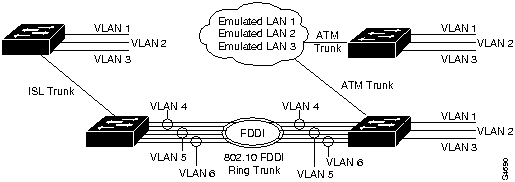
Define the VLAN, indicating the parameters described above: VLAN number, name, type, maximum transmission unit, SAID, state, ring number, bridge identification number, and number to indicate whether source routing should be set to transparent or bridging. A maximum of 100000 VLANs can be active at any time. Figure 42 shows an example of the set vlan command. Figure 43 shows a diagram of the established VLANs, illustrating how VTP can traverse trunk connections using the ISL and 802.10 protocols and ATM LAN emulation (LANE). In Figure 43, Ethernet VLAN 1 is translated to FDDI VLAN 4 on the FDDI module, Ethernet VLAN 2 is translated to FDDI VLAN 5, and so on.
set vlan vlan_num [name name] [type type] [mtu mtu] [said said] [state state] [ring ring_number] [bridge bridge_number] [parent vlan_num] [stp stp_type] [translation vlan_num]
Verify that the VLAN configuration is correct. Figure 44 shows a sample display of the show vlan command.
show vlan
Console> (enable) set vtp domain engineering mode client interval 160
VTP: domain engineering modified
Console> (enable)
Console> (enable) show vtp domain
Domain Name                    Domain Index VTP Version Local Mode
------------------------------ ------------ ----------- -----------
engineering                    1            1           client

Last Updater    Vlan-count Max-vlan-storage Config Revision Notifications
--------------- ---------- ---------------- --------------- -------------
172.20.25.130   5          256              0               disabled
Console> (enable)
Console> (enable) set vlan 3 name engineering type ethernet
VTP: vlan addition successful
Console> (enable)
Console> (enable) show vlan
VLAN Name                             Status    Mod/Ports
---- -------------------------------- --------- ----------------------------
1    default                          active    1/1-2
                                                2/1-24
2    VLAN0002                         active
3    VLAN0003                         active
5    VLAN0005                         active
1002 fddi-default                     active
1003 token-ring-default               active
1004 fddinet-default                  active
1005 trnet-default                    active


VLAN Type  SAID       MTU   Parent RingNo BridgeNo Stp  Trans1 Trans2
---- ----- ---------- ----- ------ ------ -------- ---- ------ ------
1    enet  10001      1500  -      -      -        -    1003   1002
2    enet  10002      1500  -      -      -        -    0      0
3    enet  100003     1500  -      -      -        -    0      0
5    enet  100005     1500  -      -      -        -    0      0
1002 fddi  1002       1500  0      0      -        -    1003   1
1003 tring 1003       1500  1005   4095   -        -    1      1002
1004 fdnet 33         1500  -      -      0        ieee 0      0
1005 trnet 1005       1500  -      -      15       ibm  0      0
Console> (enable)
Task
Command
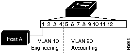
Define the VLAN and indicate the included ports. Figure 45 shows an example of the set vlan command. Figure 46 show a diagram of the established VLANs. VLAN 10, the engineering department, includes module 2, Ethernet ports 1 through 4. VLAN 20, the accounting department, includes module 2, Ethernet ports 5 through 24. The accounting and engineering departments are totally isolated from each another in this configuration.
set vlan vlan mod/ports
Verify that the VLAN configuration is correct. Figure 47 shows a sample display of the show vlan command.
show vlan
Console> (enable) set vlan 10 2/1-4
VLAN 10 modified.
VLAN 1 modified.
VLAN    Mod/Ports
10      2/1-4
Console> (enable)
Console> (enable) set vlan 20 2/5-24
VLAN 20 modified.
VLAN 1 modified.
VLAN    Mod/Ports
20      2/5-24
Console> (enable)
Console> (enable) show vlan
VLAN Name                             Status    Mod/Ports
---- -------------------------------- --------- ----------------------------
1    default                          active    1/1-2
                                                2/1-24
2    VLAN0002                         active
3    VLAN0003                         active
5    VLAN0005                         active
1002 fddi-default                     active
1003 token-ring-default               active
1004 fddinet-default                  active
1005 trnet-default                    active


VLAN Type  SAID       MTU   Parent RingNo BridgeNo Stp  Trans1 Trans2
---- ----- ---------- ----- ------ ------ -------- ---- ------ ------
1    enet  10001      1500  -      -      -        -    1003   1002
2    enet  10002      1500  -      -      -        -    0      0
3    enet  100003     1500  -      -      -        -    0      0
5    enet  100005     1500  -      -      -        -    0      0
1002 fddi  1002       1500  0      0      -        -    1003   1
1003 tring 1003       1500  1005   4095   -        -    1      1002
1004 fdnet 33         1500  -      -      0        ieee 0      0
1005 trnet 1005       1500  -      -      15       ibm  0      0
Console> (enable)
Task
Command
Establish trunks on specific ports. Set the trunk to on to make it a trunk port, off to make it a non-trunk port, desirable to make it a trunk port if the port it is connected to allows trunking, or auto to make it a trunk port if the port it is connected to becomes set for trunking. Figure 48 shows an example of the set trunk command. Port 1 on module 1 is configured as a trunk.
set trunk mod_num/port_num
[ on | off | desirable | auto ] [vlans]
Verify that the trunk configuration is correct. Figure 49 shows a sample display of the
show trunk command.
show trunk
Console> (enable) set trunk 1/2 5
Port 1/2 allowed vlans modified to 1-5.
Console> (enable) set trunk 1/1 desirable
Port 1/1 mode set to desirable.
Port 1/1 has become a trunk.
Console> (enable)
Console> (enable) show trunk
Port     Mode       Status
-------  ---------  ------------
1/1      auto       trunking
1/2      auto       not-trunking

Port     Vlans allowed
-------  ---------------------------------------------------------------------
1/1      1-1000
1/2      1-1000

Port     Vlans active
-------  ---------------------------------------------------------------------
1/1      1-3,5
1/2      1
Console> (enable)
Task
Command
Provide a VLAN number and activate a VLAN in the management domain. Refer to Figure 51 for an example. This creates a VLAN but does not assign it to a port. VTP advertises the VLAN to all available trunks of all types (such as Ethernet or FDDI) that are set to on, for all Catalyst 5000s in the same management domain.
set vlan vlan_num
Assign the VLAN to an FDDI port. Provide the VLAN number, module number, and port number. Additionally use this commend to set up the native FDDI VLAN. Refer to Figure 52 for an example.
set vlan vlan_num mod_num/port_num
Create a VLAN with type FDDI. See Figure 53 for an example.
set vlan vlan_num type fddi
Map the Ethernet VLAN translation to an FDDI VLAN. Refer to Figure 54 for an example.
set vlan ether_vlan_num translation fddi_vlan_num
set vlan fddi_vlan_num translation ether_vlan_num
Turn trunking on for the FDDI port. (See Figure 55.)
set trunk mod_num /port_num on
Verify that the VLAN configuration is correct, including the mapping between Ethernet, FDDI, and token ring. If you use the show trunk command after a 30 second delay, you will see a display of the new VLAN that have been added to all Catalyst 5000 series switches. Figure 56 shows a sample display of the show vlan command.
show vlan [trunk | no trunk ]
show trunk
Console> (enable) set vlan 33
VTP: vlan addition successful
Console> (enable)
Console> (enable) set vlan 33 2/13
VLAN 33 modified.
VLAN 1 modified.
VLAN  Mod/Ports
---- -----------------------
33    1/2
      2/13
      4/1-2
Console> (enable)
Console> (enable) set vlan 333 type fddi
VTP: vlan addition successful
Console> (enable)
Console> (enable) set vlan 33 translation 333
VTP: vlan modification successful
Console> (enable)
Console> (enable) set trunk 1/1 on
Port 1/1 mode set to on.
Console> (enable)
Console> (enable) show vlan
VLAN Name                       Type  Status    Mod/Ports
---- -------------------------- ----- --------- ----------------
1    default                    enet  active    1/1
                                                2/3-4,2/7-12,2/14-16,2/18-24
11   VLAN0011                   enet  active    2/1-2
22   VLAN0022                   enet  active    2/5-6
33   VLAN0033                   enet  active    2/13,2/17
111  VLAN0111                   fddi  active
222  VLAN0222                   fddi  active
333  VLAN0333                   fddi  active
1002 fddi-default               fddi  active
1003 token-ring-default         tring active
1004 fddinet-default            fdnet active
1005 trnet-default              trnet active


VLAN SAID       MTU   RingNo BridgeNo StpNo Parent Trans1 Trans2
---- ---------- ----- ------ -------- ----- ------ ------ ------
1    100001     1500  0      0        0     0      0      0
11   100011     1500  0      0        0     0      111    0
22   100022     1500  0      0        0     0      222    0
33   100033     1500  0      0        0     0      333    0
111  100111     1500  0      0        0     0      11     0
222  100222     1500  0      0        0     0      22     0
333  33         1500  0      0        0     0      33     0
1002 101002     1500  0      0        0     0      0      0
1003 101003     1500  0      0        0     0      0      0
1004 101004     1500  0      0        0     0      0      0
1005 101005     1500  0      0        0     0      0      0
CAT4> (debug-eng)
Console> (enable)
-s
Causes ping to send one datagram every second, printing one line of output for every response received. The ping command does not return any output when no response is received.
host
The IP address or IP alias of the host.
packet_size
(Optional) The number of bytes in a packet, from 1 to 2,000 bytes, with a default of 56 bytes. The actual packet size is eight bytes larger because the switch adds header information.
packet_count
(Optional) The number of packets to send
Console> ping elvis
elvis is alive
Console> ping -s elvis
ping elvis: 56 data bytes
64 bytes from elvis: icmp_seq=0. time=11 ms
64 bytes from elvis: icmp_seq=1. time=8 ms
64 bytes from elvis: icmp_seq=2. time=8 ms
64 bytes from elvis: icmp_seq=3. time=7 ms
64 bytes from elvis: icmp_seq=4. time=11 ms
64 bytes from elvis: icmp_seq=5. time=7 ms
64 bytes from elvis: icmp_seq=6. time=7 ms
^C
----elvis PING Statistics----
7 packets transmitted, 7 packets received, 0% packet loss
round-trip (ms)  min/avg/max = 7/8/11
Console> (enable)
Console> (enable) show system
PS1-Status PS2-Status Fan-Status Temp-Alarm Sys-Status Uptime d,h:m:s Logout
---------- ---------- ---------- ---------- ---------- -------------- ---------
ok         none       ok         off        ok         0,18:31:53     none

PS1-Type   PS2-Type   Modem   Baud  Traffic Peak Peak-Time
---------- ---------- ------- ----- ------- ---- -------------------------
WS-C5101   none       disable  9600   0%      0% Tue May 14 1996, 14:37:31

System Name              System Location          System Contact
------------------------ ------------------------ ------------------------
Console> (enable)
Console> (enable) show config
begin
set password $1$FMFQ$HfZR5DUszVHIRhrz4h6V70
set enablepass $1$FMFQ$HfZR5DUszVHIRhrz4h6V70
set prompt Console>
set length 100 default
set logout 0
!
#system
set system baud  9600
set system modem disable
set system name
set system location
set system contact
!
#snmp
set snmp community read-only      public
set snmp community read-write     private
set snmp community read-write-all secret
set snmp rmon enable
set snmp trap disable module
set snmp trap disable chassis
set snmp trap disable bridge
set snmp trap disable repeater
set snmp trap disable vtp
set snmp trap disable auth
!
#ip
set interface sc0 1 172.20.25.130 255.255.0.0 172.20.255.255

set interface sl0 0.0.0.0 0.0.0.0
set arp agingtime 1200
set ip redirect   enable
set ip unreachable   disable
set ip fragmentation enable
set ip route 0.0.0.0         172.20.1.201    1

set ip alias default         0.0.0.0
set ip alias max             171.69.193.165
set ip alias atlas           172.20.1.201
set ip alias floater         172.20.25.130
set ip alias brooks          172.20.25.132
set ip alias da_bears        172.20.22.7
set ip alias lnf             172.20.0.0
!
!
#vlan
set vlan 1    1/2,2/1-24,4/1,4/13,4/25,4/37
!
#trunks
set trunk 1/1  desirable 1-1000
set trunk 1/2  off 1-1000
.
.
.
#vlan 2
set spantree enable         2
set spantree fwddelay 15    2
set spantree hello    2     2
set spantree maxage   20    2
set spantree priority 32768 2end
!
#trunk
set spantree portcost     1/1  10
set spantree portpri      1/1  32
set spantree portvlanpri  1/1  0 100-102
set spantree portfast     1/1  disable
set spantree portcost     1/2  10
set spantree portpri      1/2  32
set spantree portvlanpri  1/2  0
set spantree portfast     1/2  disable
!
#module 1
set module name    1
set port enable    1/1-2
set port level     1/1-2  normal
set port duplex    1/1-2  half
set port trap      1/1-2  disable
set port name      1/1  Fred Flintstone
set port name      1/2
!
#module 2
set module name    2
set module enable  2
set port enable    2/1-24
set port level     2/1-24  normal
set port duplex    2/1-24  half
set port trap      2/1-24  disable
set port name      2/1-24
!
#module 3 empty
!
#module 4
set module name    4
set module enable  4
set port enable    4/1-48
set port level     4/1,4/13,4/25,4/37  normal
set port trap      4/1-48  disable
set port name      4/1-48
!
#module 5 empty
!

#switch port analyzer
set span 1 1/1  both
set span disable
end
Console> (enable)
Console> (enable) show port
Port Name                  Status     Vlan       Level  Duplex Speed Type
---- --------------------  ---------- ---------- ------ ------ ----- -----------
1/1  Management Port       connected  1          normal   half   100  100BaseTX
1/2  InterSwitch Link      connected  trunk      normal   half   100  100BaseTX
2/1  FDDI 100BaseFX        connected  1          normal   half   100  100BaseFX
2/2  10BaseFL 12 Port      connected  1          normal   half   auto 10BaseFL
2/3  10BaseFL 12 Port      connected  1          normal   half   auto 10BaseFL
2/4  10BaseFL 12 Port      connected  1          normal   half   auto 10BaseFL
2/5  10BaseFL 12 Port      connected  1          normal   half   auto 10BaseFL
.
.
.
4/45                       notconnect 1          normal   half    10  10BaseT
4/46                       notconnect 1          normal   half    10  10BaseT
4/47                       notconnect 1          normal   half    10  10BaseT

Port Align-Err  FCS-Err    Xmit-Err   Rcv-Err
---- ---------- ---------- ---------- ----------
1/1           0          0          0          0
1/2           0          0          0          0
2/1           0          0          0          0
2/2           0          0          0          0
2/3           0          0          0          0
.
.
.
2/18          0          0          0          0
2/19          0          0          0          0
2/20          0          0          0          0
2/21          0          0          0          0
2/22          0          0          0          0
2/23          0          0          0          0
2/24          0          0          0          0TT


Port Auto-Parts Giants     Data-Rate  FCS-Err    Runts      Rcv-frms   Src-Addr
                           Mismatch                                    Changes
---- ---------- ---------- ---------- ---------- ---------- ---------- --------
4/1           0          0          0          0          0          0        0
4/2           0          0          0          0          0          0        0
4/3           0          0          0          0          0          0        0
4/4           0          0          0          0          0          0        0
4/5           0          0          0          0          0          0        0
4/6           0          0          0          0          0          0        0
.
.
.
4/43          0          0          0          0          0          0        0
4/44          0          0          0          0          0          0        0
4/45          0          0          0          0          0          0        0
4/46          0          0          0          0          0          0        0
4/47          0          0          0          0          0          0        0
4/48          0          0          0          0          0          0        0


Port Rcv-Multi  Rcv-Broad  Good-Bytes Align-Err  Short-Evnt Late-Coll Collision
---- ---------- ---------- ---------- ---------- ---------- --------- ---------
4/1           0          0          0          0          0         0         0
4/2           0          0          0          0          0         0         0
4/3           0          0          0          0          0         0         0
4/4           0          0          0          0          0         0         0
.
.
.
4/42          0          0          0          0          0         0         0
4/43          0          0          0          0          0         0         0
4/44          0          0          0          0          0         0         0
4/45          0          0          0          0          0         0         0
4/46          0          0          0          0          0         0         0
4/47          0          0          0          0          0         0         0
4/48          0          0          0          0          0         0         0

Last-Time-Cleared
--------------------------
Tue May 14 1996, 14:37:31
Console> (enable)
![]()
![]()
![]()
![]()
![]()
![]()
![]()
![]()