|
|

Catalyst 5000 Series Release Notes for ATM Software Release 2.2
This release note describes the features, caveats, and modifications for the Catalyst 5000 series ATM Software Release 2.2. It contains the following sections:
Catalyst 5000 Series Documentation
The following documents are available for the Catalyst 5000 series switch:
These documents are available in printed form and in electronic form on UniverCD.
New Features in ATM Software Release 2.2
The following two modifications have been made in ATM Module Software Release 2.2:
New Features in ATM Software Release 2.1
Some commands have been changed and new commands added in ATM Module Software Release 2.1. These commands were created or modified to support LAN emulation (LANE), that is, emulated LANs (ELANs). Using a Catalyst 5000 ATM module, you can now directly set up the following client and servers:
Although the Cisco routers with ATM interfaces can still supply all LANE functions, you are no longer required to use a router to configure the LES, BUS, and LECS.
Implementation of LAN Emulation (LANE)
The implementation of LANE makes an ATM interface look like one or more Ethernet interfaces.
LANE is an ATM service defined by the ATM Forum specification "LAN Emulation over ATM," ATM_FORUM 94-0035. This service emulates the following LAN-specific characteristics:
LANE service provides connectivity between ATM-attached devices and LAN-attached devices. This includes connectivity between ATM-attached stations and LAN-attached stations, as well as connectivity between LAN-attached stations across an ATM network.
Because LANE connectivity is defined at the MAC layer, upper-protocol layer functions of LAN applications can continue unchanged when the devices join Emulated LANs (ELANs). This feature protects corporate investments in legacy LAN applications.
An ATM network can support multiple independent ELANs. Membership of an end system in any of the ELANs is independent of the physical location of the end system. This characteristic simplifies hardware moves and changes. In addition, the end systems can move easily from one ELAN to another, independent of whether the hardware moves.
In this release, Cisco supports only emulated Ethernet LANs. This release does not support emulation of Token Ring networks.
This release of LANE is supported on Catalyst 5000 series switches containing ATM modules and on Cisco routers with ATM interfaces installed; it requires an ATM switch that supports UNI 3.0 and point-to-multipoint signaling---for example, the Cisco LightStream family of ATM switches.
An unlimited number of ELANs can be set up in an ATM switch cloud. A Catalyst 5000 ATM module can participate in multiple ELANs.
LANE is defined on a client-server LAN model as follows:
The LECS contains the database that determines which ELAN a device belongs to (each configuration server can have a differently named database). Each LEC consults the LECS just once, when it joins an ELAN, to determine which ELAN it should join. The LECS returns the ATM address of the LES for that ELAN.
One LECS is required per ATM LANE switch cloud.
The LECS database can have the following four types of entries:
LANE Operation and Communication
Communication among LANE components is ordinarily handled by several types of switched virtual circuits (SVCs). Some SVCs are unidirectional; others are bidirectional. Some are point-to-point and others are point-to-multipoint. Figure 1 illustrates the various types of SVCs. In this figure, LECS stands for the LECS, and BUS stands for the LANE BUS.
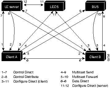
The following section describes LANE Operation and Communication processes, starting with a client requesting to join an ELAN after the component Catalyst 5000 series switches have been installed.
The following process (illustrated in Figure 1) normally occurs after a LEC has been enabled on the ATM module in a Catalyst 5000 series switch:
As communication occurs on the ELAN, each client dynamically builds a local LANE ARP (LE ARP) table. A client's LE ARP table can also have static, preconfigured entries. The LE ARP table maps MAC addresses to ATM addresses.
When a client first joins an ELAN, its LE ARP table has no dynamic entries, and the client has no information about destinations on or behind its ELAN. To learn about a destination when a packet is to be sent, the client begins the following process to find the ATM address corresponding to the known MAC address:
For unknown destinations, the client sends a packet to the BUS, which forwards the packet to all clients. The BUS floods the packet because the destination might be behind a bridge that has not yet learned this particular address.
When a LEC has broadcast or multicast traffic, or unicast traffic with an unknown address to send, the following process occurs:
On a LAN, packets are addressed by the MAC-layer addresses of the destination and source stations. To provide similar functionality for LANE, MAC-layer addressing must be supported. Every LEC must have a MAC address. In addition, every LANE component (server, client, BUS, and configuration server) must have a unique ATM address.
In this release, all LECs on the same interface have the same, automatically assigned MAC address. That MAC address is also used as the end-system identifier (ESI) part of the ATM address, as explained in the following section. Although client MAC addresses are not unique, all ATM addresses are unique.
A LANE ATM address has the same syntax as an NSAP, but it is not a network-level address. It consists of the following:
Automatically Assigning ATM Addresses
Cisco provides the following standard method of constructing and assigning ATM and MAC addresses for use in a LECS database. A pool of MAC addresses is assigned to each ATM module. The pool contains 16 MAC addresses. For constructing ATM addresses, the following assignments are made to the LANE components:
Because the LANE components are defined on different subinterfaces of an ATM interface, the value of the selector field in an ATM address is different for each component. The result is a unique ATM address for each LANE component, even within the same Catalyst 5000 series switch. For more information about assigning components to subinterfaces, see the "Rules for Assigning Components to Interfaces and Subinterfaces" section later in this chapter.
For example, if the MAC addresses assigned to an interface are 0800.200C.1000 through 0800.200C.100F, the ESI part of the ATM addresses are assigned to LANE components as follows:
Refer to the example sections "Multiple ELANs with Unrestricted Membership" and "Multiple ELANs with Restricted Membership" for examples using MAC address values as ESI field values in ATM addresses, and for examples using subinterface numbers as Selector field values in ATM addresses.
ATM address templates can be used in many LANE commands that assign ATM addresses to LANE components (thus overriding automatically assigned ATM addresses) or that link client ATM addresses to ELANs. The use of templates can greatly simplify the use of these commands. The syntax of address templates, the use of address templates, and the use of wildcard characters within an address template for LANE are very similar to those of address templates for ISO CLNS.
LANE ATM address templates can use two types of wildcards: an asterisk (*) to match any single character, and an ellipsis (...) to match any number of leading or trailing characters.
In LANE, a prefix template explicitly matches the prefix but uses wildcards for the ESI and selector fields. An ESI template explicitly matches the ESI field but uses wildcards for the prefix and selector. Table 1 indicates how the values of unspecified bytes are determined when an ATM address template is used.
Table 1 : ATM Address Template Values
| Unspecified Digits In | Value Is |
|---|---|
| Prefix (first 13 bytes) | Obtained from ATM switch via ILMI, or configured locally if ILMI is not supported on the ATM switch. |
| ESI (next 6 bytes) | Filled with the slot MAC address1 plus
|
| Selector field (last 1 byte) | Subinterface number, in the range 0 through 255. |
Rules for Assigning Components to Interfaces and Subinterfaces
The following rules apply to assigning LANE components on the major ATM interface and its subinterfaces:
The Catalyst 5000 ATM module uses ILMI registration to build its ATM address and to register this address with the ATM switch. To build its ATM address, the Catalyst 5000 obtains its ATM address prefix from the ATM switch. Then it combines the ATM address prefix with its own MAC address and the LEC subinterface number. Once the Catalyst ATM module has determined its ATM address, it uses ILMI registration to register this address with the ATM switch.
Using the atm vc-per-vp command, you can configure the maximum number of VCIs per VPI. If this value is configured, when the Catalyst 5000 ATM module registers with the ATM switch, the maximum number of VCIs per VPI is also passed to the ATM switch. In this way, the ATM switch will not assign a VCI value for an SVC to the Catalyst 5000 that is out of the ATM switch's range. The default is 10 VCI bits, and 0 VPI bits on the Catalyst 5000 ATM module. Any change from the default requires an ATM module reset.
On the Catalyst 5000 series switch, a VLAN is a logical group of end stations, independent of physical location, with a common set of requirements. Currently, the Catalyst 5000 series switch supports a port-centric VLAN configuration. All end stations connected to ports belong to the same VLAN and are assigned to the same VLAN number. The VLAN number is only significant to the Catalyst 5000 series switch.
On an ATM network, an emulated LAN is called an ELAN and is designated by a name. To create a VLAN that spans multiple Catalyst 5000 series switches on an ATM network, you must assign the VLAN on each Catalyst 5000 series switch to the same ELAN. Use the lane client ethernet vlan# elan-name command to link the VLAN number with the ELAN name. You must use a router to allow communication between two or more ELANs, whether they are on the same or on different Catalyst 5000 series switches.
In typical LANE cases, one or more Catalyst 5000 series switches or Cisco routers with ATM interfaces are attached to a Cisco LightStream ATM switch. For distributing multiple ELANs within a network, you can use Catalyst 5000 switches instead of Cisco routers with ATM interfaces to configure the LECS (LECS), LANE server (LES), and LANE BUS.
The physical layout and the physical components of an emulated network might not differ for the single and the multiple ELAN cases. The differences are in the software configuration for the number of ELANs and the assignment of LANE components to the different physical components.
LANE Scenarios with Catalyst 5000 Switches Only
In typical LANE cases using Catalyst 5000 series switches only, one or more Catalyst 5000 series switches are attached to a Cisco LightStream ATM switch. The Cisco LightStream ATM switch provides connectivity to the broader ATM network switch cloud. The Catalyst 5000 series switches are configured to support one or more ELANs. One of the Catalyst 5000 series switches is configured to perform the LECS functions. Another Catalyst 5000 series switch is configured to perform the server function and the BUS function for each ELAN. (One Catalyst 5000 series switch can perform the server and the BUS functions for several ELANs.) A Catalyst 5000 series switch can act as a LEC for one or more ELANs.
This section presents two scenarios using Catalyst 5000 series switches and a Cisco LightStream ATM switch. Figure 2 illustrates the use of four Catalyst 5000 series switches and one Cisco LightStream ATM switch; it illustrates both the single and the multiple ELAN cases.
Figure 2 : ELAN Layout with Catalyst 5000 Switches Only
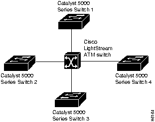
Single ELAN Scenario with Catalyst 5000 Switches Only
In a single ELAN scenario, the LANE components might be assigned as follows:
Multiple ELAN Scenario with Catalyst 5000 Switches Only
In the multiple LAN scenario, one ATM switch and four Catalyst 5000 series switches are used, but multiple ELANs are configured. In the following scenario, three ELANs are configured on the four Catalyst 5000 series switches.
The LANE components are assigned as follows:
LANE Scenarios with Catalyst 5000 Switches and Routers
LANE configurations that use routers typically have one or more Catalyst 5000 series switches or Cisco routers with ATM interfaces attached to a Cisco LightStream ATM switch. The Cisco LightStream ATM switch provides connectivity to the broader ATM network switch cloud. The routers are configured to support one or more ELANs. One of the routers is configured to perform the LECS functions. A router is configured to perform the server function and the BUS function for each ELAN. (One router can perform the server and the BUS functions for several ELANs.) Routers and Catalyst 5000 series switches can act as a LEC for one or more ELANs.
This section presents two scenarios using a router, Catalyst 5000 series switches, and a Cisco LightStream ATM switch. Figure 3 illustrates this typical layout of one Cisco LightStream ATM switch, with a Cisco router and three Catalyst 5000 series switches; it illustrates both the single and the multiple ELAN cases.
Figure 3 : Typical ELAN Layout
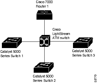
Single ELAN Scenario with Catalyst 5000 Switches and Routers
In a single ELAN scenario, the LANE components might be assigned as follows:
Refer to the "Default Configuration for a Single ELAN" section for an illustrated example of this scenario.
Multiple ELAN Scenario with Catalyst 5000 Switches and Routers
In a multiple LAN scenario, one ATM switch, one router, and three Catalyst 5000 series switches are used, but multiple ELANs are configured. In the following scenario, three ELANs are configured on a router and three Catalyst 5000 series switches. Refer to the example sections "Multiple ELANs with Unrestricted Membership" and "Multiple ELANs with Restricted Membership" for detailed examples.
The LANE components are assigned as follows:
Before you begin to configure LANE, you must decide whether you want to set up one or multiple ELANs and, if multiple, where the servers and clients will be located, and whether to restrict the clients that can belong to each ELAN. Once you have made those basic decisions, you can proceed to configure LANE. Some of the tasks required to configure LANE are performed on a Cisco LightStream ATM switch.
The following sections describe the tasks required to configure LANE:
![]()
You can configure some ELANs from a router and some from a Catalyst 5000 switch. You can configure some ELANs with unrestricted membership and some ELANs with restricted membership. You can also configure a default ELAN, which must have unrestricted membership.
Once LANE is configured, you can monitor and maintain the components in the participating Catalyst 5000 ATM modules and optional routers by completing the tasks in the "Monitor and Maintain the LANE Components" section.
Create a LANE Plan and Worksheet
It might help you to begin if you draw up a plan and a worksheet for your own LANE scenario; include the following information, and leave space for the ATM address of each LANE component on each subinterface of each participating device. The last three items in this list are very important; they determine how you set up each ELAN in the configuration server's database:
Configure the Prefix on a Cisco LightStream ATM Switch
Before you configure LANE components on Catalyst 5000 switches, you must configure a Cisco LightStream ATM switch with the ATM address prefix to be used by all LANE components in the switch cloud.
To set the ATM address prefix, complete the following steps on the Cisco LightStream ATM switch:
| Task | Command |
|---|---|
| Set the local node ID (prefix of the ATM address). | set local name ip-address mask prefix1 |
| Save the configuration values permanently. | save |
On the Cisco LightStream ATM Switch, you can display the current prefix by using the show network command.
Set Up and Display Addresses for LESs and Clients
For each Catalyst 5000 series switch that will participate in LANE, set up the necessary clients for each ELAN; then display and record the client ATM addresses. Be sure to keep track of the Catalyst 5000 series switch or router interface where the LECS will eventually be located.
If you are going to have only one default ELAN, you will have only one server to set up. If you are going to have multiple ELANs, you can set up the server for another ELAN on a different subinterface on the same interface of this router---or you can place it on a different Catalyst 5000 switch.
To set up only a client on a subinterface, complete the steps in the "Set Up the Signaling and ILMI PVCs" section and the "Set Up Only a Client on a Subinterface" section.
Client location is important, because any router with clients for multiple ELANs can route frames between those ELANs.
To set up the server, BUS, and a client on the same subinterface, complete the steps in the following sections:
To set up only a client on a subinterface, complete the steps in the following sections:
Once you have set up the components, you can display their ATM addresses by completing the task in the "Display the Client ATM Addresses" section.
Set Up the Signaling and ILMI PVCs
Set up the signaling and the ILMI PVC that will communicate with the ILMI on the major ATM interface of any Catalyst 5000 series switch that will participate in LANE. Complete this task only once for a major interface. You do not need to repeat this task on the same interface even though you might configure LECs on several of its subinterfaces.
To set up these PVCs, complete the following tasks, beginning in global configuration mode:
| Task | Command |
|---|---|
| |
interface atm 0 |
| |
atm pvc vcd vpi vci qsaal1 |
| |
atm pvc vcd vpi vci ilmi |
Set Up the Server, BUS, and a Client on a Subinterface
To set up the server and broadcast-and-unknown server (BUS) for an ELAN, perform the following steps beginning in interface configuration mode:
| Task | Command |
|---|---|
| |
interface atm 0.subinterface-number |
| |
lane server-bus ethernet elan-name |
| |
lane client ethernet [vlan-1] [elan-name] |
If the ELAN in Step 3 is intended to have restricted membership, consider carefully whether you want to specify its name here. You will specify the name in the LECS database when it is set up. However, if you link the client to an ELAN in this step and, through some mistake, it does not match the database entry linking the client to an ELAN, this client will not be allowed to join this ELAN or any other. You might consider this as either a helpful check that the configuration is correct, or as a problem to overcome.
If you do decide to include the name of the ELAN linked to the client in Step 3 and later want to associate that client with a different ELAN, make the change in the configuration server's database before you make the change for the client on this subinterface.
Set Up Only a Client on a Subinterface
On any given Catalyst 5000 series switch, you can set up one client for one ELAN or multiple clients for multiple ELANs. You can set up a client for a given ELAN on any Catalyst 5000 you choose to have participate in that ELAN. After you set up the interface for the VLAN, you must link the VLAN number with the ELAN name.
You must first set up the signaling and ILMI PVCs on the major ATM interface, as described earlier in the "Set Up the Signaling and ILMI PVCs" section, before you set up the client.
To set up only a client for an ELAN, perform the following steps---beginning in interface configuration mode:
| Task | Command |
|---|---|
| |
interface atm 0.subinterface-number |
| |
lane client ethernet vlan# elan-name |
Display the Client ATM Addresses
Once you have set up the clients as needed on the subinterfaces of an ATM module on the Catalyst 5000 series switch, you can display their ATM addresses by completing the following step in EXEC mode:
| Task | Command |
|---|---|
| Display the server, BUS, and client ATM addresses. | show lane |
The output of this command shows all subinterfaces configured for LANE. For each subinterface, the command displays and clearly labels the ATM addresses that belong to the server, the BUS, and the client.
When you look at each ATM address, you will notice the following:
This automatic assignment of ATM address values was explained in the section "Automatically Assigning ATM Addresses," earlier in this chapter.
Repeat the show lane step on each Catalyst 5000 series switch before you proceed to set up the clients on the next Catalyst 5000.
Print the display (or make a note on your LANE worksheet of these ATM addresses) so you can use it when you set up the configuration server's database.
At this point, the clients will not yet be operational. That is normal for this stage of LANE configuration.
Set Up the Configuration Server's Database
After you have set up all the servers, BUSs, and clients on all the ATM subinterfaces on all Catalyst 5000 series switches or routers that will participate in LANE and have displayed their ATM addresses, you can use the information to populate the configuration server's database.
You can set up a default ELAN, no matter whether you set up any other ELANs. You can also set up some ELANs with restricted membership and others with unrestricted membership.
To set up the database, complete the steps in the following sections as appropriate for your ELAN plan and scenario:
Set Up the Signaling and ILMI PVCs
If you have already set up the signaling and ILMI PVCs on this interface, skip to the next section.
You must set up the signaling PVC and the PVC that will communicate with the ILMI on the major ATM interface of any router that will participate in LANE.
Complete this task only once for a major interface. You need not repeat this task on the same interface, even though you might configure LESs and clients on several of its subinterfaces.
To set up these PVCs, complete the following steps, beginning in global configuration mode:
| Task | Command |
|---|---|
| |
interface atm 0 |
| |
atm pvc vcd vpi vci qsaal1 |
| |
atm pvc vcd vpi vci ilmi1. |
Set Up the Database for the Default ELAN Only
When you configure a Catalyst 5000 switch as the configuration server for one default ELAN, you provide a name for the database, the ATM address of the server for the ELAN, and a default name for the ELAN. In addition, you indicate that the configuration server's ATM address is to be computed automatically.
When you set up a database of only a default, unrestricted ELAN, you need not specify where the LANE clients are located. That is, when you set up the configuration server's database for a single default ELAN, you need not provide any database entries that link the ATM addresses of any clients with the ELAN name.
To set up the configuration server for the default ELAN, complete the following steps beginning in global configuration mode:
| Task | Commands |
|---|---|
| |
lane database database-name |
| |
name elan-name server-atm-address atm-address |
| |
default-name elan-name |
| |
exit |
In Step 2, enter the ATM address of the server for the specified ELAN as noted in your worksheet.
If you are setting up only a default ELAN, the elan-name value in Step 2 is the same as the default ELAN name you provide in Step 3.
Set Up the Database for Unrestricted-Membership ELANs
When you set up a database for unrestricted ELANs, you create database entries that link the name of each ELAN to the ATM address of its server.
However, you may choose not to specify where the LANE clients are located. That is, when you set up the configuration server's database, you do not have to provide any database entries that link the ATM addresses or MAC addresses of any clients with the ELAN name.
To configure a router as the configuration server for multiple ELANs with unrestricted membership, complete the following steps beginning in global configuration mode:
| Task | Command |
|---|---|
| |
lane database database-name |
| |
name elan-name1 server-atm-address atm-address |
|
name elan-name2 server-atm-address atm-address |
| |
default name elan-name |
| |
exit |
In Steps 2 and 3, enter the ATM address of the server for the specified ELAN, as noted in your worksheet.
Set Up the Database for Restricted-Membership LANs
When you set up the database for restricted-membership ELANs, you create database entries that link the name of each ELAN to the ATM address of its server.
However, you also must specify where the LECs are located. That is, for each restricted-membership ELAN, you provide a database entry that explicitly links the ATM address or MAC address of each client of that ELAN with the name of that ELAN.
Those client database entries specify the clients that are allowed to join the ELAN. When a client requests that the configuration server indicate which ELAN it is to join, the configuration server consults its database and then responds as configured.
When clients for the same restricted-membership ELAN are located in multiple Catalyst 5000 ATM modules, each client's ATM address or MAC address must be linked explicitly with the name of the ELAN. As a result, you must configure as many client entries (Step 5 in the following procedure) as you have clients for ELANs in all the ATM modules of Catalyst 5000 switches. Of course, each client will have a different ATM address in the database entries.
To set up the configuration server for ELANs with restricted membership, perform the following tasks beginning in global configuration mode:
| Task | Command |
| |
lane database database-name |
| |
name elan-name1 server-atm-address atm-address restricted |
|
name elan-name2 server-atm-address atm-address [restricted] |
| |
default name elan-name |
|
client-atm-address atm-address name elan-name |
| |
exit |
Enable and Display the ATM Address of the Configuration Server
Once you have created the database entries as appropriate to the type and the membership conditions of the ELANs, you can enable the configuration server on the selected ATM interface and Catalyst 5000 ATM module, and then display its ATM address by completing the following tasks:
| Task | Command |
|---|---|
| |
interface atm 0 |
| |
lane config database-name |
| |
lane auto-config-atm-address |
| |
exit |
| |
Ctrl-Z |
| |
show lane config |
Make a note of the configuration server's ATM address so you can configure it on each ATM subinterface where a server and BUS is configured.
Enter the Configuration Server's ATM Address on a Cisco LS100 ATM Switch
You must enter the configuration server's ATM address into the Cisco LS100 ATM switch, and save it permanently, so that the value will not be lost when the switch is reset or powered off.
To enter the configuration server's ATM address into the Cisco LS100 ATM Switch and save it there permanently, complete the following steps on the Cisco LS100 ATM Switch:
| Task | Command |
|---|---|
| |
set configserver 0 atm-address |
| |
save |
In Step 1, you must specify the full 40-digit ATM address.
Monitor and Maintain the LANE Components
After configuring LANE components on an interface or any of its subinterfaces, on a specified subinterface, or on an ELAN, you can display their status. To show LANE information, perform the following tasks in EXEC mode:
| Task | Command |
|---|---|
| Display the global and per-VCC LANE information for all the LANE components and ELANs configured on an interface or any of its subinterfaces. | show lane [interface atm 0 [.subinterface-number] | name elan-name] [brief] |
| Display the global and per-VC LANE information for the BUS configured on any subinterface or ELAN. | show lane bus [interface atm 0 [.subinterface-number] | name elan-name] [brief] |
| Display the global and per-VC LANE information for all LANE clients (LECs) configured on any subinterface or ELAN. | show lane client [interface atm 0 [.subinterface-number] | name elan-name] [brief] |
| Display the global and per-VC LANE information for the configuration server configured on any interface. | show lane config [interface atm 0] |
| Display the LANE configuration server (LECS) database. | show lane database [database-name] |
| Display the LANE ARP table of the LANE client (LECs) configured on the specified subinterface or ELAN. | show lane le-arp [interface atm 0 [.subinterface-number] | name elan-name] |
| Display the global and per-VC LANE information for the LES configured on a specified subinterface or ELAN. | show lane server [interface atm 0 [.subinterface-number] | name elan-name] [brief] |
QuickStart Configuration Procedure
This section provides a specific operating example of how to set up a single ATM ELAN (LANE) and configure the LAN Emulation components. Substitute your own values in each step to configure the LANE module in your system. This procedure includes the following tasks:
The example below assumes you have:
Define Values for Configuring the LANE Module
Configure the ATM Address Prefix on a Cisco LS100 ATM Switch
Configure the default LS100 ATM address prefix of all edge devices connected to the switch. If you do not intend to connect the LS100 ATM switch to the Ethernet network, use After you assign an IP address to the supervisor engine module's sc0 interface, start a session with the ATM module on the console for the Catalyst 5000 as follows. The following example assumes the ATM module is in slot 5.
Set Up the Signaling and ILMI Permanent Virtual Circuits
Set up the signaling and ILMI permanent virtual circuits (PVCs) by typing the following commands:
Display the Default LANE Module Network Service Access Points
Display the default ATM network service access points (NSAPs):
Set Up the Cisco LS100 ATM Switch with the Default LECS Address
To set up the Cisco LS100 ATM switch with the default LECS address, perform the steps below:
Set Up the LECS, LES, and BUS Servers
This section describes how to set up the LAN emulation configuration server (LECS), LAN emulation server (LES), and the broadcast and unknown server (BUS).
Set Up the LAN Emulation Client
The examples in the sections below illustrate how to configure LANE for the following cases:
All examples use the automatic ATM address assignment method described in the section "Automatically Assigning ATM Addresses" earlier in these chapters.
These examples show the resulting configuration, not the process of determining and entering the ATM addresses appropriately, as described earlier.
Default Configuration for a Single ELAN
The following example configures one Cisco router and three Catalyst 5000 series switches for one ELAN. Router 1 contains the configuration server, the server, the broadcast-and-unknown server, and a client. The remaining Catalyst 5000 series switches each contain a client for the ELAN. This example accepts all default settings that are provided. For example, it does not explicitly set ATM addresses for the different LANE components that are co-located on Catalyst 5000 series switch 1. Membership in this LAN is not restricted.
Catalyst 5000 Series Switch 1
Catalyst 5000 Series Switch 2
Catalyst 5000 Series Switch 3
Catalyst 5000 Series Switch 4
Multiple ELANs with Unrestricted Membership
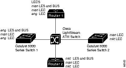
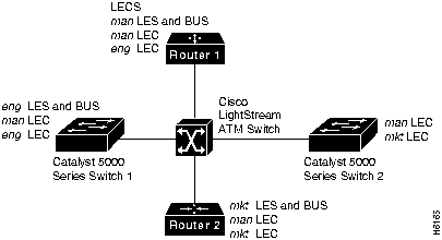
The following example configures two Cisco routers and two Catalyst 5000 series switches for three ELANS for engineering, manufacturing, and marketing, as illustrated in Figure 4. This example does not restrict membership in the ELANs.
In this example, Router 1 has the following LANE components:
Router 2 has the following LANE components:
Catalyst 5000 series switch 1 has the following LANE components:
Catalyst 5000 series switch 2 has the following LANE components:
For the purposes of this example, the Catalyst 5000 series switches and routers are assigned the following ATM address prefixes and base ESI:
Router 1
Router 1 has the configuration server and its database, the server and BUS for the manufacturing ELAN, a client for manufacturing, and a client for engineering. Router 1 is configured as follows:
Router 2
Router 2 has the server and BUS for the marketing ELAN, a client for marketing, and a client for manufacturing. Because the default ELAN name is man, the second client is linked to that ELAN name by default. Router 2 is configured as follows:
Catalyst 5000 Series Switch 1
Catalyst 5000 series switch 1 is configured for the server and BUS for the engineering ELAN, a client of the manufacturing ELAN, and a client of the engineering ELAN. Because the default ELAN name is man, the first client is linked to that ELAN name by default.
Catalyst 5000 Series Switch 2
Catalyst 5000 series switch 2 is configured for a client of the manufacturing ELAN and a client of the marketing ELAN. Because the default ELAN name is man, the first client is linked to that ELAN name by default.
Multiple ELANs with Restricted Membership
The following example, illustrated in Figure 5, configures the Cisco router for three ELANS for engineering, manufacturing, and marketing.
The same components are assigned to the four routers as in the previous example. The ATM address prefixes and MAC addresses are also the same as in the previous example.
However, this example restricts membership in the ELANs. In this example, the LECS database has explicit entries binding the ATM addresses of LECs to specified, named, ELANs. In such cases, the client asks the configuration server which ELAN it belongs to; the configuration server checks its database and informs the client to which ELAN it belongs.
Figure 5 : Multiple ELANs with Restricted Membership
Router 1
Router 1 has the configuration server and its database, the server and BUS for the manufacturing ELAN, a client for manufacturing, and a client for engineering. It also has explicit database entries binding the ATM addresses of LECs to specified, named ELANs. Router 1 is configured as follows:
Router 2
Router 2 has the server and BUS (BUS) for the marketing ELAN, a client for marketing, and a client for manufacturing. The first client is listed in the database as linked to the mkt ELANs. The second client is not listed in the database, but is linked to the man ELAN name by default. Router 2 is configured as follows:
Catalyst 5000 Series Switch 1
Catalyst 5000 series switch 1 is configured for the server and BUS for the engineering ELAN, a client of the manufacturing ELAN, and a client of the engineering ELAN. Because the default ELAN name is man, the first client is linked to that ELAN name by default.
Catalyst 5000 Series Switch 2
Catalyst 5000 series switch 2 is configured for a client of the manufacturing ELAN and a client of the marketing ELAN. Because the default ELAN name is man, the first client is linked to that ELAN name by default. The second client is listed in the database as linked to the mkt ELAN.
Configuring VPI and VCI Bits on an LS100 Switch
On an LS100, configure the valid VPI and VCI bits for the ports to which a Catalyst 5000 ATM module is connected by entering the following commands:
This command sets the valid VPI bits to 0 and valid VCI bits to 10, to match the default settings on the Catalyst 5000 ATM module.
ATM Module Software Caveats and Modifications
This section describes possible, unexpected behavior and other miscellaneous caveats for ATM module software releases. The caveats listed here describe only serious problems. This section also describes ATM module software modifications that correct caveats in earlier ATM module software versions.
ATM Module Software Version 2.2 Modifications
This section describes possible, unexpected behavior and other miscellaneous caveats for ATM module software version 2.2. Caveats existing in ATM module software version 1.1 and not resolved in versions 1.2, 1.3, or 2.1 are also present in ATM module software version 2.2. The caveats listed here describe only serious problems.
The LEC has been modified; the control distribute virtual circuit (VC) is now optional. Additionally, the LEC does not accept the VC after processing a "join" response. When the control or multicast VC does not come up due to an incorrect B-LLI (Broadband Low Layer Information) or wrong calling party, the LEC removes all associated VCs and returns to the IDLE state. (CSCdi43013)
ATM Module Software Version 2.1 Modifications
This section describes possible, unexpected behavior and other miscellaneous caveats for ATM module software version 2.1. Caveats existing in ATM module software version 1.1 and not resolved in versions 1.2 or 1.3 are also present in ATM module software version 2.1. The caveats listed here describe only serious problems. This section also describes ATM module software version 2.1 modifications that correct caveats in earlier ATM module software versions.
New Features for ATM Module Software Version 1.3
ATM Module Software Version 1.3 contains improved startup system diagnostics for manufacturability.
ATM Module Software Version 1.2 Modifications
This section describes ATM module software version 1.2 modifications that correct caveats in ATM module software version 1.1.
ATM Module Software Version 1.1 Caveats
This section describes possible, unexpected behavior and other miscellaneous caveats for ATM module software version 1.1. The caveats listed here describe only serious problems.
Cisco Connection Online (CCO), formerly Cisco Information Online (CIO), is Cisco Systems' primary, real-time support channel. Maintenance customers and partners can self-register on CCO to obtain additional content and services.
Available 24 hours a day, 7 days a week, CCO provides a wealth of standard and value-added services to Cisco's customers and business partners. CCO services include product information, software updates, release notes, technical tips, the Bug Navigator, configuration notes, brochures, descriptions of service offerings, and download access to public and authorized files.
CCO serves a wide variety of users through two interfaces that are updated and enhanced simultaneously---a character-based version and a multimedia version that resides on the World Wide Web (WWW). The character-based CCO supports Zmodem, Kermit, Xmodem, FTP, Internet e-mail, and fax download options, and is excellent for quick access to information over lower bandwidths. The WWW version of CCO provides richly formatted documents with photographs, figures, graphics, and video, as well as hyperlinks to related information.
You can access CCO in the following ways:
For a copy of CCO's Frequently Asked Questions (FAQ), contact
Copyright 1988-1996 © Cisco Systems Inc.
39000000000000000000000000
one
.
test
.
5
.
ATMSW
.
1
.
0.0.0.0
as the IP address and
255.255.255.255
as the network mask.
ATMSW>enable

Input the password:

ATMSW>#set local ATMSW IP address mask 39000000000000000000000000
Catalyst 5000> session 5
ATM>en
ATM#config terminal

ATM(config)#int atm 0

ATM(config-if)#atm pvc 1 0 5 qsaal

ATM(config-if)#atm pvc 2 0 16 ilmi

ATM(config-if)#end
ATM#show lane default-atm-addresses
interface ATM1/0:

LANE Client:         39.000000000000000000000000.00000C302A3C.**

LANE Server:         39.000000000000000000000000.00000C302A3D.**

LANE Bus:            39.000000000000000000000000.00000C302A3E.**

LANE Config Server:  39.000000000000000000000000.00000C302A3F.00
note: ** is the subinterface number byte, in hex
ATMSW
#
set configserver 0
3900000000000000000000000000000C302A3F00
0
after the configserver command is the index into the LECS address table in the ATM switch. The switch can accommodate up to four LECS addresses: index
0
through
3
.
ATMSW#
save
ATM#
config terminal

ATM(config)#
lane database test

ATM(lane-config-database)#
name one server-atm-address
  39.000000000000000000000000.00000C302A3D.01

ATM(lane-config-database)#
default-name one
test
.
server-atm-address
is the one displayed in the command above. For the last byte, use the subinterface number (
config-subif
) you plan to use in Step 3, below.
one
. (See Step 2 in the section "Set Up the LAN Emulation Client," below.)
ATM(config)#
int atm 0

ATM(config-if)#
lane config test

ATM(config-if)#
lane auto-config-atm-address
ATM(config-if)#
int atm 0.1

ATM(config-subif)#
lane server-bus ethernet one
ATM(config-subif)#
end

ATM#
wr mem
C5000>(enable)
session 5
sc0
interface before running the session command.
ATM>
enable

ATM#
config terminal

ATM(config)#
int atm 0

ATM(config-if)#
no shutdown

ATM(config-if)#
atm pvc 1 0 5 qsaal

ATM(config-if)#
atm pvc 2 0 16 ilmi

ATM(config-if)#
int atm 0.1

ATM(config-subif)#
lane client ethernet 1 one
one
, so you can omit it from the command above. However, you must provide the ELAN name if you are joining an ELAN that has not been designated as the default ELAN. The default was set up in Step 1 in the "Set Up the Signaling and ILMI Permanent Virtual Circuits" section.
lane client ethernet
vlan_#
elan_name
named
one
.
ATM(config-subif)#
end
ATM#
wr mem
lane database example1
name eng server-atm-address 39.0000014155551211.0800200c1001.01
default-name eng
interface atm 0
atm pvc 1 0 5 qsaal
atm pvc 2 0 16 ilmi
lane auto-config-atm-address
lane config example1
interface atm 0.1
lane server-bus ethernet eng
lane client ethernet 1
interface atm 0
atm pvc 1 0 5 qsaal
atm pvc 2 0 16 ilmi
interface atm 0.1
lane client ethernet 1
interface atm 0
atm pvc 1 0 5 qsaal
atm pvc 2 0 16 ilmi
interface atm 0.1
lane client ethernet 1
interface atm 0
atm pvc 1 0 5 qsaal
atm pvc 2 0 16 ilmi
interface atm 0.1
lane client ethernet 1
Router
ATM Address Prefix
ESI Base
Router 1
39.0000014155551211
0800.200c.1000
Catalyst 5000 series switch 1
39.0000014155551211
0800.200c.20001
Catalyst 5000 series switch 2
39.0000 014155551211
0800.200c.30001.
Router 2
39.0000014155551211
0800.200c.4000
1 The ESI part of the ATM address is derived from the first MAC address of the Catalyst 5000 ATM module shown in the example.
!The following lines name and configure the configuration server's database.
lane database example2
name eng server-atm-address 39.0000014155551211.0800200c2001.02
name man server-atm-address 39.0000014155551211.0800200c1001.01
name mkt server-atm-address 39.0000014155551211.0800200c4001.01
default-name man
!
! The following lines bring up the configuration server and associate
! it with a database name.
interface atm 1/0
atm pvc 1 0 5 qsaal
atm pvc 2 0 16 ilmi
lane auto-config-atm-address
lane config example2
!
! The following 3 lines configure the manufacturing server, broadcast-and-unknown server,
! and the client on atm subinterface 1/0.1. The client is assigned to the default
! emulated lan.
interface atm 1/0.1
ip address 172.16.0.1 255.255.255.0
lane server-bus ethernet man
lane client ethernet
!
! The following 3 lines configure the "eng" client on atm subinterface 1/0.2. The client
! is assigned to the engineering emulated lan. Each emulated LAN is a different
! subnetwork, so the "eng" client has an IP address on a different subnetwork than the
! "man" client.
interface atm 1/0.2
ip address 172.16.1.1 255.255.255.0
lane client ethernet eng
interface atm 3/0
atm pvc 1 0 5 qsaal
atm pvc 2 0 16 ilmi
interface atm 3/0.1
lane server-bus ethernet mkt
lane client ethernet mkt
interface atm 3/0.2
lane client ethernet
interface atm 0
atm pvc 1 0 5 qsaal
atm pvc 2 0 16 ilmi
interface atm 0.1
lane client ethernet 1
interface atm 0.2
lane server-bus ethernet eng
lane client ethernet 2 eng
interface atm 0
atm pvc 1 0 5 qsaal
atm pvc 2 0 16 ilmi
interface atm 0.1
lane client ethernet 1
interface atm 0.2
lane client ethernet 3 mkt
! The following lines name and configure the configuration server's database.
lane database example3
name eng server-atm-address 39.0000014155551211.0800200c2001.02 restricted
name man server-atm-address 39.0000014155551211.0800200c1001.01
name mkt server-atm-address 39.0000014155551211.0800200c4001.01 restricted
default-name man
!
! The following lines add database entries binding specified client ATM
! addresses to emulated LANs. In each case, the Selector byte corresponds
! to the subinterface number on the specified router.
! The next command binds the client on Router 1's subinterface 2 to the eng ELAN.
client-atm-address 39.0000014155551211.0800200c1000.02 name eng
! The next command binds the client on Router 2's subinterface 2 to the eng ELAN.
client-atm-address 39.0000014155551211.0800200c2000.02 name eng
! The next command binds the client on Router 3's subinterface 2 to the mkt ELAN.
client-atm-address 39.0000014155551211.0800200c3000.02 name mkt
! The next command binds the client on Router 4's subinterface 1 to the mkt ELAN.
client-atm-address 39.0000014155551211.0800200c4000.01 name mkt
!
! The following two lines bring up the configuration server and associate
! it with a database name.
interface atm 1/0
atm pvc 1 0 5 qsaal
atm pvc 2 0 16 ilmi
lane auto-config-atm-address
lane config example3
!
! The following 3 lines configure the "man" server/broadcast-and-unknown server,
! and the client on atm subinterface 1/0.1. The client is assigned to the default
! emulated lan.
interface atm 1/0.1
ip address 172.16.0.1 255.255.255.0
lane server-bus ethernet man
lane client ethernet
!

! The following 3 lines configure the "eng" client on atm subinterface 1/0.2. The
! configuration server assigns the client to the engineering emulated lan.
interface atm 1/0.2
ip address 172.16.1.1 255.255.255.0
lane client ethernet eng
interface atm 3/0
atm pvc 1 0 5 qsaal
atm pvc 2 0 16 ilmi
! The first client is explicitly entered in the configuration server's
! database as linked to the "mkt" ELAN.
interface atm 3/0.1
ip address 172.16.2.4 255.255.255.0
lane server-bus ethernet mkt
lane client ethernet mkt
! The following client is not entered in the database, so it is linked to the
! "man" ELAN by default.
interface atm 3/0.2
ip address 172.16.0.4 255.255.255.0
lane client ethernet
interface atm 0
atm pvc 1 0 5 qsaal
atm pvc 2 0 16 ilmi
interface atm 0.1
lane client ethernet 1
! A client for the following interface is entered in the configuration
! server's database as linked to the "eng" ELAN.
interface atm 0.2
lane server-bus ethernet eng
lane client ethernet 2 eng
interface atm 0
atm pvc 1 0 5 qsaal
atm pvc 2 0 16 ilmi
! The first client is not entered in the database, so it is linked to the
! "man" ELAN by default.
interface atm 0.1
lane client ethernet 1
! The second client is explicitly entered in the configuration server's
! database as linked to the "mkt" ELAN.
interface atm 0.2
lane client ethernet 3 mkt
ls100# set int ?

<Line>         Line number 0-15

<Inf_Type>     pri_UNI(0) , pri_NNI(1) or pub_UNI(2)

<Forum/ITU>    Forum(0) or ITU(1)

<VVP>          Valid VPI 0-12 bit(s)

<VVC>          Valid VCI 0-12 bit(s)

<LBO>          Line Built Out 0-225feet(1) or 225-450feet(0)

<PLCP>         PLCP(0) or Direct Mapping(1)

<Scramble>     Payload_Not_Scrambled(0) or Payload_Scrambled(1)

ls100# set int Catalyst_5000_ATM_port_num 0 0 0 10 1 1 1
Console> (enable) show cam dynamic 4/301

Module 4 Port number must be in the range 1..1   (CSCdi44444)
http://www.cisco.com.
cco.cisco.com.
ccohelp@cisco.com.
For additional information, contact
ccoteam@cisco.com.
tac@cisco.com.
To obtain general information about Cisco Systems, Cisco products, or upgrades, contact 800 553-6387, 408 526-7208, or
csrep@cisco.com.
![]()
![]()
![]()
![]()
![]()
![]()
![]()
![]()