|
|
This chapter provides a description of the common equipment hardware modules that make up AXIS Release 3.0. The optional service modules are described in Chapter 4.
The common equipment of the AXIS shelf consists of the following modules;
AXIS is a 19" rack mountable shelf which provides 16 slots for holding the modules (card sets) that provide the AXIS functionality. Each slot is designed to house 2 cards; a front card and a back card. Cards are installed in a slot as a two card set referred to as a module. A backplane runs across all 16 slots which provides signal connections between front and back cards and between slots. The backplane also provides power distribution to all slots from dual (redundant) power entry modules installed in the bottom of the shelf.
All external line connections (e.g., Frame Relay lines, the ATM trunk line and control console RS-232 lines) are made on the back cards at the rear of the shelf.
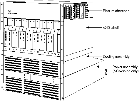
A cooling assembly containing the AXIS cooling fans consists of a rack mounted fan unit below the main AXIS shelf and either a plenum or spacer unit which is mounted above the shelves. The cooling assembly is capable of cooling up to two AXIS shelves in the same rack. In racks that contain more than two shelves, a booster cooling unit is used to provide additional cooling. The cooling assembly is powered from the main AXIS shelf. An external view of a single AXIS shelf configuration is shown in Figure 2-1. The arrangement of assemblies in a rack including cases for multiple AXIS shelves is provided in Chapter 6, Installation and Start-up.
Figure 2-1 : AXIS Shelf Configuration
An AXIS shelf consists of various kinds of modules with each module consisting of a larger front card function module which provides the functionality of the module and a smaller back card which provides the connectors and interfaces for the external lines that the module supports.
The AXIS Shelf Controller (ASC) is the module that provides the overall control of the shelf. Each AXIS shelf must have at least one ASC and may be configured with a second (redundant) ASC.
The ASC back card also provides the RS-232 ports and Ethernet port for attaching a control terminal or workstation.
The Broadband Network Module (BNM) provides the interface to the StrataCom BPX network over a T3 or E3 line using the ATM STI protocol. Each AXIS shelf must have at least one BNM and may be configured with a second (redundant) BNM. The BNM also provides:
The Service Resource Module (SRM) communicates with all service modules over a Bit Error Rate Test (BERT) bus and provides the capability for testing T1 and E1 and subrate service module lines. The SRM can set up loopback configurations and generate test bit patterns for any user specified Nx64 kbps port. The SRM can also provide 1:N redundancy for FRSM, AUSM, and CESM cards. The SRM is an optional card.
The Service Modules provide the customer interfaces. In Release 3.0, up to ten service modules may be configured in a shelf. Service modules may be intermixed in the same shelf.
The overall operation of the shelf is to:
The Inverse Multiplexing for ATM Trunk Module (IMATM), an extension to the BPX BNI card, is housed in the AXIS shelf in a service module slot and supports BPX ATM trunks over multiple (up to 8) T1 and E1 lines instead of single T3 or E3 line. The IMATM does not use the AXIS cellbus as other service modules do, but provides its own trunk to the BPX.
In performing these functions, AXIS collects a wide variety of statistics about frames and cells, error conditions, congestion, etc.
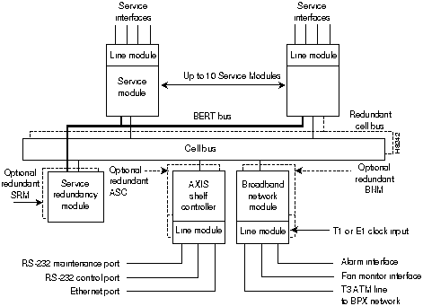
A simplified block diagram of the AXIS hardware is shown in Figure 2-2. As shown by the dashed lines, the ASC, SRM and Cellbus are all 1 for 1 redundant with one ASC, BNM, SRM slot set attached to one Cellbus, and the remaining ASC, BNM and SRM slot set tied to the other Cellbus.
Figure 2-2 : AXIS Top Level Block Diagram
Traffic management is provided by the AXIS Connection Congestion Management (ACCM) feature. This feature is a virtual source/virtual destination rate based closed loop feedback scheme between nodes based upon StrataCom's ForeSight and the ATM Forum Available Rate specification.Periodically the round trip delay (RTD) of a cell to the far end and back is calculated for each actual connection. The RTD is used to determine how frequently Foresight rate adjustment cells are sent to the far end. Based upon available bandwidth and current access rate, every few microseconds a Foresight cell is transmitted to the far end with any rate adjustments that may be necessary to make better use of the available bandwidth (rate is adjusted up, down or fast down). The AXIS MIB includes rate (MIR, PIR, and QIR) and adjustments (Up%, Down%, and Fast-Down%) objects.
ATM Local Management Interface (ATM LMI)
A Local Management Interface (ATM LMI) operates between the AXIS shelf and the BPX. The ATM LMI is used to communicate change of status of semi-permanent connections. The ATM LMI protocol conforms with that specified in ITU-TS Recommendation Q.2931, Sept. 1994. The ATM LMI also supports optional proprietary extensions to the ATM LMI for the reporting of node information and BNI queue configurations.
The two end points of the ATM LMI signaling are an ATM LMI process in the BCC in the BPX and an ATM LMI process in the ASC in the AXIS shelf. The ATM LMI PDUs are transported over an AAL5 connection (VPI=3/VCI=31) between the BNI on the BPX side and the BNM on the AXIS side. The ATM LMI process in the BPX can support ATM LMI connections for up to 16 AXIS shelves.
The StrataCom ATM LMI extension (which must be specifically enabled) uses a Node Update Status Message which is sent (BPX to AXIS or AXIS to BPX) whenever a change in Node Name, Node IP Address, Major Alarm Status, or Minor Alarm Status occurs. The message may optionally contain Qbin Status thereby allowing AXIS to configure the BNI port egress queues.
Auto Card Restore is a feature which allows a service module card to be removed and be hot plug replaced with another service module card keeping the same configuration. With this feature, the ASC maintains a copy of the configuration for each active service module.
The AXIS shelf is a 19" rack mountable unit conforming to the EIA RS-310-C standard and measuring:
The shelf contains a card cage with 16 slots, the slots are numbered 1 to 16 from the left looking at the front of the shelf.
A backplane runs across the card cage spanning all 16 slots. The backplane is positioned approximately 14" from the front of the cage allowing a function module card to be inserted in the slot from the front and a smaller line module card to be inserted in the slot from the rear.
Slots 1 and 2 are reserved for BNM cards (single or a redundant pair) and slots 3 and 4 are reserved for ASC cards (single or a redundant pair). Slots 15 and 16 are reserved for the SRM (single or redundant pair). Slots 1, 3, and 15 work together as an active or standby set, the same is true for slots 2, 4 and 16. Slots 5 through 14 (10 slots) are available for Service Modules (or IMATMs). For 1:N redundancy of T1/E1 service modules, standby cards must use slots 12, 13, and 14.
The shelf may house redundant power entry modules which are small cards installed horizontally in the bottom rear of the shelf. The AXIS shelf is powered by --48V DC power sources (single or redundant pair). Each power entry module is equipped with a circuit breaker. The shelf also provides a power receptacle for a cable to the cooling assembly which is mounted in the rack below the AXIS shelf (or shelves).
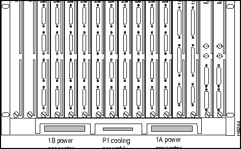
The backplane provides redundant system buses for communication between slots, power distribution to all slots and communication between front and back cards. Figure 2-3 and Figure 2-4 show the front and rear views of the AXIS shelf.
Figure 2-3 : Front view of the AXIS shelf with cards installed
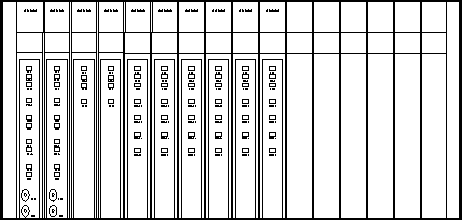
Figure 2-4 : Rear View of the AXIS Shelf
The AXIS backplane contains a main system bus, the cell bus, for communication between card slots. The cell bus consists of two pairs of unidirectional buses (for redundancy) which are used for transferring cells between the cell bus slave modules (FRSMs, AUSMs, ASCs) and the cellbus master (BNM).
The backplane also contains a local bus which permits the ASC to configure and monitor the BNM and SRM, a BERT bus for bit error rate testing, and a Redundancy bus for support of 1:N service module redundancy.
The backplane distributes --48VDC power to all card slots and all modules are hot insertable.
| Hardware | Weight (lbs) |
|---|---|
| AXIS shelf with 16 boards | 68 |
| AXIS main cooling unit | 20 |
| AXIS booster cooling unit | 14 |
| AXIS plenum | 8 |
| Average single AXIS board | 1.9 |
In DC powered systems AXIS supports one or two power entry modules (PEMs) each of which can be connected to its own independent 48V DC supply. The power entry modules are installed horizontally, side by side in the bottom rear of the shelf (see Figure 2-4). Each module is powered from a 48 V DC power source via three wires: positive ground, --48 V DC, and safety ground. The 48 VDC cable is connected to the power entry module through a 3- position EURO Block connector. The two modules provide power supply redundancy, each power entry module is capable of supplying enough power for a fully loaded AXIS shelf.
An illustration of a power entry module is shown in Figure 2-5
Figure 2-5 : AXIS Power Entry Module
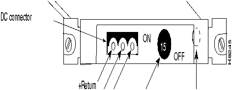
Each power entry module contains its own circuit breaker which also acts as an ON/OFF switch. The circuit breaker is closed by pressing in the large black button until it latches in the closed position. The circuit breaker is opened by pressing the smaller red button. The DC PEM also includes a bracket which is attached to the PEM to provide cable strain relief, see Chapter 6, "Installation and Start-up" for details.
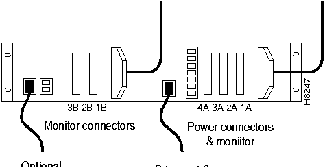
In AC powered systems, a separate AC power assembly is required, see Figure 2-6 and Figure 2-7. This assembly is rack mounted under the shelf cooling assembly in the rack and is available in both a single and double AC source line version. The power assembly has a modular design and can be configured with up to 6 power supply modules, each module providing 875 watts of 48 VDC power. The power assembly can provide power for up to 4 AXIS shelves, requiring 3 power supply modules, or 4 for a (1 for N) redundant power supply configuration. The rear panel has 4 connectors which supply 48 VDC power to the shelves. The first three (1A, 2A and 3A) connectors also provide power monitoring information to the AXIS shelf. Another 3 connectors (1B, 2B, and 3B) on the rear panel provide monitoring information for the second half of the power supply. Special cables are used from the rear of the power assembly to the rear of the shelves to feed power and monitor data to the shelves.
The AC power assembly measures:
Figure 2-6 : AC Power Assembly (front w/o grill)

Figure 2-7 : AC Power Assembly (rear)
DC Power Drain and Circuit Protection
Each card in an AXIS shelf draws an average of 21 Watts with a worst case shelf current of 14.40 amps.
The circuit breaker in the DC Power Entry Module (PEM) is rated at 15.00 amps.
The AXIS circuits are protected as follows:
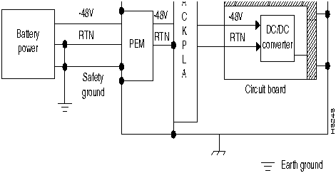
Each AXIS board is equipped with a DC/DC converter (Shindengen - HGG05006 or AT&T - JW030A) which has automatic current limiting to 5 volts output.
A schematic of the DC power system is shown in Figure 2-8
The AXIS cooling assembly consists of multiple rack-mounted units: a main cooling assembly, a booster cooling assembly, a plenum exhaust chamber, and a spacer unit.
The main cooling assembly measures:
The main cooling assembly is capable of providing cooling for up to two AXIS shelves and is mounted in the rack below the shelf (or shelves). The cooling assembly consists of fans which draw air through a filter at the front and exhaust air upwards through the shelf. An illustration of the cooling assembly is shown in Figure 2-9.

The booster cooling assembly measures:
The booster cooling assembly is used in racks with more than two AXIS shelves and is mounted above the shelves cooled by the main cooling assembly and below the shelves to which the booster cooling is to be provided. The booster cooling assembly consists of fans which draw air from the shelves below and exhaust air upwards through the shelf or shelves above. Each booster supports an additional two AXIS shelves. A system of up to 6 AXIS shelves can be supported (using one main cooling unit and two booster cooling units).
For both cooling assemblies, power is supplied to the connector at the rear of the cooling assembly by a cable running from the connector in the middle bottom rear of the AXIS shelf.
The assemblies provide output signals to the shelf such that the performance of the cooling assemblies can be monitored by the BNM cards. The cable delivering DC power to the cooling assembly from the AXIS shelf also carries these signals to the BNM via the backplane. The signals are such that the model of cooling assembly can be identified and the speed of each fan can be monitored (each fan generates a fixed number of square-wave pulses per revolution allowing the speed of the fan to be determined).
The Plenum chamber measures:
The exhaust plenum chamber is used in normal UL compliant installations where the top of the unit must be enclosed.The plenum chamber is mounted in the rack immediately above the shelf (shelves). The chamber delivers air from the shelf below out to the rear of the rack. The plenum chamber is preferred.
The spacer unit measures:
If used, the spacer unit is mounted in the rack immediately above the shelf (shelves).
The plenum chamber and spacer units are alternative methods for exhausting the cooling air from the rack. Either method can be used but not both. The spacer does NOT support the attachment of a cable management kit.
A cabinet is available from StrataCom which can be used to install AXIS, INS, BPX, and IGX equipment. StrataCom systems preconfigured in a cabinet can be ordered from StrataCom.
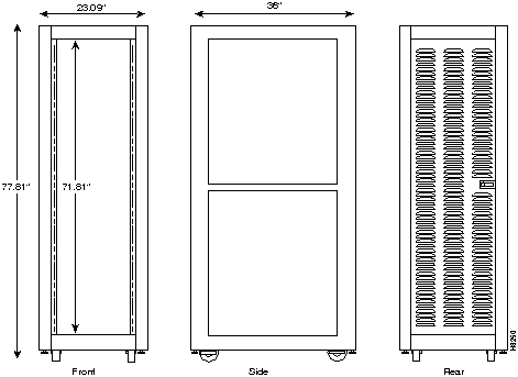
The cabinet, see Figure 2-10, is essentially a 19" rack with panels on all sides (including top and bottom) except the front. The rear panel is a louvered hinged door. The cabinet is equipped with casters, brakes and leveling bolts. The cabinet also includes earthquake safety holes so that the cabinet can be secured to the floor using studs.
The vertical height of the cabinet (including casters) is 80.31" providing 71.81" (41 rack mounting units) of vertical rack space.
The cabinet is 23" wide and 36" deep. Since AXIS modules are typically 22" deep, the cabinet provides approximately 12" of space behind the mounted AXIS modules for cables and cable management hardware.
Modules are installed in the cabinet in the same manner as installing in a 19" rack. Modules are installed by inserting them into the front of the cabinet and attaching them to the internal racks. All cables are connected through the rear door.
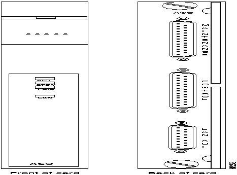
The AXIS Shelf Controller (ASC) is a two-card set consisting of an ASC front card and an ASC-BC back card. The shelf may contain a single ASC card set or a dual (redundant) card set. The cards are installed in slots 3 and/or 4. An illustration of the ASC card set is provided in Figure 2-11
The function of the ASC is to provide a user interface to provide overall control, configuration and management of the shelf. The ASC interfaces with the other cards in the shelf through the cell bus on the one side and with the user through console ports on the other side.
There are three ASC hardware console ports all located on the faceplate of the back card.
Some Ethernet transceivers with integrated DB-15 connectors cannot be connected directly to the LAN AIU Ethernet port on the AXIS ASC back card because of interference with the ASC back card extractor levers. To overcome this problem, two Ethernet Transceiver Extenders (one each for a primary and secondary ASC card) are provided.
If you encounter difficulty in connecting an Ethernet transceiver, install an extender on each ASC card as follows:
Note that additional access for shelf management is available through in-band communication over the ATM trunk.
See Appendix B for a summary of cable pin-outs
The ASC has the following LED indicators, all located on the faceplate of the front card.
ACTIVE (ACT) LED Green:
STANDBY (STBY) LED Yellow:
FAIL (FAIL) LED Red:
LAN (LAN) LED Green:
An illustration of the BNM card set is provided in Figure 2-12
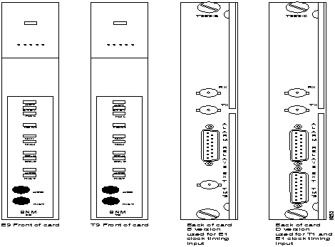
The Broadband Network Module (BNM) is a two-card set consisting of a BNM-T3 or E3 front card and a T3E3-D-BC or T3E3-B-BC back card. Either back card can be used with either front card except that the BNC clock connector only works for E1 clock sources. The shelf may contain a single BNM card set or a dual (redundant) card set. The cards are installed in slots 1 and/or 2.
The major function of the BNM is to provide a T3 or E3 ATM interface to an BNI card in a BPX node. The BNM also provides a number of miscellaneous functions as follows:
The BNM card accepts and transmits ATM cells over a T3 or E3 line interfaces at 44.736 Mbps or 33.368 Mbps respectively, asynchronously using StrataCom's STI (StrataCom Trunk Interface) protocol.
Framing occurs on the card using C-bit parity. An 8Khz clock is extracted from the received signal and can be used to synchronize the entire AXIS system.
The physical T3 or E3 ATM interface to the BNM is achieved via the BNM backcard. This physical connection is made with BNC connectors. There also exists relays on the backcard. These relays provide the continuity or discontinuity between the internal circuitry and the external BNC connectors for the Transmit and Receive lines.
These relays are also used as a mechanical loopback for the T3 or E3 bit stream.
AXIS implements the ATM STI cell format by using slot/channel numbers in the VPI/VCI fields in the cell format used between the BNM and the BPX BNI port. The cell format is shown in Figure 2-13 and Figure 2-14. The format on the left is the general STI format, the format on the right is the AXIS implementation.
In this format, the virtual circuit is defined by:
The CC/FFCI/Supv. field is used for ForeSight bits and a Supervisory bit.
Figure 2-13 : Rel 3.0 AXIS ATM Trunk Cell Format
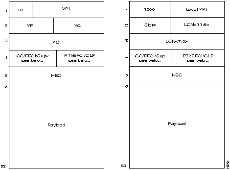
Figure 2-14 : CC, FFCI, EFCI, Supv, PTI, and CLP fields

The BNM has the following LED indicators, all located on the faceplate of the front card.
ACTIVE (ACT) LED Green:
STANDBY (STBY) LED Yellow:
FAIL (FAIL) LED Red:
PORT (PORT) LED Green, Red or Yellow:
MAJOR (MAJ) ALARM LED Red:
MINOR (MIN) ALARM LED Red:
DC OK A (DC-A) LED Green:
DC OK B (DC-B) LED Green:
ACO (ACO) LED Yellow:
HISTORY (HIST) LED Green:
The BNM has two push-buttons located on the faceplate of the front card.
Audible Cut-off (ACO) BUTTON:
History Clear (HIST) BUTTON:
An Illustration of the SRM-T1E1 card is provided in Figure 2-15
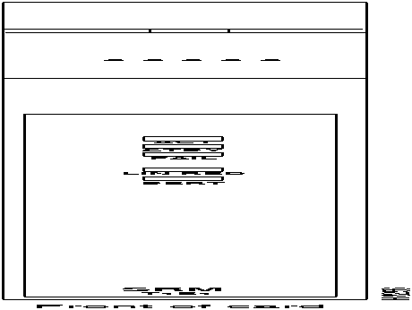
The Service Resource Module (SRM-T1E1) is a front card with no back card. The shelf may contain one SRM card in slot 15 or 16 or a dual (redundant) card set occupying slots 15 and 16. The SRM is hot insertable.
The SRM card serves two major functions for service modules. It provides for bit error rate testing (BERT) of T1 and E1 lines and ports and it provides 1for N redundancy (requires license).
The SRM has the following LED indicators, all located on the faceplate of the front card.
ACTIVE (ACT) LED Green:
STANDBY (STBY) LED Yellow:
FAIL (FAIL) LED Red:
LINE REDUNDANCY (LINE RED) LED Red:
BERT (BERT) LED Green:
|
|
Copyright 1988-1996 © Cisco Systems Inc.