|
|
This chapter provides the procedures for unpacking, installing and powering up the StrataCom AXIS shelf.
AXIS is designed for mounting in a standard 19" rack. The AXIS site, therefore, requires a 19" rack with sufficient available mounting units for the modules to be installed (5U for each shelf, 3U for the main cooling assembly, 2U for the booster cooling assembly, 2U for the plenum chamber or 1U for the spacer unit and 3U for the AC power module). The rack should have a set of mounting rails at the front and a second set either at the rear or in a designated intermediate position. There must be sufficient clearance around the rack to allow removal and replacement of front and back cards and for the attachment and routing of cables to the line modules. Ideally there should be at least 3 foot clearance in the front of the rack and 2 foot clearance in the back of the rack.
The AXIS shelf can be configured for either AC or DC power.
An easily accessible AC or DC power source must be available within 6 feet of the AXIS system. Before powering up the node, verify that the AXIS node is powered from a dedicated branch circuit. An easily accessible disconnect device should be included in the facility wiring.
A 20A DC circuit breaker is recommenced for the 48 VDC power source which supplies DC power to each AXIS shelf. This circuit breaker should protect against excess currents, short circuits, and earth faults in accordance with NEC, CEC, and ANSI/NFPA 70
For the DC version, a 48V DC power feed is required. For power supply redundancy, two such power feeds (preferably from independent power sources) are required. Each power feed must be capable of supplying 500 watts. The DC power connectors attach to the power entry modules at the rear of the shelf through EURO Block 3-pin connectors. For power and ground connections to AXIS, a 12 AWG conductors must be used. If the 48 VDC source has wires of a different gage, a customer supplied terminal block, that accepts the source wires as input and provides, as output, 12 AWG wires to the AXIS DC connector, must be provided. Only power supplies complying with SELV requirements in EN 60950 can be connected to the 48 VDC input of the AXIS system.
For the AC version a AC power source is required. For power supply redundancy, two such AC sources, (preferably independent) are required. Each source should be capable of supplying 500 watts per shelf. The AC power cables from the AC source attach to the AC power module which is mounted below the shelf and cooling assembly.
The site must be capable of maintaining a maximum ambient temperature of 50º C. while the system is operating (recommended range is 20° C to 30° C). A fully loaded AXIS shelf may dissipate up to 2400 BTUs.
The AXIS shelf, the Main Cooling Assembly, the Booster Cooling Assembly, the Plenum and Spacer, and the AC Power Module are each shipped in their own separate shipping containers.
To unpack and install the shelf and the cooling assembly, the following tools should be available:
Before proceeding with the installation, use the parts checklist to verify that all the parts you ordered are present and in good condition. If there are any missing or damaged parts, report the matter to your StrataCom Order Administration representative.
Plug-in cards may be shipped already installed in the shelf or under separate cover. The exact number of cards will vary from site to site, depending on the selected configuration. The AXIS shelf is shipped with all unused front and back slots covered with inserts which prevent radio frequency emissions and ensure proper air flow through the shelf. The unit must not be operated with any unused slots left uncovered.
The two 48V DC power feeds must be properly grounded on the positive 48 volt and safety ground pins.
Ensure that the AXIS frame and all other frames are attached to an isolated ground connection.
For AC systems, an insulated grounding conductor that is identical in size to the grounded and ungrounded branch circuit supply conductors, but is green with yellow stripes, is installed as part of the branch circuit that supplies the unit. The grounding conductor described is to be a separately derived system, at the supply transformer or motor generator set.
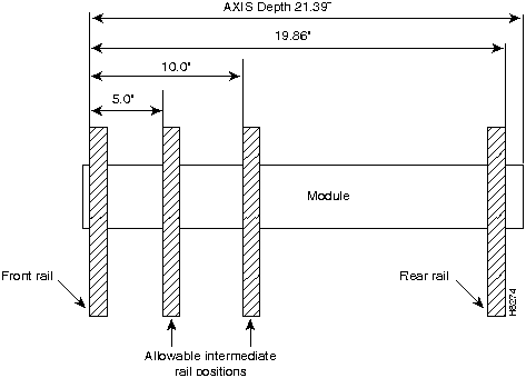
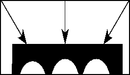
AXIS modules are designed to be mounted to two vertical rack mounting rails. A front mounting rail is used as one mounting point using the flanges provided at the front of each AXIS module. A second rail, either at the rear of the rack or at an intermediate position, is used for the second mounting point (mounting brackets are provided for attaching the module to the second rail). The allowable positions for intermediate rails is shown in Figure 6-1.
Figure 6-1 : Mounting Rail Positions The AXIS units are mounted in a specific order from the bottom to the top.
The AC power module (if used) is mounted first, then the fan cooling assembly is mounted, then the first shelf is mounted and, then the second shelf (if installed) is mounted fourth.
If a third and/or fourth shelf is installed, a booster cooling assembly must be mounted immediately above the second shelf and immediately below the third and fourth shelves. The plenum or spacer unit is mounted last above the highest shelf. If a cable management kit is to used in a 2 or 4 shelf rack, the top unit must be a Plenum because cable management hardware is not supported by the Spacer unit.
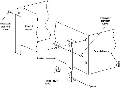
When each module is installed, there should be approximately 1/32 of an inch vertical space between adjacent modules. This can be achieved by ensuring that each module is installed at the center of each standard rack increment. This space is important because it allows cards, fan and power entry modules to be removed without interference. Hardware is available in the installation kits for this purpose (see Figure 6-5).
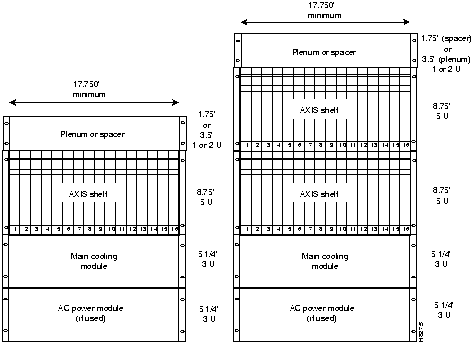
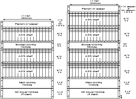
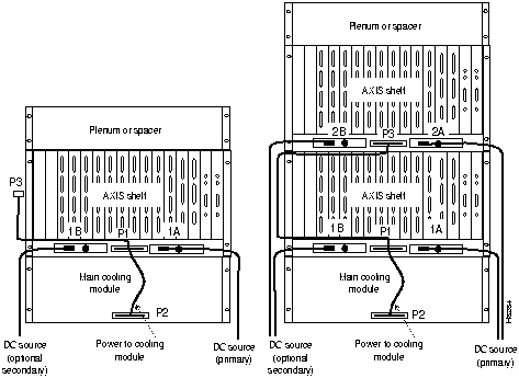
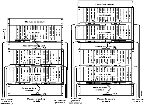
Racks with one and two shelves are shown in Figure 6-2. Racks with three and four shelves are shown in Figure 6-3
The AXIS shelf and Cooling Assembly rely on their contact with the rack for grounding. Therefore, the rack should be properly connected to earth.
The equipment should be mounted in the rack so as to prevent any hazardous condition due to uneven mechanical loading.
Figure 6-2 : Rack Mounted AXIS, One and Two Shelf Configurations Figure 6-3 : Rack Mounted AXIS, Three and Four Shelf Configurations Start by mounting the lowest module first and work upwards. In AC system, the lowest module is the AC power module, in DC systems it is the main cooling module.
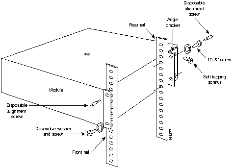
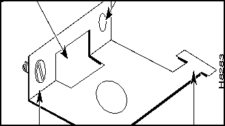
Figure 6-4 : Using Angle Bracket to secure Module to Rack Where there is restricted depth in the rack, the holes in the side of the module can also be used to mount the shelf such that the center of the module is mounted onto the front of the rack. In this arrangement, the shelf will protrude in the front of the rack and only partially protrudes into the rack space.
There are several aids for mounting modules where side access is limited.
Figure 6-5 : Keyhole Style Bracket Rack Mounting the Plenum or Spacer
Either the plenum chamber or the spacer unit (not both) should be mounted immediately above the shelf. The decision of which one to use is dependent upon the configuration of equipment in the rack and how the air is to be expelled. The plenum delivers air to the rear of the rack and is used in normal UL compliant installations where the top of the unit must be covered. The spacer may be used for installations that may have equipment mounted above the AXIS assembly that acts as the necessary top cover. The spacer guarantees the minimum necessary air exhaust space of 1.75 inches providing that the sides and rear are open and unobstructed. The AXIS shelf may not be UL compliant when the spacer is used. Further, the plenum supports the attachment of a cable management kit whereas the spacer does not. This is an important factor if cable management is to be used for the upper shelf in 2 and 4 shelf configurations.
Insert the selected unit immediately above the shelf and secure to the shelf with four #10-32 machine screws and flat washers.
Mounting the Electrostatic Wrist Strap
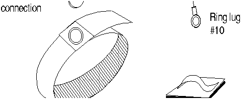
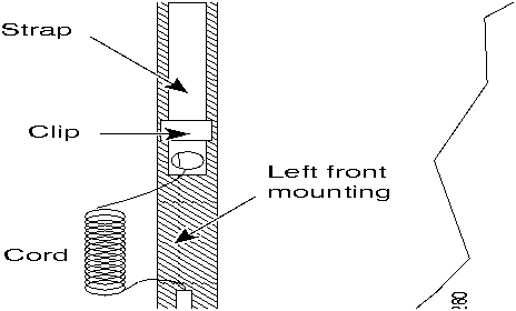
The AXIS shelf is provided with a wrist strap which grounds the user and protects the electronic components from electrostatic shock. The wrist strap kit consists of a strap, a coiled cord and a clip for holding the strap (see Figure 6-6).
It is recommended that the wrist strap is installed on the left front flange of one of the units at a convenient height. Use the a front mounting screw to secure the ring lug to the flange and front rail. The other end of the cord is attached to the strap with a snap connector. Peel the back off the clip to expose the adhesive surface and attach to the front of the unit above the ring lug, mount the clip sideways to allow the strap to be held in a position that will not interfere with the removal of the No. 1 card. Use the clip to store the strap when not in use.
Figure 6-6 : Electrostatic Wrist Strap Kit Figure 6-7 : Installed Wrist Strap Kit Colocating StrataCom Units in the Same Rack
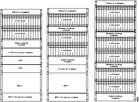
Different StrataCom units, for example, AXIS, BPX and FULCRUM can be collocated in the same rack or cabinet. When this is done however, the inclusion and positioning of AXIS power, cooling, booster, plenum, and spacer modules relative to the AXIS shelf must be the same as those when AXIS is used in a dedicated rack. Some example multi-system configurations are shown in Figure 6-8.
The configuration on the left includes a BPX, redundant FULCRUMs and two AXIS shelves. The center includes a BPX and three AXIS shelves. On the right is a 6 shelf DC arrangement.
In multi-system racks, the BPX, if included, should be mounted at the bottom. The AXIS shelves including the power, cooling, booster, plenum, and spacer should be mounted in the proper order at the top to allow for growth.
Figure 6-8 : Multi-system racks Connecting Power for DC Systems
Figure 6-9 : 48 VDC Male Power Receptacle when viewed while facing the Rear of the Shelf The DC cabling for single and multi-shelf racks is shown in Figure 6-11 and Figure 6-12.
DC Power to the Fan Cooling Assembly
A cable is provided with the main and booster cooling assemblies for delivering power from the shelf to the fan cooling assembly. The cable provides for redundancy and the Cooling unit can be powered from two independent shelves.
The cooling assembly cabling for a single and multi-shelf racks is also shown in Figure 6-11 and Figure 6-12.
Figure 6-11 : DC Power Cabling for One and Two Shelf Racks Figure 6-12 : DC Cabling for Three and Four Shelf Racks
Copyright 1988-1996 © Cisco Systems Inc.
![]()
![]()
![]()
![]()
![]()
![]()
![]()
![]()
![]()
![]()
![]()
![]()