|
|
This chapter explains the procedures for installing and starting the Cisco uBR7246. The chapter contains the following sections:
A rack-mount and cable-management kit is included in the shipping container. The rack-mount brackets in the kit are for mounting the Cisco uBR7246 in standard, 19-inch-wide, 4-post equipment racks or telco-type equipment racks. The rack-mount brackets are not suitable for use with other racks, such as 23-inch telco racks. The cable-management brackets are designed to relieve the strain on port adapter interface cables that are installed on port adapters in a Cisco uBR7246. If you are installing an equipment shelf or using mounting hardware other than that supplied with the chassis, review the guidelines in the section "Equipment Racks" in the chapter "Preparing for Installation," then proceed to the section "General Installation" in this chapter.
If you do not plan to install your Cisco uBR7246 in an equipment rack, proceed to the section "General Installation" later in this chapter.
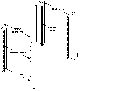
The chassis mounts to two rack posts with brackets that attach to either the front, middle, or rear sides of the chassis. The inside width between the posts or mounting strips (left and right) must be at least 17.00 inches (43.18 cm).
Some equipment racks provide a power strip along the length of one of the mounting strips. Figure 3-1 shows a typical 4-post equipment rack with a power strip along one of the back posts. If your rack has this feature, consider the position of the strip when planning fastener points and ensure that you will be able to pull port adapters and other FRUs straight out of their respective slots.
The inlet and exhaust ports for cooling air are located on the right and left of the chassis, respectively, so multiple universal broadband routers can be stacked in a rack with little or no vertical clearance.
 | Warning To prevent damage to the chassis or personal injury, never attempt to lift or tilt the Cisco uBR7246 using the port adapter handles or the I/O controller handle; they are not designed to support the weight of the universal broadband router. Always have someone help you when installing the Cisco uBR7246. |
| Warning To prevent the rack from tipping when installing the universal broadband router in telco-type racks, ensure that the rack is bolted to the floor and, if necessary, anchored with appropriate fixtures. |
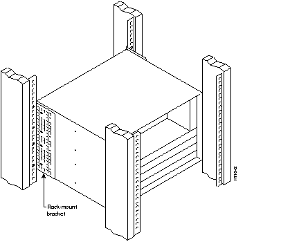
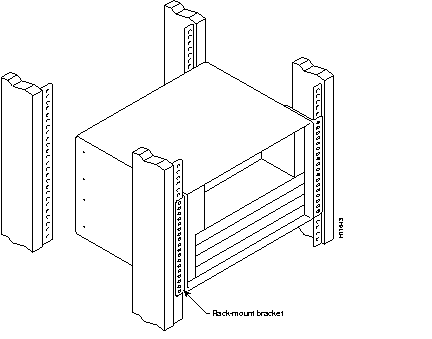
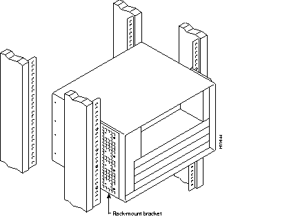
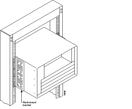
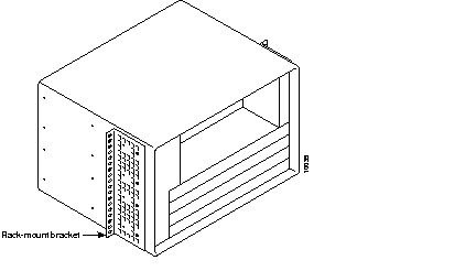
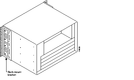
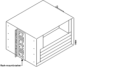
If you want to the port adapter and cable modem card end (the front) of the chassis recessed in the rack, install the rack-mount brackets at the rear of the chassis in the orientation shown in Figure 3-2. If you want the front of the chassis mounted flush with the front posts of the rack, install the rack-mount brackets at the front of the chassis in the orientation shown in Figure 3-3. If you want the front of the chassis protruding out of the rack, install the rack-mount brackets at the front of the chassis in the orientation shown in Figure 3-4. If you want the chassis in a telco-type rack, install the rack-mount brackets in the middle of the chassis in the orientation shown in Figure 3-5.
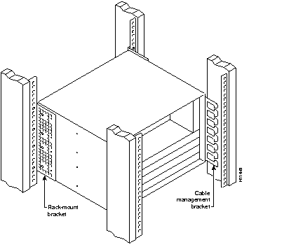
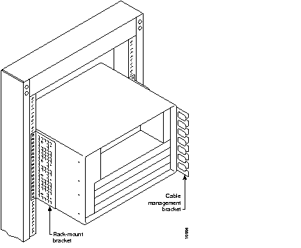
There are two cable-management bracket configurations available when rack-mounting the Cisco uBR7246. In the first configuration, for a 4-post rack, the rack-mount brackets are installed at the rear of the chassis and the cable-management bracket is installed at the right front of the chassis. You must install both sets of brackets before you install the chassis in the rack.
In the second configuration, for a telco-type rack, the rack-mount brackets are installed at the middle of the chassis and the cable-management bracket is installed at the right front of the chassis. You must install both sets of brackets before you install the chassis in the rack.
This section explains how to install the rack-mount brackets and cable-management bracket on a Cisco uBR7246 universal broadband router. Before installing the chassis in the rack, you must install a rack-mount bracket on each side of the front, middle, or rear of the chassis. If you are rack-mounting the chassis from the front, you cannot use the cable-management bracket.
If you are rack-mounting the chassis from the rear or middle of the chassis, you can install the rack-mount brackets and cable-management bracket separately; however, both rack-mount brackets and the single cable-management bracket must be installed on the chassis before the chassis is installed in the rack.
The parts and tools required for installing the rack-mount and cable-management brackets are listed in the section "Tools for Installation" in the chapter "Preparing for Installation" of this guide.
| Warning After attaching the brackets, and to avoid injury, we recommend that two people install the chassis in the rack. (One person should support the chassis in the rack while the second person installs the fasteners.) |
To install the rack-mount brackets on the chassis for a front rack-mount configuration, complete the following steps:
Step 1 Locate the threaded holes in the front sides of the chassis.
Step 2 If you want the front of the chassis flush with the front of the rack, align the first rack-mount bracket to the threaded holes in the right side of the chassis as shown in Figure 3-8.
If you want the front of the chassis protruding from the rack, align the first rack-mount bracket to the threaded holes in the right side of the chassis as shown in Figure 3-9.
Step 3 Thread four M4 x 6-mm Phillips flathead screws through the bracket and into the side of the chassis. Use a number 2 Phillips screwdriver to tighten the screws.
Step 4 Repeat Step 1 through Step 3 for the other rack-mount bracket.
This completes the procedure for installing the rack-mount brackets on the chassis for a front rack-mount configuration. Proceed to the section "Installing the Chassis in the Rack."
| Warning To prevent injury, review the safety precautions in the chapter "Preparing for Installation," before installing the universal broadband router in a rack. |
To install the rack-mount brackets and cable-management bracket on the chassis for a rear rack-mount configuration, complete the following steps:
Step 1 Locate the threaded holes in the rear sides of the chassis.
Step 2 Align the first rack-mount bracket to the threaded holes in the right side of the chassis.
Align the rack-mount bracket to the chassis as shown in Figure 3-10.
Step 3 Thread four M4 x 6-mm Phillips flathead screws through the rack-mount bracket and into the side of the chassis. Use a number 2 Phillips screwdriver to tighten the screws.
Step 4 Repeat Step 1 through Step 3 for the other rack-mount bracket.
Step 5 If you plan to include the cable-management bracket in your rear rack-mount configuration, align the bracket with the four right front side holes.
Step 6 Thread four M4 x 6-mm Phillips panhead screws through the cable-management bracket and into the chassis, and tighten the screws.
This completes the procedure for installing the rack-mount brackets and the cable-management bracket on the chassis for a rear rack-mount configuration. Proceed to the section "Installing the Chassis in the Rack."
To install the rack-mount brackets and cable-management bracket at the middle of the chassis for a telco-type rack-mount configuration, complete the following steps:
Step 1 Locate the threaded holes in the middle sides of the chassis.
Step 2 Align the first rack-mount bracket to the threaded holes in the right side of the chassis.
Align the rack-mount bracket to the chassis as shown in Figure 3-11.
Step 3 Thread four M4 x 6-mm Phillips flathead screws through the rack-mount bracket and into the side of the chassis. Use a number 2 Phillips screwdriver to tighten the screws.
Step 4 Repeat Step 1 through Step 3 for the other rack-mount bracket.
Step 5 If you plan to include the cable-management bracket in your telco-type rack-mount configuration, align the bracket with the four right front side holes.
Step 6 Thread four M4 x 6-mm Phillips panhead screws through the cable-management bracket and into the chassis, and tighten the screws.
This completes the procedure for installing the rack-mount brackets and cable-management bracket on the Cisco uBR7246. Proceed to the following section "Installing the Chassis in the Rack."
| Warning To prevent injury, review the safety precautions in the chapter "Preparing for Installation," before installing the universal broadband router in a rack. |
After installing the brackets on the chassis, mount the universal broadband router by securing the rack-mount brackets to four posts or mounting strips in the rack using the four slotted screws provided. Because the brackets support the weight of the entire chassis, be sure to use all four slotted screws to fasten the two rack-mount brackets to the rack posts. Figure 3-2, Figure 3-3, Figure 3-4, and Figure 3-5 show typical installations in 19-inch
4-post and telco-type equipment racks.
We recommend that you allow at least two inches of vertical clearance between the universal broadband router and any equipment directly above and below it.
| Warning To maintain a low center of gravity, ensure that heavier equipment is installed near the bottom of the rack. |
| Warning To prevent the rack from tipping when installing the universal broadband router in telco-type racks, ensure that the rack is bolted to the floor and, if necessary, anchored with appropriate fixtures. |
To install the chassis in the rack, complete the following steps:
Step 1 On the chassis, ensure that all captive screws on the network processing engine, the I/O controller, each cable modem card, and each power supply are tightened and the port adapter retention clip is in the locked position.
Step 2 Make sure that your path to the rack is unobstructed. If the rack is on wheels, ensure that the brakes are engaged or that the rack is otherwise stabilized.
| Warning To prevent damage to the chassis or personal injury, never attempt to lift or tilt the Cisco uBR7246 using the port adapter handles or the I/O controller handle; they are not designed to support the weight of the universal broadband router. Always have someone help you when installing the Cisco uBR7246. |
Step 3 Position the chassis so that the front end is closest to you; then lift the chassis and move it to the rack. To prevent injury, avoid sudden twists or moves.
Step 4 Slide the chassis into the rack, pushing it back until the brackets (installed at the front or rear of the chassis) meet the mounting strips or posts on both sides of the equipment rack.
Step 5 While keeping the brackets flush against the posts or mounting strips, position the Cisco uBR7246 so the holes in the brackets are aligned with those in the mounting strips.
Step 6 Insert all four 10-32 x 3/8 slotted screws (two on each side) through the brackets and into the mounting strip (use the top and bottom bracket holes, as shown in Figure 3-2, Figure 3-3, Figure 3-4, and Figure 3-5). Using a 7/16-inch, flat-blade screwdriver, tighten all the screws.
This completes the procedure for installing the chassis in the rack. Proceed to "Connecting Port Adapter Cables" in this chapter to continue the installation.
The Cisco uBR7246 should already be in the area where you will install it, and your installation location should already be determined. If not, refer to the section "Site Requirements" in the chapter "Preparing for Installation."
When installing the Cisco uBR7246 on a workbench or tabletop, ensure that the surface is clean and in a safe location and that you have considered the following:
Following are the steps for installing the Cisco uBR7246 on a workbench or tabletop:
Step 1 Remove any debris and dust from the tabletop or workbench, as well as the surrounding area. Also make sure your path between the Cisco uBR7246 and its new location is unobstructed.
Step 2 On the chassis, ensure that all captive screws on the network processing engine, the I/O controller, and each power supply are tightened and the port adapter retention clip is in the locked position
| Warning To prevent damage to the chassis or personal injury, never attempt to lift or tilt the Cisco uBR7246 using the port adapter handles or the I/O controller handle; they are not designed to support the weight of the universal broadband router. Always have someone help you when installing the Cisco uBR7246. |
Step 3 Lift the chassis by placing your hands around the chassis sides and lifting the chassis from underneath. To prevent injury, avoid sudden twists or moves.
Step 4 Place the Cisco uBR7246 on the tabletop or workbench.
Step 5 Ensure that there is at least three inches of clearance at the inlet and exhaust vents of the Cisco uBR7246 and no exhaust air from other equipment will be drawn into the chassis. Also, ensure that there is approximately 19 inches of clearance at the front and rear of the chassis.
This completes the general installation.
To install the cable-management bracket on the Cisco uBR7246, complete the following steps:
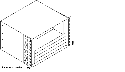
Step 1 Locate the threaded holes in the right front side of the chassis.
Step 2 Align the cable-management bracket with the four right front threaded holes in the chassis. (Refer to Figure 3-10.)
Step 3 Thread four M4 x 6-mm Phillips flathead screws through the bracket and into the chassis. Use a number 2 Phillips screwdriver to tighten the screws.
This completes the steps for installing the cable-management bracket on the Cisco uBR7246. Proceed to the following section, "Connecting Port Adapter Cables," to continue the installation.
Instructions for securing port adapter interface cables to the cable-management brackets are contained in the section "General Installation" in this chapter.
Instructions for securing cable modem card cables to the cable-management brackets are contained in the section "General Installation" in this chapter.
The console and auxiliary ports for the Cisco uBR7246 are located on the I/O controller. The I/O controller also has an optional Fast Ethernet port (refer to Figure 3-12.) This section contains connection equipment and pinout information for the console, auxiliary, and Fast Ethernet ports on the I/O controller.
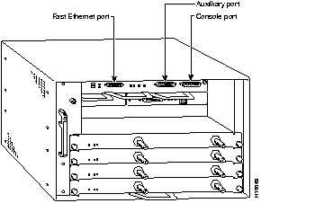
The I/O controller has two EIA/TIA-232 ports: a DCE-mode console port and a DTE-mode auxiliary port. The console port is a DCE DB-25 receptacle for connecting a data terminal, which you will use to configure the interfaces and bring up the Cisco uBR7246. The auxiliary port is a DTE DB-25 plug for connecting a modem or other DCE device (such as a CSU/DSU or other router) to the Cisco uBR7246 (refer to Figure 3-13).
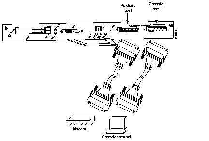
Before connecting a terminal to the console port, configure the terminal to match the Cisco uBR7246 console port as follows: 9600 baud, 8 data bits, no parity, 2 stop bits (9600 8N2). You need an EIA/TIA-232 DCE console cable to connect the terminal to the console port. After you establish normal universal broadband router operation, you can disconnect the terminal.
You must supply your own interface cable between the auxiliary port and the equipment you are connecting. For console and auxiliary port pinouts, refer to the following sections "Console Port Signals" and "Auxiliary Port Signals."
Both Data Set ready (DSR) and Data Carrier Detect (DCD) signals are active when the system is running. The Request To Send (RTS) signal tracks the state of the Clear to Send (CTS) input. The console port does not support modem control or hardware flow control. Table 3-1 lists the signals used on the console port. The console port requires a straight-through EIA/TIA-232 cable.
| Pin | Signal | Direction | Description |
|---|---|---|---|
| 1 | GND | - | Ground |
| 2 | TxD | <-- | Transmit Data |
| 3 | RxD | --> | Receive Data |
| 6 | DSR | --> | Data Set Ready (always on) |
| 7 | GND | - | Ground |
| 8 | DCD | --> | Data Carrier Detect (always on) |
Table 3-2 lists the signals used on the auxiliary port. The auxiliary port supports hardware flow control and modem control.
| Pin | Signal | Direction | Description |
|---|---|---|---|
| 2 | TxD | --> | Transmit Data |
| 3 | RxD | <-- | Receive Data |
| 4 | RTS | --> | Request To Send (used for hardware flow control) |
| 5 | CTS | <-- | Clear To Send (used for hardware flow control) |
| 6 | DSR | <-- | Data Set Ready |
| 7 | Signal Ground | - | Signal Ground |
| 8 | CD | <-- | Carrier Detect (used for modem control) |
| 20 | DTR | --> | Data Terminal Ready (used for modem control only) |
The Fast Ethernet port on the I/O controller has a single MII, 40-pin, D-shell type connector that is configurable for 100 megabits per second (Mbps). The MII connector supports IEEE 802.3u interfaces compliant with the 100BASE-X and 100BASE-T standards. The single MII connection requires an external transceiver that permits connection to multimode fiber for 100BASE-FX or 100BASE-T4 physical media (refer to Figure 3-14).
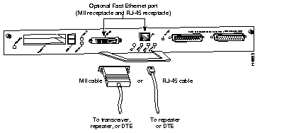
 | Caution Make sure input power to your Cisco uBR7246 is turned off and the universal broadband router is completely powered down before connecting an external transceiver to the Fast Ethernet port on the I/O controller. If you connect an external transceiver to the Fast Ethernet port when the Cisco uBR7246 is powered on, the system will reset and you could lose data. The I/O controller does not support OIR. |
Depending on the type of media you use between the MII connection and your switch or hub, the network side of your 100BASE-T transceiver should be appropriately equipped with ST-type connectors (for optical fiber), BNC connectors, and so forth.
Figure 3-15 shows the pin orientation of the female MII receptacle on the Fast Ethernet port.
The MII receptacle uses 2-56 screw-type locks, called jackscrews, to secure the cable or transceiver to the MII port. MII cables and transceivers have knurled thumbscrews that you fasten to the jackscrews on the MII connector and tighten with your fingers. Use the jackscrews to secure your MII cable to the MII receptacle.
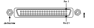
Table 3-3 lists the pinouts and signals for the I/O controller MII receptacle.
| Pin1 | In | Out | I/O | Description |
|---|---|---|---|---|
| 14-17 | - | Yes | - | Transmit Data (TxD) |
| 12 | Yes | - | - | Transmit Clock (Tx_CLK)1 |
| 11 | - | Yes | - | Transmit Error (Tx_ER) |
| 13 | - | Yes | - | Transmit Enable (Tx_EN) |
| 3 | - | Yes | - | MII Data Clock (MDC) |
| 4-7 | Yes | - | - | Receive Data (RxD) |
| 9 | Yes | - | - | Receive Clock (Rx_CLK |
| 10 | Yes | - | - | Receive Error (Rx_ER) |
| 8 | Yes | - | - | Receive Data Valid (Rx_DV) |
| 18 | Yes | - | - | Collision (COL) |
| 19 | Yes | - | - | Carrier Sense (CRS) |
| 2 | - | - | Yes | MII Data Input/Output (MDIO) |
| 22-39 | - | - | - | Common (ground) |
| 1, 20, 21, 40 | - | - | - | +5.0 volts (V) |
Following are the procedures for connecting AC-input power to your Cisco uBR7246.
Connect a 550W AC-input power supply as follows:
Step 1 At the rear of the Cisco uBR7246, check that the power switch on the power supply is in the OFF (0) position.
Step 2 Slide the cable-retention clip to the left, away from the AC receptacle, and plug in the power cable.
Step 3 Secure the cable in the power supply AC receptacle by sliding the cable-retention clip to the right until it fits around the connector. The cable-retention clip provides strain relief for the AC power cable (refer to Figure 3-16).
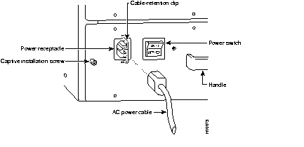
Step 4 Plug the AC power supply cable into the AC power source.
Step 5 Repeat Step 1 through Step 4 for the second power supply (if present).
This completes the procedure for connecting AC-input power.
Proceed to the following section "Starting the Cisco uBR7246" to start the universal broadband router.
After installing your Cisco uBR7246 and connecting cables, start the universal broadband router as follows:
Step 1 Check for the following:
Step 2 At the rear of the Cisco uBR7246, place the power switch on the power supply in the ON (|) position. Repeat this if a second power supply is installed. The green OK LED on the power supply turns on.
Step 3 Listen for the fans; you should immediately hear them operating. In a very noisy environment, also look for air movement around the chassis to verify that the fans are operating.
Step 4 During the boot process, observe the system LEDs. The LEDs on most of the port adapters go on and off in irregular sequence. Some may go on, go out, and go on again for a short time. On the I/O controller, the IO power OK LED comes on immediately.
Step 5 Observe the initialization process. When the system boot is complete (a few seconds), the network processing engine begins to initialize the port adapter, cable modem cards, and the I/O controller. During this initialization, the LEDs on each port adapter behave differently (most flash on and off). The enabled LED on each port adapter and cable modem card goes on when initialization is completed, and the console screen displays a script and system banner similar to the following:
Step 6 Configure the interfaces. When you start up the Cisco uBR7246 for the first time, the system automatically enters the setup command facility, which determines which port adapters are installed and prompts you for configuration information for each one. On the console terminal, after the system displays the system banner and hardware configuration, you will see the following System Configuration Dialog prompt:
--- System Configuration Dialog ---
At any point you may enter a questions mark '?' for help.
Default settings are in square brackets '[]'.
continue with configuration dialog? [yes]:
You have the option of proceeding with the setup command facility to configure the interfaces, or exiting from setup and using configuration commands to configure global (system-wide) and interface-specific parameters. You do not have to configured the interfaces immediately; however, you cannot enable the interfaces or connect them to any networks until you have configured them.
Many of the port adapter LEDs will not go on until you have configured the interfaces. To verify correct operation of each interface, complete the first-time startup procedures and configuration, then refer to the configuration note for each port adapter for LED descriptions and to check the status of the interfaces.
Your installation is complete. Proceed to the chapter "Performing a Basic Configuration of the Cisco uBR7246" to perform a basic configuration for your Cisco uBR7246.
|
|