|
|
This chapter provides information on the Catalyst 1200 series workgroup switch. The information is organized into the following sections:
The Catalyst 1200 series workgroup switch is a high-performance system that enhances network performance in client/server environments. The switch delivers Ethernet-to-Ethernet and Ethernet-to-CDDI/FDDI switching. It solves client/server networking problems with a seamless, high-bandwidth networking interface to servers and existing dedicated Ethernet desktop clients.
The Catalyst 1200 series workgroup switch supports the following basic configurations:
The switch's software enhancements provide additional management and control functions to the network manager. Virtual Networking Services (VNS) makes the Catalyst 1200 series workgroup switch the only switch that offers a comprehensive set of features to manage switched network traffic. VNS lets managers add, move, and change individual or multiple workgroups across a connected stack of switches. VNS also helps managers implement VLANs of multiple workgroups across switches and routers, provide for security controls to sensitive resources within these workgroups, and provide broadcast management services that optimize the performance of switched workgroups. The switched port analyzer, which is provided free of charge, lets a single network analyzer monitor all of the switch's switched Ethernet segments.
Optional enhanced monitoring services (EMS) make the Catalyst 1200 series switch the only switch that can comprehensively monitor switched workgroup traffic. The optional embedded RMON software lets the switch monitor traffic flow, identify the network's heavy users, and decode switched traffic for troubleshooting purposes.
Figure 133 : Catalyst 1200 Series Workgroup Switch Front Panel
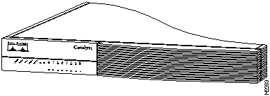
Figure 134 : Catalyst 1200 Series Workgroup Switch Rear Panel (10BaseT)
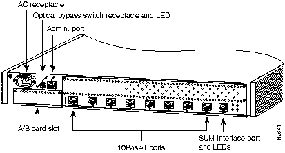
Figure 135 : Catalyst 1200 Series Workgroup Switch Rear Panel (10BaseFL)
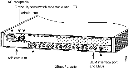
Table 270 : Catalyst 1200 Series Workgroup Switch Summary of Features
| Characteristics | Description |
|---|---|
| Placement | Desktop
19-inch rackmount hardware included Wall-mount hardware optional |
| Network management | Simple Network Management Protocol (SNMP) agent (RFC 11551157)
Station Management (SMT) Specification, Revision 7.3 Ethernet Management Information Base (MIB) RFC 1398 Spanningtree bridge MIB FDDI MIB (RFC 1285) MIB II (RFC 1213) Cisco-specific workgroup MIB Optional RMON agent (RFC 1271) |
| Maximum FDDI station-to-station cabling distance | 1.25 miles (2 km) using 62.5 or 50/125micron multimode fiber
18.6 miles (30 km) using single-mode fiber |
| Maximum CDDI station-to-station cabling distance | 330' (100 m) using Category 5 unshielded twisted-pair (UTP) or Type 1 shielded twisted-pair (STP) |
| Maximum Ethernet station-to-station cabling distance | 10BaseT: maximum segment length 330' (100 m)
10BaseFL: multimode fiber 1.25 miles (2 km) |
| Front panel indicators | Mechanical/electrical:
Switch status FDDI/CDDI: Ringop Thru Wrap A Wrap B 10BaseT/10BaseFL: Link status Transmit |
| Rear panel indicators | Optical bypass switch present LED
SUM port: Collision Link good Transmit Receive |
| Connectors | Ethernet:
8 Ethernet 10BaseT LAN ports (RJ-45) 8 Ethernet 10BaseFL LAN ports (ST multimode fiber) CDDI A/B port: RJ-45 FDDI A/B port: MIC multimode or ST single-mode |
| Administration interface | EIA/TIA-232 administration port (RJ-45) |
| Optical bypass switch | 6-pin mini-DIN |
| Processor | Motorola 68EC030 network management processor
IDT 3081 RISC data movement processor |
| Dimensions (H x W x D) | 2.7 x 18.0 x 16.0" (6.9 x 45.7 x 40.6 cm) |
| Weight (average shipping) | ~17 lb (~ 7.85 kg) |
| Agency approvals | UL 1950
CSA-C22.2 No. 950-M89 EN 60950 FCC Class A (47 CFR, Part 15) EN55022A VDE-B (fiber A/B) CE Mark VCCI-I |
Table 271 : Catalyst 1200 Series Workgroup Switch Environmental Specifications
| Description | Specification |
|---|---|
| Input | 100 to 240 VAC autoranging |
| Frequency | 50 to 60 Hz autoranging |
| AC current rating | 2.0A @ 110V; 1.0A @ 220V |
| Operating temperature range | 32 to 104°F (0 to 40°C) |
| Nonoperating temperature range | --40 to 167°F (--40 to 75°C) |

The Catalyst 1200 series workgroup switch includes the following standard features:

Catalyst 1200 series workgroup switch options include A/B port cards, software, and services such as SMARTnet agreements and documentation.
An A/B port card may be added to implement CDDI/FDDI A and B ports, as defined in the American National Standards Institute (ANSI) standard for dual attachment stations using the following media:
Figure 136 : A/B Port Cards
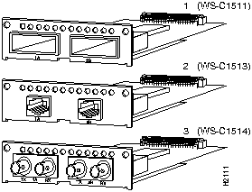
Cables must be ordered separately. See the section "Accessories," later in this chapter, for cable descriptions and ordering information.
Optional Software and Services
Catalyst 1200 series workgroup switch optional software and services include the following:
The following tables provide Catalyst 1200 series product numbers: see Table 272 for software and services and Table 273 for hardware product numbers.
Table 272 : Catalyst 1200 Series Workgroup Switch Software and Services
| Description | Product Number |
|---|---|
| CiscoView 3.0.3 for SunNet Manager---SunOS, Solaris | CV-3.0.3-SNM |
| CiscoView 3.0.3 for HP OpenView---SunOS, Solaris | CV-3.0.3-OVS |
| CiscoView 3.0.3 for HP OpenView---HP-UX | CV-3.0.3-OVH |
| CiscoView 3.0.3 for IBM NetView---NetView AIX | CV-3.0.3-NV |
| Catalyst EMS | WS-C12-EMS-LIC |
| Catalyst TrafficDirector for PC Windows | TRAFFDIR3.3-PC |
| Catalyst TrafficDirector for SunOS, Solaris | TRAFFDIR3.3-SUN |
| Catalyst TrafficDirector for HP-UX | TRAFFDIR3.3-HP |
| Catalyst TrafficDirector for IBM-AIX | TRAFFDIR3.3-IBM |
| SMARTnet agreement | CON-SNT-WS-C1200 |
| SMARTnet agreement for TrafficDirector (PC) | CON-SNT-TD-PC |
| SMARTnet for TrafficDirector (SunOS, Solaris) | CON-SNT-TD-SUN |
| SMARTnet for TrafficDirector (HP-UX) | CON-SNT-TD-HP |
| SMARTnet for TrafficDirector (IBM-AIX) | CON-SNT-TD-IBM |
| Additional documentation | See the chapter "Documentation" at the end of this catalog. |
Table 273 : Catalyst 1200 Series Workgroup Switch Hardware
| Description | Product Numbers |
|---|---|
| Catalyst 1200 series workgroup switch, 1,024 addresses, 8 10BaseT | WS-C1201 |
| Catalyst 1200 series workgroup switch, 4,096 addresses, 8 10BaseT | WS-C1202 |
| Catalyst 1200 series workgroup switch, 1,024 addresses, 8 10BaseFL | WS-C1211 |
| Catalyst 1200 series workgroup switch, 4,096 addresses, 8 10BaseFL | WS-C1212 |
| Catalyst 1200 series workgroup switch, 1,024 addresses, 8 10BaseT with bundled FDDI A/B (MIC) | WS-C1221 |
| Catalyst 1200 series workgroup switch, 1,024 addresses, 8 10BaseT with bundled CDDI A/B (MLT-3) | WS-C1241 |
| Catalyst 1200 series workgroup switch, 4,096 addresses, 8 10BaseFL with bundled FDDI A/B (MIC) | WS-C1251 |
| Catalyst 1200 series workgroup switch, 4,096 addresses, 8 10BaseFL with bundled CDDI A/B (MLT-3) | WS-C1261 |
| A/B port cards | |
| Multimode FDDI A/B port card, 100 Mbps | WS-C1511 |
| CDDI/MLT-3 A/B port card, 100 Mbps | WS-C1513 |
| Single-mode FDDI A/B port card, 100 Mbps | WS-C1514 |
This section describes the accessories available for the Catalyst 1200 switch. Each accessory is described, and the product number included, in Table 274.
Table 274 : Catalyst 1200 Series Workgroup Switch Accessories
| Description | Product Number |
|---|---|
| CDDI/FDDI media translator | WS-C703 |
| UTP cross-connect modular cable, 7' (2.12 m) | WS-C710 |
| UTP straight-through modular cable, 25' (7.57 m) | WS-C725 |
| STP-to-UTP converter | WS-C737 |
| FDDI patch cable, 7' (2.12 m), MIC-to-MIC | WS-C757 |
| FDDI patch cable, 7' (2.12 m), SC-to-MIC | WS-C767 |
| Cross-connect, 1' (.30 m), for A/B CDDI-port daisy chain | WS-C711 |
| 10-dB optical attenuator set | WS-C784 |
| Wall-mounting kit | WS-C1670 |
The C703 CDDI/FDDI media translator is used to convert between CDDI and FDDI links. It includes a transceiver and a +5V external 120-VAC power supply for North America. Table 275 provides specifications for the C703 CDDI/FDDI media translator.
Table 275 : CDDI/FDDI Media Translator Specifications
| Description | Specification |
|---|---|
| Connectors | 1 FDDI MIC
1 CDDI 8-pin RJ-45 |
| LEDs | FDDI signal detect
CDDI signal detect Power |
| Dimensions (H x W x D) | 1.5 x 3.5 x 5.6" |
| Translator power requirements | +5V |
| External power supply | 120 VAC, UL, CS |
| Agency compliance | FCC Part 15, Subpart J, Class A |
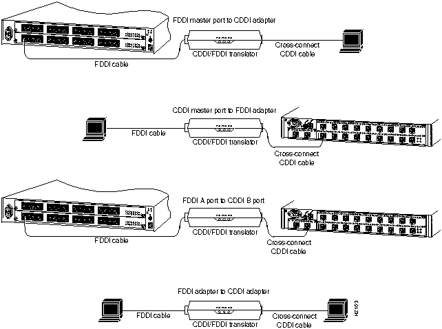
Figure 137 shows the most typical configurations for CDDI/FDDI translators. A standard patch cable is used to connect the FDDI side to the media translator. A cross-connect cable is used to connect the CDDI side, except when connecting a Workgroup 1000 concentrator (MLT-2), which requires a straight-through cable.
Figure 137 : Typical Configuration of the CDDI/FDDI Media Translator
Two kinds of unshielded twisted-pair (UTP) modular cables can be used---crossconnect and straightthrough:
The STP-to-UTP converter (WS-C737) is used to connect CDDI equipment to IBM Type 1 STP cabling systems.
The FDDI patch cable (WS-C757) is a seven-foot long, fiber-optic cable with MICs on each end.
The FDDI MIC-to-FDDI SC cable (WS-C767) is a seven-foot long, fiber-optic cable with a MIC on one end and an SC connector on the other end.
The optical attenuation set (WS-C784) includes two 10-dB optical attenuators, one for each signal direction. The set must be used in single-mode fiber applications having a total link attenuation of less than 10 dBs.
The wall-mounting kit (WS-C1670) contains hardware mounting accessories to mount the WS-C1200 chassis on the wall.
Workgroup products are shipped with North American power cords standard. Specify on your order alternate power cords for European (220V), U.K., Italian, or Australian power cords. For part numbers, see the chapter "Power Cords," later in this catalog.
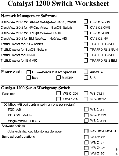
Use the following worksheet to help plan your order or to upgrade an existing system. One blank worksheet is provided, and you can make extra copies as needed.
________________________________________________________________________
|
|
Copyright 1988-1996 © Cisco Systems Inc.