|
|

Catalyst 5000 Series Group Switching Ethernet Module Configuration Note
Product Number: WS-X5020
This document contains instructions for installing the Catalyst 5000 Series Group Switching Ethernet Module (10BaseT 48 port). This document also contains procedures for configuring the module once it is installed. Configuration examples are also provided. For a complete description of commands used to configure and maintain the Catalyst 5000 series switch, refer to the Catalyst 5000 Series Configuration Guide and Command Reference publication. For complete hardware configuration and maintenance procedures, refer to the Catalyst 5000 Series Installation Guide publication. These documents are available on UniverCD or in printed form.
Sections in this document include the following:
![]()
What is the Catalyst 5000 Series Switch?
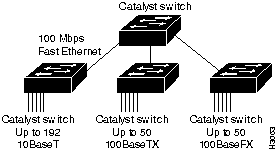
The Catalyst 5000 series switch provides high-density switched Ethernet for both wiring closet and data-center applications. The switch includes a single integrated 1.2 gigabit-per-second (Gbps) multiple-LAN-switching backplane, called the switching backplane, that supports switched 10-megabits-per-second (Mbps) and 100-Mbps Fast Ethernet with backbone connections to Fast Ethernet. Figure 1 is an example of a configuration using the Catalyst 5000 series switch.
Figure 1 : Cascaded Switches Using Fast Ethernet Interfaces on the Supervisor Engine Module
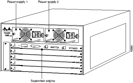
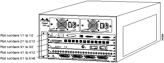
The Catalyst 5000 series switch chassis has five slots. The first slot is used for the supervisor engine module, which provides Layer 2 switching, local and remote management, and dual Fast Ethernet interfaces. The remaining four slots can be used for any combination of modules for additional 10- and 100-Mbps Ethernet. Figure 2 shows the rear view of the Catalyst 5000 series switch, which provides access to the supervisor engine and switching modules, power supply, and fan assembly. The LEDs on the supervisor engine module indicate normal system operation, switch load, and the currently active power supplies. The status LED turns green to indicate that the system is in a normal operating state.
Figure 2 : Catalyst 5000 Series Switch Chassis Rear View
Group Switching Ethernet Module (10BaseT 48 port) Description
The Group Switching Ethernet Module (10BaseT 48 port) provides a method to divide users into managed switch groups. Group switching combines hub costing and network management on one module; it is an alternative to shared-media hubs. Each module has four 10BaseT Ethernet segments with groups of 12 users per segment (48 interfaces per module).
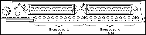
The Group Switching Ethernet Module, shown in Figure 3, provides connection to 48 10-Mbps (10BaseT) full- or half-duplex Ethernet interfaces using four RJ-21 Telco female ports (12 interfaces per port). You can switch each group of 12 ports to any Catalyst 5000 VLAN.
Figure 3 : Group Switching Ethernet Module (10BaseT 48 port)

Following are the Group Switching Ethernet Module (10BaseT 48 port) specifications:
Table 1 : Group Switching Ethernet Module (10BaseT 48 port) Specifications
| Description | Specification |
|---|---|
| Dimensions (H x W x D) | 1.2 x 14.4 x 16 inches (3 x 35.6 x 40.6 cm) |
| Weight | 5.7 lb (2.53 kg) |
| Environmental Conditions:
Operating temperature Nonoperating temperature Humidity |
32 to 104°F (0 to 40°C) -40 to 167°F (-40 to 75°C) 10 to 90%, noncondensing |
| Connectors | 4 RJ-21 IEEE 802.3 Ethernet 10BaseT |
| RAM buffer memory | 192 KB per group |
| Maximum station-to-station cabling distance | 10BaseT Ethernet: Category 3-5 UTP1: 328' (100 m)
100-Ohm STP: 328' (100m) |
| Frame processing | Transparent bridging (802.1d) |
| Network management | Ethernet MIB (RFC 1398)
Bridge MIB (RFC 1493) Ethernet Repeater MIB (RFC 1516) Interface Table (RFC 1573) RMON MIB (RFC 1757) Cisco Discovery Protocol Cisco VLAN Trunk Protocol (VTP) Cisco Workgroup MIB |
| Agency approvals
Safety: EMI2: |
UL3 1950, CSA4-C22.2 No. 950-93, and EN60950 FCC5 Class A (Part 15), EN 55022 Class B on shielded UTP, CE Mark, VCCI Class 2, CISPR 22 Class B on shielded UTP |
The five available interface slots on the Catalyst 5000 series switch support any combination of network interface switching modules, or any of the same type switching modules providing the maximum port densities up to 192 grouped switched Ethernet interfaces and two 100-Mbps switched interfaces.
Each switching module contains a status LED. When on, this LED indicates that the switching module is powered up. It does not necessarily mean that the interface ports are functional or enabled.
The LEDs on the faceplate of the Group Switching Ethernet Module (10BaseT 48 port) are described in Table 2 and shown in Figure 4.
Table 2 : Group Switching Ethernet Module (10BaseT 48 port) LED Descriptions
| LED | Description |
|---|---|
| Status | The switch performs a series of self-tests and diagnostic tests.
If the module is not receiving power, the status LED is off. If all the tests pass, the status LED is green. If a test other than an individual port test fails, the status LED is red. During system boot or if the module is disabled, the LED is orange. During self-test diagnostics, the LED is orange. If the module is disabled, the LED is orange. |
| LEDs
1 through 48 |
If the port is operational, the LED is green.
If the link has been disabled by software, the LED is orange. If the link is bad and has been disabled, the LED is flashing orange. If no signal is detected, the LED is off. |
Figure 4 : Group Switching Ethernet Module (10BaseT 48 port) LEDs
When preparing your site for network connections to the switch, you need to consider several factors related to each type of interface:
Before installing the switch, have all additional external equipment and cables on hand. If you intend to build your own cables, refer to the cable pinouts in the appendix "Cabling Specifications" in the Catalyst 5000 Series Installation Guide publication. For ordering information, contact a customer service representative.
The distance and rate limits discussed in this section are the IEEE recommended maximum speeds and distances for signaling; however, if you understand the electrical problems that might arise and can compensate for them, you should get good results with rates and distances greater than those described here. But, you do so at your own risk. The following distance limits are provided as guidelines for planning your network connections before installation.
The maximum distances for Ethernet network segments and connections depend on the type of transmission cable used, for example, unshielded twisted pair (10BaseT).
The IEEE recommends a maximum distance of 328 feet (100 meters) between station (connection) and hub for 10BaseT connections using Category 3 UTP.
You can use RJ-21 Telco male connectors to connect twelve 10-Mbps Ethernet to a punch-down block or patch panel. The Group Switching Ethernet module requires a 180 degree hood on the RJ-21 connector. Refer to Figure 5 for an example of an Ethernet RJ-25 Telco Interface 180o Cable connector.
Figure 5 : Ethernet RJ-25 Telco Interface 180o Cable Connectors
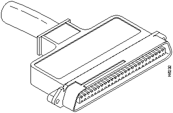
Table 3 lists the signals for the Group Switching Ethernet Module (10BaseT 48 port) RJ-21 Telco Ethernet connector.
Table 3 : Ethernet Switching Module RJ-21 Telco Ethernet Port Signals
| Pin
|
Signal
|
Direction
|
Description
|
Ethernet
Port No. |
|---|---|---|---|---|
| 1 | RxD -- | <--- | Receive Data | 1 |
| 2 | TxD -- | ---> | Transmit Data | 1 |
| 26 | RxD + | <--- | Receive Data | 1 |
| 27 | TxD + | ---> | Transmit Data | 1 |
| 3 | RxD -- | <--- | Receive Data | 2 |
| 4 | TxD -- | ---> | Transmit Data | 2 |
| 28 | RxD + | <--- | Receive Data | 2 |
| 29 | TxD + | ---> | Transmit Data | 2 |
| 5 | RxD -- | <--- | Receive Data | 3 |
| 6 | TxD -- | ---> | Transmit Data | 3 |
| 30 | RxD + | <--- | Receive Data | 3 |
| 31 | TxD + | ---> | Transmit Data | 3 |
| 7 | RxD -- | <--- | Receive Data | 4 |
| 8 | TxD -- | ---> | Transmit Data | 4 |
| 32 | RxD + | <--- | Receive Data | 4 |
| 33 | TxD + | ---> | Transmit Data | 4 |
| 9 | RxD -- | <--- | Receive Data | 5 |
| 10 | TxD -- | ---> | Transmit Data | 5 |
| 34 | RxD + | <--- | Receive Data | 5 |
| 35 | TxD + | ---> | Transmit Data | 5 |
| 11 | RxD -- | <--- | Receive Data | 6 |
| 12 | TxD -- | ---> | Transmit Data | 6 |
| 36 | RxD + | <--- | Receive Data | 6 |
| 37 | TxD + | ---> | Transmit Data | 6 |
| 13 | RxD -- | <--- | Receive Data | 7 |
| 14 | TxD -- | ---> | Transmit Data | 7 |
| 38 | RxD + | <--- | Receive Data | 7 |
| 39 | TxD + | ---> | Transmit Data | 7 |
| 15 | RxD -- | <--- | Receive Data | 8 |
| 16 | TxD -- | ---> | Transmit Data | 8 |
| 40 | RxD + | <--- | Receive Data | 8 |
| 41 | TxD + | ---> | Transmit Data | 8 |
| 17 | RxD -- | <--- | Receive Data | 9 |
| 18 | TxD -- | ---> | Transmit Data | 9 |
| 42 | RxD + | <--- | Receive Data | 9 |
| 43 | TxD + | ---> | Transmit Data | 9 |
| 19 | RxD -- | <--- | Receive Data | 10 |
| 20 | TxD -- | ---> | Transmit Data | 10 |
| 44 | RxD + | <--- | Receive Data | 10 |
| 45 | TxD + | ---> | Transmit Data | 10 |
| 21 | RxD -- | <--- | Receive Data | 11 |
| 22 | TxD -- | ---> | Transmit Data | 11 |
| 46 | RxD + | <--- | Receive Data | 11 |
| 47 | TxD + | ---> | Transmit Data | 11 |
| 23 | RxD -- | <--- | Receive Data | 12 |
| 24 | TxD -- | ---> | Transmit Data | 12 |
| 48 | RxD + | <--- | Receive Data | 12 |
| 49 | TxD + | ---> | Transmit Data | 12 |
| 25 | (Not Used) | |||
| 50 | (Not Used) |
The following guidelines will help to ensure your safety and protect the equipment. This list is not inclusive of all potentially hazardous situations that you may be exposed to as you install the switch, so be alert.
![]()
The supervisor engine, switching modules, and redundant (second) power supplies are designed to be removed and replaced while the system is operating without presenting an electrical hazard or damage to the system. Before removing a redundant power supply, ensure that the first supply is powered on. However, you must shut down the system before removing or replacing any of the replaceable components inside the front panel; for example, the backplane. Never install equipment that appears damaged.
Follow these basic guidelines when working with any electrical equipment:
In addition, use the guidelines that follow when working with any equipment that is disconnected from a power source but still connected to telephone wiring or other network cabling.
Preventing Electrostatic Discharge Damage
ESD damage, which occurs when electronic cards or components are improperly handled, can result in complete or intermittent failures. The supervisor engine module and switching modules each consist of a printed circuit card that is fixed in a metal carrier. Electromagnetic interference (EMI) shielding, connectors, and a handle are integral components of the carrier. Although the metal carrier helps to protect the cards from ESD, use a preventive antistatic strap whenever you handle the supervisor engine module or switching modules. Handle the carriers by the handles and the carrier edges only; never touch the cards or connector pins.
Following are guidelines for preventing ESD damage:
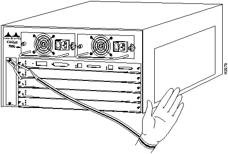
Figure 6 : Placement of ESD Wrist Strap
Installing and Configuring Switching Modules
All switching modules support hot-swapping, which allows you to install, remove, replace, and rearrange the switching modules without turning off the system power. When the system detects that a switching module has been installed or removed, it automatically runs diagnostic and discovery routines, acknowledges the presence or absence of the switching module, and resumes system operation without any operator intervention.
The hot-swapping feature allows you to remove and replace switching modules while the system is operating; you do not need to notify the software or shut down the system power. All switching modules support hot-swapping.
Each supervisor engine module and switching module contains a bus-type connector that mates with the system backplane. Each card connector consists of a set of tiered pins, in three lengths. The pins send specific signals to the system as they make contact with the backplane. When you remove or insert a switching module, the backplane, the system performs as follows:
When you insert a new switching module, the system runs a diagnostic test on the new interfaces and compares them to the existing configuration. If this initial diagnostic fails, the system remains off line for another 15 seconds while it performs a second set of diagnostic tests to determine whether or not the switching module is faulty and if normal system operation is possible.
If the second diagnostic test passes, which indicates that the system is operating normally and the new switching module is faulty, the system resumes normal operation but leaves the new interfaces disabled.
If the second diagnostic test fails, the system crashes, which usually indicates that the new switching module has created a problem in the bus and should be removed.
Incorrect Practices When Inserting and Removing Switching Modules
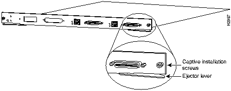
The function of the ejector levers (see Figure 7) on the supervisor and switching modules is to align and seat the card connectors in the backplane. Failure to use the ejector levers and insert the switching module properly can disrupt network activity. Follow the installation and removal instructions carefully, and review the following examples of incorrect insertion practices and results:
It is also important to use the ejector levers when removing a switching module to ensure that the card connector pins disconnect from the backplane in the logical sequence expected by the system. Any supervisor engine module or switching module that is only partially connected to the backplane can hang the bus. Detailed steps for correctly performing hot-swapping are included with the following procedures for installing and removing switching modules.
Figure 7 : Ejector Levers and Captive Installation Screws (Supervisor Engine Module Shown)
You need a 1/4-inch flat-blade screwdriver to remove any filler (blank) switching modules and to tighten the captive installation screws that secure the switching modules in their slots. Whenever you handle switching modules, you should use a wrist strap or other grounding device to prevent ESD damage. See the section "Preventing Electrostatic Discharge Damage."
Take the following steps to remove a switching module:
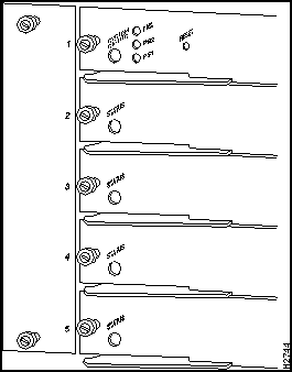
You can install switching modules in any of the four switching module slots, numbered 2 through 5 from top to bottom, when viewing the chassis from the rear. (See Figure 8.) The top slot contains the supervisor engine module, which is a required system component. Switching module fillers, which are blank switching module carriers, are installed in slots without switching modules to maintain consistent airflow through the switching module compartment.
Following is the procedure for installing a switching module.
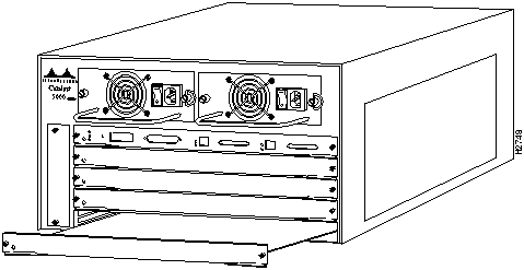
Figure 9 : Module Installation
Sample Screen Display for Hot-Swapping Procedure
When you remove and replace switching modules, the system provides status messages on the console screen. The messages are for information only. In the following sample display, using the show system and show module commands, you can follow the events logged by the system when an Ethernet switching module is removed from slot 2. If you then use the show ports command to query the module, the system responds, "Module 2 is not installed." When the Ethernet switching module is reinserted, the system marks the module as ready again.
After you install the switching module, use the following information to configure the module and the individual interfaces on the Ethernet switching port module. The section "Port Addresses" contains an overview of the port and module numbering scheme used to configure the Catalyst 5000 switching modules. The section "Configuring the Ethernet Ports" describes how to configure the ports on the Ethernet switching module. And the section "Checking the Configuration" describes the procedures you should use to confirm that the Ethernet switching module is configured correctly.
Each interface (or port) in the Catalyst 5000 series switch is designated by several different types of addresses. The physical interface address is the actual physical location (slot/port) of the interface connector within the chassis. The system software uses the physical addresses to control activity within the switch and to display status information. These physical slot/port addresses are not used by other devices in the network; they are specific to the individual switch and its internal components and software.
A second type of address is the MAC-layer or hardware address, which is a standardized data link layer address that is required for every port or device that connects to a network. Other devices in the network use these addresses to locate specific ports in the network and to create and update routing tables and data structures. The Catalyst 5000 series switch uses a unique method to assign and control the MAC-layer addresses of its interfaces.
The following sections describe how the Catalyst 5000 series switch assigns and controls both the physical (slot/port) and MAC-layer addresses for interfaces within the chassis.
In the Catalyst 5000 series switch, physical port addresses specify the actual physical location of each module port on the rear of the switch. (See Figure 10.) The address is composed of a two-part number in the format slot number/port number. The first number identifies the slot in which the switching module is installed. Module slots are numbered 1 to 5, from top to bottom. The second number identifies the physical port number on the switching module. The port numbers always begin at 1 and are numbered from the left port to the right port, when facing the rear of the switch. The number of additional ports (/1, /2, and so on) depends on the number of ports available on the module.
Interface ports maintain the same address regardless of whether other switching modules are installed or removed. However, when you move a switching module to a different slot, the first number in the address changes to reflect the new slot number. For example, on a 12-port 100BaseTX switching module in slot 2, the address of the left port is 2/1 and the address of the right port is 2/12. If you remove the 12-port 100Base TX switching module from slot 2 and install it in slot 4, the addresses of those same ports become 4/1 and 4/12.
Figure 10 : Interface Port Address Examples
Switching modules are always n/1, because each switching module supports at least one interface. (The multiple connectors on the switching modules are numbered /1 through /n, and so on.)
You can identify module ports by physically checking the slot/port location on the back of the switch. You can also use software commands to display information about a specific interface, or all interfaces, in the switch. To display information about every interface, use the show port command without parameters. To display information about a specific interface, use the show port command with the interface type and port address in the format show port [mod_num/port_num]. If you abbreviate the command (sho po) and do not include parameters, the system interprets the command as show port and displays the status of all interfaces.
Following is an example of how the show port command displays status information (including the physical slot and port address) for a Catalyst 5000 series switch. In this example, most of the status information is omitted.
For complete descriptions of the commands to configure and maintain the Catalyst 5000, refer to the Catalyst 5000 Series Configuration Guide and Command Reference.
All network interface connections (ports) require a unique MAC-layer address. Typically, the MAC address of an interface is stored on a component that resides directly on the interface circuitry. Every interface on the switch contains an electrically erasable programmable read-only memory (EEPROM) component with a unique MAC address for that interface. The switch system code reads the EEPROM for each interface in the system, learns the MAC addresses, and can then initialize appropriate hardware and data structures.
However, hot-swapping makes it necessary to use a different method of handling the MAC addresses in the Catalyst 5000 series switch. Hot-swapping allows you to remove a switching module and replace it with another identically configured switching module. If the new interfaces match the current configuration (of the interfaces you removed), the system immediately brings them online. In order to allow hot-swapping, an address allocator with numerous unique MAC addresses (four switching module slots times numerous possible ports on each) is stored in an EEPROM on the supervisor engine module. Each address is assigned to a specific slot/port in the switch regardless of whether or not an interface resides in that port. This address scheme allows you to remove switching modules and insert them into other switches without causing the MAC addresses to move around the network or be assigned to multiple devices.
Configuring the Ethernet Ports
This section describes how to use the administrative interface and the procedure used to configure the Ethernet ports on the Ethernet switching module.
To configure Ethernet ports, complete the tasks in the following sections:
Use the enable command to activate privileged mode. In privileged mode, certain commands are available, and certain displays have extra information.
The designation (enable) indicates that the system is in privileged mode and that privileged commands can be entered.
Example
The following example shows how to enter privileged mode:
Assign a name to each port. To set a port name, perform the following tasks in privileged mode:
Figure 11 : set port name Command Example
Figure 12 : Sample show port Command Display
Figure 13 : set port level Command Example
Enable the modules that will be used. To enable a module, perform the following tasks in privileged mode:
Figure 14 : set module enable Command Example
Figure 15 : Sample show module Command Display
Enable the ports that will be used. To enable a port, perform the following tasks in privileged mode:
Figure 16 : set port enable Command Example
VLANs allow ports on the same or different switches to be grouped so that traffic is confined to members of that group only. This feature restricts broadcast, unicast, and multicast traffic (flooding) to only ports included in a certain VLAN. You can set up VLANs for an entire management domain from a single Catalyst 5000 series switch.
Setting up VLANs for a management domain requires two tasks, as follows:
Create VLANs in a Management Domain The set vtp and set vlan commands use Virtual Trunk Protocol (VTP) to set up VLANs across an entire management domain. The default configuration has all switched Ethernet ports and Ethernet repeater ports grouped as VLAN 1.
By default, Catalyst 5000 switches have all of their interfaces in the no-management- domain state. They remain in this state until they are configured with a management domain or receive an advertisement for a domain. If a switch receives an advertisement, it inherits the management domain name and configuration revision number; it ignores advertisements with a different management domain or a smaller configuration revision number and checks all received advertisements with the same domain for consistency. While a Catalyst 5000 series switch is in the no-management domain state, it is a VTP client, that is, it learns from received advertisements but does not generate advertisements.
The set vtp command sets up the management domain. It establishes a management domain name, VLAN trunk protocol mode of operation (server or client), interval between VLAN advertisements, and password value. There is no default domain name (the value is set to null). The default advertisement interval is five minutes. The default VLAN trunk protocol mode of operation is set to server.
By default, VLANs are set to nonsecure mode, without a password. Adding a password sets the VLAN to secure mode. A password must be set at each Catalyst 5000 series switch in the management domain for each VLAN in secure mode.
The set vlan command uses the following parameters to create a VLAN in the management domain:
The Catalyst 5000 uses the security association identifier (SAID) parameter of the set vlan command to identify each VLAN. The default SAID for VLAN 1 is 1, for VLAN 2 is 2, for VLAN 3 is 3, and so on. The default maximum transmission unit (mtu) is 1,500 bytes. The default state is active.
When translating from one VLAN type (Ethernet, FDDI, Token Ring, FDDI NET, or TR NET) to another, the Catalyst 5000 series switch requires the VLAN number of the VLAN with a different type.
To create a VLAN across a networking domain, perform the following tasks in privileged mode:
Figure 17 : set vtp Command Example
Figure 18 : show vtp domain Command Example
Figure 19 : set vlan Command Example
Figure 20 : VLAN Configuration Across a Management Domain
Figure 21 : show vlan Command Display Sample
Grouping Switch Ports to VLANs A VLAN that is created in a management domain remains inactive until it is mapped to Catalyst 5000 switch ports. The set vlan command maps VLANs to ports.
The default configuration has all switched Ethernet ports. However, you can enter groups of ports as individual entries, for example, 2/1,3/3,3/4,3/5. You can also use a hyphenated format, for example, 2/1,3/3-5.
To create a VLAN, perform the following tasks in privileged mode:
Figure 22 : Example of the set vlan Command
Figure 23 : Local VLAN Configuration
Figure 24 : Sample show vlan Command Display
Set Up and Display the CAM Table
The following example shows how to add and display entries for the Content Addressable Memory (CAM) table. An entry for a single port affects an entire segment on the Group Switching Ethernet module. For details, refer to the Catalyst 5000 Series Configuration Guide and Command Reference publication.
Set Up Spanning-Tree Parameters
The following sections provide examples of spanning-tree commands, which are segment-based for the Group Switching Ethernet module:
Set Up the Port Cost The following example shows how to set up the spanning-tree port cost for the Catalyst 5000 Series Group Switching Ethernet module. Setting up the spanning tree port cost for a single port affects an entire segment.
Enable a Fast Start Connection The following example shows how to use the spantree portfast command to allow a port that is connected to a Group Switching Ethernet module and single workstation or PC to start faster. Enabling the spantree portfast command for a single port affects an entire segment.
Set the Spanning-Tree Port Priority The following example shows how to set up the spanning-tree port priority for the Group Switching Ethernet module. Changes made to the spanning-tree port priority of a single port affect an entire segment.
Display the Spanning Tree The following example shows how to display spanning-tree information for the Catalyst 5000, including information about the Group Switching Ethernet module.
Set Up Cisco Discovery Protocol (CDP)
Use the examples in the following sections to set up Cisco Discovery Protocol (CDP). These commands are segment-based for the Group Switching Ethernet module:
Enable CDP The following example shows how to enable the Cisco Discovery Protocol (CDP) for a segment of the Group Switching Ethernet module. Enabling CDP for a single port in a segment enables CDP for all the ports in the segment.
Set the CDP Interval The following example shows how to set the Cisco Discovery Protocol (CDP) interval for a segment of the Group Switching Ethernet module. The CDP interval for all ports of a segment are modified when you change the CDP interval for a single port in the segment.
Display CDP Information The following examples show how to display Cisco Discovery Protocol (CDP) port information using the show cdp command with a module number. All the ports for each segment of the Group Switching Ethernet module are displayed if you do not specify a port number.
Display Network Neighbors Using CDP The following example shows how to display the network neighbors of the Group Switching Ethernet module. Network neighbors for all the ports of each segment are displayed.
To access the information that certain MIB variables support, you must enter either an Interface Index (IF-INDEX) or Bridge Identifier (BridgeID) value as an instance identifier. The following sections describe how to access these types of values for use with specific MIBs:
Cisco-specific MIBs are available through ftp.cisco.com in the following locations:
Finding the Module Port Number from the Interface Extension MIB (RFC 1573) and Accessing the CDP MIB
To find the module number and port number to which an IF-INDEX is mapped, read the IfName in the MIB object of the Interface Extension MIB (RFC 1573). Use this method to find the IF-INDEX when you are accessing any of the variables in the CDP MIB that require an IF-INDEX for a variable instance identifier (such as "CDP neighbors").
The Catalyst 5000 Series Group Switching Ethernet module has 12 ports in each of its four switched, repeated segments. To gather statistical information about one of these segments using the Interface Extension MIB (RFC 1573) or CDP MIB, use the IF-INDEX of the first port of the segment (port 1, 13, 25 or 37) as the variable instance identifier.
Using RMON (RFC 1757) and SNMP MIBs with the Group Switching Ethernet Module
Standard remote monitoring (RMON, RFC 1757) supports nine types of monitoring groups. The Catalyst 5000 supports four of these groups: statistics, history, alarms, and events. Any RMON-compliant manager can obtain and display information from these groups. For example, the Cisco TrafficDirector application provides a simple, point-and-click method of obtaining the information. Refer to the TrafficDirector Windows User Guide or TrafficDirector UNIX User Guide for details about TrafficDirector.
Collecting remote monitoring (RMON) information requires you to create TrafficDirector software agents. These agents consist of a Catalyst 5000 IP address and an Interface Index (IF-INDEX) for the port about which information is to be collected. For instructions about how to display the IF-INDEX and the port number to which it is mapped, refer to the sections in this document "Displaying the IF-INDEX Using SunNet Manager" and "Displaying the IF-INDEX Using HP Openview." To gather statistical information using the Interface Extension MIB (RFC 1573) or CDP MIB, use the IF-INDEX of the first port of the segment (port 1, 13, 25 or 37) as the variable instance identifier.
Accessing the Bridge MIB (RFC 1493)
The Bridge MIB (RFC 1493) contains a bridge port number for each Catalyst 5000 Series Group Switching Ethernet module segment. Query the portCrossIndex.mod_num.port_num MIB object in the CISCO-STACK-MIB to find the BridgeID. The mod_num is the module number in the Catalyst 5000, and the port_num is the first port in each Group Switching Ethernet module segment (that is, port 1, 13, 25 or 37).
To display Bridge MIB information for different VLANs, change the SNMP community string to append @vlan_num to the configured SNMP community string. The vlan_num is the VLAN number.
Accessing the SNMP-REPEATER-MIB (RFC 1516)
To access the different segments of the Group Switching Ethernet module using the SNMP-REPEATER-MIB (RFC 1516), change the SNMP community string to add the following syntax:
The community_string represents the name of the SNMP community (the defaults are Public for Read-Only permission, private for Read-Write permission, and secret for Read-Write-All permission). The mod_num is the module number in the Catalyst 5000 and the port_num is the first port of each segment; for segment one use port 1, for segment two use port 13, for segment three use port 25, and for segment four use port 37.
Displaying the IF-INDEX Using SunNet Manager
To display the IF-INDEX and port number of a Catalyst 5000 using SunNet Manager, perform the following steps:
Displaying the IF-INDEX Using HP Openview
To display the IF-INDEX and port number of the Catalyst 5000 using HP Openview, perform the following steps:
This section describes procedures to confirm that your Ethernet (10BaseT 24 port) switching module is installed and configured correctly.
Use the ping command to send Internet Control Message Protocol (ICMP) echo request packets to another node on the network.
Syntax Description
Usage Guidelines
Following are sample results of the ping command:
Example
In the following example, host with IP alias elvis is pinged a single time, then pinged once per second until you enter Ctrl C to stop pinging:
Use the show mac command to show the cumulative statistics for a group of 12 ports on a per-segment basis. The following command examples illustrate the show mac command with the module number, both with and without the port number.
Use the show system command to display the power supply, fan, temperature alarm, system, and modem status; the number of days, hours, minutes, and seconds since the last system restart; the baud rate; the MAC address range; and the system name, location, and contact.
In the following example, the system status and other information are displayed:
Displaying the System Configuration
Use the show config command as follows to display the current system configuration:
Displaying the Port Configuration
Use the show port command as follows to display the current port configuration on a per-port basis:
Copyright 1988-1996 © Cisco Systems Inc.
![]()
![]()
![]()
![]()
![]()
![]()
![]()
![]()
![]()
Console> (enable) show system
PS1-Status PS2-Status Fan-Status Temp-Alarm Sys-Status Uptime d,h:m:s Logout
---------- ---------- ---------- ---------- ---------- -------------- ---------
ok         none       ok         off        ok         0,00:10:14     20 min

PS1-Type   PS2-Type   Modem   Baud  Traffic Peak Peak-Time
---------- ---------- ------- ----- ------- ---- -------------------------
WS-C5008   none       disable  9600   0%      0% Mon Apr 29 1996, 16:38:39

System Name              System Location          System Contact
------------------------ ------------------------ ------------------------

Console> (enable)
Console> show port
Console> (enable) show port
Port Name                 Status     Vlan       Level  Duplex Speed Type
---- -------------------- ---------- ---------- ------ ------ ----- -----------
1/1                       notconnect 1          normal   half   100 100BaseTX
1/2                       notconnect 1          normal   half   100 100BaseTX
2/1                       connected  1          normal   half    10 10BaseT
2/2                       notconnect 1          normal   half    10 10BaseT
.                                    .                              .
.                                    .                              .
.                                    .                              .
5/44                      notconnect 1          normal   half    10 10BaseT
5/45                      notconnect 1          normal   half    10 10BaseT
5/46                      notconnect 1          normal   half    10 10BaseT
5/47                      notconnect 1          normal   half    10 10BaseT
5/48                      notconnect 1          normal   half    10 10BaseT

Port Align-Err  FCS-Err    Xmit-Err   Rcv-Err
---- ---------- ---------- ---------- ----------
1/1           0          0          0          0
1/2           0          0          0          0
2/1           0          0          0          0
2/2           0          0          0          0
2/3           0          0          0          0
2/4           0          0          0          0
.                                   .
.                                   .
.                                   .
3/8           0          0          0          0
3/9           0          0          0          0
3/10          0          0          0          0
3/11          0          0          0          0
3/12          0          0          0          0

Port Single-Col Multi-Coll Late-Coll  Excess-Col Carri-Sens Runts     Giants
---- ---------- ---------- ---------- ---------- ---------- --------- ---------
1/1           0          0          0          0          0         0         -
1/2           0          0          0          0          0         0         -
2/1           0          0          0          0          0         0         0
2/2           0          0          0          0          0         0         0
.                                   .                               .
.                                   .                               .
.                                   .                               .
3/9           0          0          0          0          0         0         -
3/10          0          0          0          0          0         0         -
3/11          0          0          0          0          0         0         -
3/12          0          0          0          0          0         0         -

Port Auto-Parts Giants     Data-Rate  FCS-Err    Runts      Rcv-frms   Src-Addr
                           Mismatch                                    Changes
---- ---------- ---------- ---------- ---------- ---------- ---------- --------
5/1           0          0          0          0          0          0        0
5/2           0          0          0          0          0          0        0
5/3           0          0          0          0          0          0        0
5/4           0          0          0          0          0          0        0
.                                   .                                .
.                                   .                                .
.                                   .                                .
5/44          0          0          0          0          0          0        0
5/45          0          0          0          0          0          0        0

5/46          0          0          0          0          0          0        0
5/47          0          0          0          0          0          0        0
5/48          0          0          0          0          0          0        0

Port Rcv-Multi  Rcv-Broad  Good-Bytes Align-Err  Short-Evnt Late-Coll Collision
---- ---------- ---------- ---------- ---------- ---------- --------- ---------
5/1           0          0          0          0          0         0         0
5/2           0          0          0          0          0         0         0
5/3           0          0          0          0          0         0         0
5/4           0          0          0          0          0         0         0
.                                   .                               .
.                                   .                               .
.                                   .                               .
5/45          0          0          0          0          0         0         0
5/46          0          0          0          0          0         0         0
5/47          0          0          0          0          0         0         0
5/48          0          0          0          0          0         0         0

Last-Time-Cleared
--------------------------
Tue Apr 30 1996, 18:06:00
Console> (enable)
Console>
Console> enable
Enter password:
Console> (enable)
Task
Command
Configure a name for a port. Figure 11 shows an example of the set port name command.
set port name mod_num/port_num [name_string]
Verify that the port name is correct. Figure 12 shows a sample display of the show port command. Port names are listed in the Name column.
show port mod_num/port_num
Console> (enable) set port name 5/1 Router Connection
Port 5/1 name set.
Console> (enable) set port name 5/2 Server 1
Port 5/2 name set.
Console> (enable) show port 5/23
Port Name                 Status     Vlan       Level  Duplex Speed Type
---- -------------------- ---------- ---------- ------ ------ ----- -----------
5/23                      notconnect 1          normal   half    10 10BaseT

Port Auto-Parts Giants     Data-Rate  FCS-Err    Runts      Rcv-frms   Src-Addr
                           Mismatch                                    Changes
---- ---------- ---------- ---------- ---------- ---------- ---------- --------
5/23          0          0          0          0          0          0        0

Port Rcv-Multi  Rcv-Broad  Good-Bytes Align-Err  Short-Evnt Late-Coll Collision
---- ---------- ---------- ---------- ---------- ---------- --------- ---------
5/23          0          0          0          0          0         0         0

Last-Time-Cleared
--------------------------
Mon Apr 29 1996, 16:38:39

Console> (enable)
Task
Command
Configure the priority level for each port. Figure 13 shows an example of the set port level command.
set port level mod_num/port_num normal | high
Verify that the port priority level is correct. Figure 12 shows a sample display of the show port command, which shows the ports on a per-port basis. Port priority levels are listed in the Level column.
show port mod_num/port_num
Console> (enable) set port level 5/1 high
Port 5/1-12 level set to high.
Console> (enable) set port level 5/2 high
Port 5/1-12 level set to high.
Task
Command
Enter the module number of each module you want to enable. Figure 14 shows an example of the set module enable command.
set module enable mod_num
Verify that the module has been enabled. Figure 15 shows a sample display of the show module command. The Status column lists whether the module is enabled (ok) or disabled.
show module
Console> (enable) set module enable 1
Module 1 enabled.
Console> (enable) set module enable 5
Module 5 enabled.
Console> (enable) show module
Mod Module-Name          Ports Module-Type           Model   Serial-Num Status
--- -------------------- ----- --------------------- -------- --------- -------
1                        2     100BaseTX Supervisor  WS-X5009 002650292 ok
2                        24    10BaseT Ethernet      WS-X5010 000139910 ok
3                        12    100BaseF Ethernet     WS-X5111 002712121 ok
5                        48    4 Segment 10BaseT Eth WS-X5020 002532386 ok

Mod MAC-Address(es)                           Hw     Fw     Sw
--- ----------------------------------------  ------ ------ ----------------
1   00-40-0b-ff-00-00 thru 00-40-0b-ff-03-ff  1.81   1.5    2.132
2   00-40-0b-30-0a-38 thru 00-40-0b-30-0a-4f  0.405  1.4    2.132
3   00-40-0b-d5-02-f4 thru 00-40-0b-d5-02-ff  1.0    1.3    2.132
5   00-40-0b-14-00-6c thru 00-40-0b-14-00-6f  0.2    1.4369 2.132
Console> (enable)
Task
Command
Enter the module number of each module you want to enable. Figure 16 shows an example of the set port enable command.
set port enable mod_num/port_num
Verify that the port has been enabled. Figure 12 shows a sample display of the show port command. The Status column lists whether the module is enabled (indicated by the ready or connect status) or disabled.
show port mod_num/port_num
Console> (enable) set port enable 1/1
Port 1/1 enabled.
Console> (enable) set port enable 1/2
Port 1/2 enabled.
Console> (enable) set port enable 5/1
Port 5/1 enabled.
![]()
Task
Command
Define the VLAN management domain, indicating the domain name, VLAN trunk protocol mode of operation, interval between VLAN advertisements, and password value. Figure 17 shows an example of the set vtp command.
set vtp [domain name] [mode mode] [interval interval] [passwd passwd]
Verify that the VLAN management domain configuration is correct. Figure 18 shows a sample display of the show vtp domain command.
show vtp domain
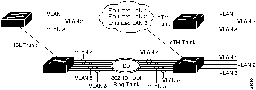
Define the VLAN, indicating the parameters described above: VLAN number, name, type, maximum transmission unit, SAID, state, ring number, bridge identification number, and number to indicate whether source routing should be set to transparent or bridging. Figure 19 shows an example of the set vlan command. Figure 20 shows a diagram of the established VLANs, illustrating how VTP can traverse trunk connections using the ISL and 802.10 protocols and ATM LAN emulation (LANE). In Figure 20, Ethernet VLAN 1 is translated to FDDI VLAN 4 on the FDDI module, Ethernet VLAN 2 is translated to FDDI VLAN 5, and so on.
set vlan vlan_num [name name] [type type] [mtu mtu] [said said] [state state] [ring ring_number] [bridge bridge_number] [parent vlan_num] [stp stp_type] [translation vlan_num]
Verify that the VLAN configuration is correct. Figure 21 shows a sample display of the show vlan command.
show vlan
Console (enable) set vtp
Usage:
set vtp [domain <name>][mode <mode>][interval <interval>]

  [passwd <passwd>]
(name: 1-32 characters, mode = (client, server, transparent),
  interval = 120-600 sec, passwd : 0-64 characters)
Console> (enable) set vtp domain engineering mode client interval 160
VTP: domain engineering modified
Console> (enable)
Console> show vtp domain
Domain Name                    Domain Index VTP Version Local Mode
------------------------------ ------------ ----------- -----------
engineering                    1            1           client

Last Updater    Vlan-count Max-vlan-storage Config Revision Notifications
--------------- ---------- ---------------- --------------- -------------
172.20.25.130   12         256              0               disabled
Console> (enable) set vlan
Usage:
set vlan <vlan_num> <mod/ports...>
set vlan <vlan_num> [name <name>][type <type>][mtu <mtu>][said <said>]
         [state <state>] [ring <ring_number>]
         [bridge <bridge_number>] [parent <vlan_num>]
         [stp <stp_type>] [translation <vlan_num>]
         (An example of mod/ports is 1/1,2/1-12,3/1-2,4/1-12
          type = (ethernet, fddi, token_ring, fddi_net, tr_net)
          name = 1..32 characters, status = (active, suspend)
          vlan_num = 1..1005)

Console> (enable) set vlan 3 name engineering type ethernet mtu 1500 said 3
VTP: vlan addition successful
Console> (enable)
Console> (enable) show vlan
VLAN Name                       Type  Status    Mod/Ports
---- -------------------------- ----- --------- ----------------
3    default                    enet  active    1/1-2
                                                2/1-24
                                                3/1-12
                                                5/1-48
1002 fddi-default               fddi  active
1003 token-ring-default         tring active
1004 fddinet-default            fdnet active
1005 trnet-default              trnet active


VLAN SAID       MTU   RingNo BridgeNo StpNo Parent Trans1 Trans2
---- ---------- ----- ------ -------- ----- ------ ------ ------
3    3          1500  0      0        0     0      0      0
1002 1002       1500  0      0        0     0      0      0
1003 1003       1500  0      0        0     0      0      0
1004 1004       1500  0      0        0     0      0      0
1005 1005       1500  0      0        0     0      0      0
Task
Command
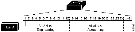
Define the VLAN and indicate the included ports. Figure 22 shows an example of the set vlan command. Figure 23 show a diagram of the established VLANs. In the example in Figure 22, VLAN 10, the engineering department, includes module 2, Ethernet ports 1 through 4. VLAN 20, the accounting department, includes module 2, Ethernet ports 5 through 24. The accounting and engineering departments are totally isolated from each other in this configuration.
set vlan vlan_num mod/ports
Verify that the VLAN configuration is correct. Figure 24 shows a sample display of the show vlan command.
show vlan
Console> (enable) set vlan 10 5/1-4
VLAN 10 modified.
VLAN 1 modified.
VLAN  Mod/Ports
---- -----------------------
10    5/1-12

Console> (enable) set vlan 20 5/13-16
VLAN 20 modified.
VLAN 1 modified.
VLAN  Mod/Ports
---- -----------------------
20    5/13-24
Console> (enable) show vlan
VLAN Name                       Type  Status    Mod/Ports
---- -------------------------- ----- --------- ----------------
1    default                    enet  active    1/1-2
                                                2/1-24
                                                3/1-12
                                                5/25-48
10   enet-default               enet  active    5/1-12
20   enet-default               enet  active    5/13-24
1002 fddi-default               fddi  active
1003 token-ring-default         tring active
1004 fddinet-default            fdnet active
1005 trnet-default              trnet active


VLAN SAID       MTU   RingNo BridgeNo StpNo Parent Trans1 Trans2
---- ---------- ----- ------ -------- ----- ------ ------ ------
1    1          1500  0      0        0     0      0      0
10   1          1500  0      0        0     0      0      0
20   1          1500  0      0        0     0      0      0
1002 1002       1500  0      0        0     0      0      0
1003 1003       1500  0      0        0     0      0      0
1004 1004       1500  0      0        0     0      0      0
1005 1005       1500  0      0        0     0      0      0
system1> (enable)
Console> (enable) set cam dynamic 2:3:4:5:6:7 5/47 1
Dynamic unicast entry added to CAM table.
Console> (enable) show cam dynamic
* = Static Entry. + = Permanent Entry. # = System Entry.

VLAN  Destination MAC      Destination Ports or VCs
----  ------------------   ----------------------------------------------------
1     00-40-0b-60-cd-98    2/1
1     00-40-0b-60-cd-96    2/1
1     00-40-0b-a0-04-32    2/1
1     00-40-0b-a0-04-29    2/1
1     00-40-0b-a0-02-b7    2/1
1     00-80-8c-01-02-6b    2/1
1     00-00-0c-35-7f-42    2/1
1     00-40-0b-4c-92-58    2/1
1     00-40-0b-ac-83-ff    2/1
1     00-40-0b-a0-6f-00    2/1
1     02-03-04-05-06-07    5/37-48
1     00-02-d0-05-40-ed    2/1
1     00-40-0b-80-50-24    2/1

Total Matching CAM Entries = 13

Console> (enable)
Console> (enable) set spantree portcost
Usage: set spantree portcost <mod_num/port_num> <cost>
       (cost = 1..65535)
Console> (enable) set spantree portcost 5/47 10
set spantree portcost 5/47 10
Spantree port 5/37-48 path cost set to 10.
Console> (enable) set spantree portfast 5/47 enable
set spantree portfast 5/47 enable

Warning: Spantree port fast start should only be enabled on ports connected
to a single host. Connecting hubs, concentrators, switches, bridges, etc. to
a fast start port can cause temporary spanning tree loops. Use with caution.

Spantree port 5/37-48 fast start enabled.
Console> (enable)
Console> (enable) set spantree portpri  5/47 62
Bridge port 5/37-48 port priority set to 62.
Console> (enable)
Console> (enable) show spantree
VLAN 1
Spanning tree enabled

Designated Root             00-40-0b-60-cd-96
Designated Root Priority    32768
Designated Root Cost        100
Designated Root Port        2/1
Root Max Age   20 sec    Hello Time 2  sec   Forward Delay 15 sec

Bridge ID MAC ADDR          00-40-0b-ff-00-00
Bridge ID Priority          32768
Bridge Max Age 20 sec    Hello Time 2  sec   Forward Delay 15 sec

Port      Vlan  Port-State     Cost   Priority  Fast-Start
--------  ----  -------------  -----  --------  ----------
1/1       1     not-connected     10        32   disabled
1/2       1     not-connected     10        32   disabled

2/1       1     forwarding       100        32   disabled
2/2       1     not-connected    100        32   disabled
.  .  .
.  .  .
.  .  .
3/10      1     not-connected    100        32   disabled
3/11      1     not-connected    100        32   disabled
3/12      1     not-connected    100        32   disabled
5/25-36   1     not-connected    100        32   disabled
5/37-48   1     not-connected     10        62   enabled
Console> (enable)
Console> (enable) set cdp enable 5/47
CDP enabled on port 5/37-48.
Console> (enable)
Console> (enable) set cdp interval 5/46 100
CDP message interval set to 100 seconds for port 5/37-48.
Console> (enable)
Console> (enable) show cdp port 5
Port     CDP Status  Message-Interval
-------  ----------  ----------------
5/1-12   enabled     60
5/13-24  enabled     60
5/25-36  enabled     60
5/37-48  enabled     100

Console> (enable) show cdp port 5/46
Port     CDP Status  Message-Interval
-------  ----------  ----------------
5/37-48  enabled     100
Console> (enable)
Console> (enable) show cdp neighbors 5
Port    Device-ID               Port-ID           Platform            Capability
------- ----------------------- ----------------- ------------------- ----------
5/1-12  000100808               1                 WS-C1201            S
5/1-12  002650014               2/1               WS-C5000            T
5/37-48 000041770               1                 WS-C1201            S
5/37-48 000100808               1                 WS-C1201            S
5/37-48 002650014               2/1               WS-C5000            T
5/37-48 atlas-gw.cisco.com      Ethernet0/2       cisco 7000          R
Console> (enable)
community_string@mod_num/port_num
/pub/mibs/schema/IF-MIB.schema
/pub/mibs/oid/IF-MIB.oid.
$SNMHOME/bin/snm -i
Apr 12 13:48:39 1996 [ 172.20.24.188 ] : Quick Dump: IF-MIB.ifXTable

KEY  ifName  ifInMulticastPkts  ifInBroadcastPkts...

1  sc0  0  0
2  sl0  0  0
3  1/1  0  0
4  1/2  0  0
5  2/1  0  0
6  2/2  0  0
7  2/3  0  0
8  2/4  0  0
9  2/5  0  0
10  2/6  0  0
11  2/7  0  0
12  2/8  0  0
13  2/9  0  0
14  2/10  0  0
15  2/11  0  0
16  2/12  0  0
/ftp/pub/mibs/V2/IF-MIB.my
/usr/OV/snmp_mibs
-s
Causes ping to send one datagram per second, printing one line of output for every response received. The ping command does not return any output when no response is received.
host
The IP address or IP alias of the host.
packet_size
(Optional) The number of bytes in a packet, from 1 to 2,000 bytes, with a default of 56 bytes. The actual packet size is eight bytes larger because the switch adds header information.
packet_count
(Optional) The number of packets to send
Ctrl-C
Stop pinging.
Console> ping elvis
elvis is alive
Console> ping -s elvis
ping elvis: 56 data bytes
64 bytes from elvis: icmp_seq=0. time=11 ms
64 bytes from elvis: icmp_seq=1. time=8 ms
64 bytes from elvis: icmp_seq=2. time=8 ms
64 bytes from elvis: icmp_seq=3. time=7 ms
64 bytes from elvis: icmp_seq=4. time=11 ms

64 bytes from elvis: icmp_seq=5. time=7 ms
64 bytes from elvis: icmp_seq=6. time=7 ms
^C

----elvis PING Statistics----
7 packets transmitted, 7 packets received, 0% packet loss
round-trip (ms)  min/avg/max = 7/8/11
Console>
Console> (enable) show mac 5
MAC       Rcv-Frms    Xmit-Frms   Rcv-Multi   Xmit-Multi  Rcv-Broad  Xmit-Broad
-------   ----------  ----------  ----------  ----------  ---------- ----------
5/1-12             0           0           0           0           0          0
5/13-24            0           0           0           0           0          0
5/25-36            0           0           0           0           0          0
5/37-48            0           0           0           0           0          0

MAC       Dely-Exced  MTU-Exced   In-Discard  Lrn-Discrd  In-Lost    Out-Lost
-------   ----------  ----------  ----------  ----------  ---------- ----------
5/1-12             0           0           0           0           0          0
5/13-24            0           0           0           0           0          0
5/25-36            0           0           0           0           0          0
5/37-48            0           0           0           0           0          0

MAC      Cols-count  Pkt-frag-ct Jabbers    Bytes-Trns
-------- ----------  ----------- ---------- ----------
5/1-12            0            0          0          0
5/13-24           0            0          0          0
5/25-36           0            0          0          0
5/37-48           0            0          0          0

Last-Time-Cleared
--------------------------
Mon Apr 29 1996, 16:38:39
Console> (enable) show mac 5/1
MAC       Rcv-Frms    Xmit-Frms   Rcv-Multi   Xmit-Multi  Rcv-Broad  Xmit-Broad
-------   ----------  ----------  ----------  ----------  ---------- ----------
5/1-12             0           0           0           0           0          0

MAC       Dely-Exced  MTU-Exced   In-Discard  Lrn-Discrd  In-Lost    Out-Lost
-------   ----------  ----------  ----------  ----------  ---------- ----------
5/1-12             0           0           0           0           0          0

MAC      Cols-count  Pkt-frag-ct Jabbers    Bytes-Trns
-------- ----------  ----------- ---------- ----------
5/1-12            0            0          0          0

Last-Time-Cleared
--------------------------
Mon Apr 29 1996, 16:38:39
Console> (enable)
Console> (enable) show system
PS1-Status PS2-Status Fan-Status Temp-Alarm Sys-Status Uptime d,h:m:s Logout
---------- ---------- ---------- ---------- ---------- -------------- ---------
ok         none       ok         off        ok         0,00:10:14     20 min

PS1-Type   PS2-Type   Modem   Baud  Traffic Peak Peak-Time
---------- ---------- ------- ----- ------- ---- -------------------------
WS-C5008   none       disable  9600   0%      0% Mon Apr 29 1996, 16:38:39

System Name              System Location          System Contact
------------------------ ------------------------ ------------------------

Console> (enable)
Console> show config
Console> (enable) show config
....................
begin
set password $1$FMFQ$HfZR5DUszVHIRhrz4h6V70
set enablepass $1$FMFQ$HfZR5DUszVHIRhrz4h6V70
set prompt Console>
set length 100 default
set logout 20
!
#system
set system baud  9600
set system modem disable
set system name
set system location
set system contact
!
#snmp
set snmp community read-only      public
set snmp community read-write     private
set snmp community read-write-all secret
set snmp rmon enable
set snmp trap disable module
set snmp trap disable chassis
set snmp trap disable bridge
set snmp trap disable repeater
set snmp trap disable vtp
set snmp trap disable auth
!
#ip
set interface sc0 1 172.20.25.127 255.255.0.0 172.20.255.255

set interface sl0 0.0.0.0 0.0.0.0
set arp agingtime 1200
set ip redirect   enable
set ip unreachable   disable
set ip fragmentation enable
set ip alias default         0.0.0.0
!

#Command alias
!
#bridge
set bridge ipx snaptoether   8023raw
set bridge ipx 8022toether   8023
set bridge ipx 8023rawtofddi snap
!
#vtp
!
#vlan
set vlan 1    2/1-24,5/1,5/13,5/25,5/37
!
#trunks
set trunk 1/1  auto 1-1000
set trunk 1/2  auto 1-1000
set trunk 3/1  auto 1-1000
set trunk 3/2  auto 1-1000
set trunk 3/3  auto 1-1000
set trunk 3/4  auto 1-1000
set trunk 3/5  auto 1-1000
set trunk 3/6  auto 1-1000
set trunk 3/7  auto 1-1000
set trunk 3/8  auto 1-1000
set trunk 3/9  auto 1-1000
set trunk 3/10 auto 1-1000
set trunk 3/11 auto 1-1000
set trunk 3/12 auto 1-1000
!
#cam
set cam agingtime 1    300
!
#cdp
set cdp enable   1/1-2,2/1-24,3/1-12,5/1,5/13,5/25,5/37
set cdp interval 1/1-2,2/1-24,3/1-12,5/1,5/13,5/25,5/37 60
!
#spantree
#vlan 1
set spantree enable         1
set spantree fwddelay 15    1
set spantree hello    2     1
set spantree maxage   20    1
set spantree priority 32768 1
set spantree portcost 2/1-24 100
set spantree portpri  2/1-24 32
set spantree portfast 2/1-24 disable
set spantree portcost 5/1,5/13,5/25,5/37 100
set spantree portpri  5/1,5/13,5/25,5/37 32
set spantree portfast 5/1,5/13,5/25,5/37 disable
!
#trunk
set spantree portcost     1/1  10
set spantree portpri      1/1  32
set spantree portvlanpri  1/1  0
set spantree portfast     1/1  disable
set spantree portcost     1/2  10
set spantree portpri      1/2  32
set spantree portvlanpri  1/2  0
set spantree portfast     1/2  disable
set spantree portcost     3/1  10
set spantree portpri      3/1  32
set spantree portvlanpri  3/1  0
set spantree portfast     3/1  disable
set spantree portcost     3/2  10
set spantree portpri      3/2  32
set spantree portvlanpri  3/2  0

set spantree portfast     3/2  disable
set spantree portcost     3/3  10
set spantree portpri      3/3  32
set spantree portvlanpri  3/3  0
set spantree portfast     3/3  disable
set spantree portcost     3/4  10
set spantree portpri      3/4  32
set spantree portvlanpri  3/4  0
set spantree portfast     3/4  disable
set spantree portcost     3/5  10
set spantree portpri      3/5  32
set spantree portvlanpri  3/5  0
set spantree portfast     3/5  disable
set spantree portcost     3/6  10
set spantree portpri      3/6  32
set spantree portvlanpri  3/6  0
set spantree portfast     3/6  disable
set spantree portcost     3/7  10
set spantree portpri      3/7  32
set spantree portvlanpri  3/7  0
set spantree portfast     3/7  disable
set spantree portcost     3/8  10
set spantree portpri      3/8  32
set spantree portvlanpri  3/8  0
set spantree portfast     3/8  disable
set spantree portcost     3/9  10
set spantree portpri      3/9  32
set spantree portvlanpri  3/9  0
set spantree portfast     3/9  disable
set spantree portcost     3/10 10
set spantree portpri      3/10 32
set spantree portvlanpri  3/10 0
set spantree portfast     3/10 disable
set spantree portcost     3/11 10
set spantree portpri      3/11 32
set spantree portvlanpri  3/11 0
set spantree portfast     3/11 disable
set spantree portcost     3/12 10
set spantree portpri      3/12 32
set spantree portvlanpri  3/12 0
set spantree portfast     3/12 disable
!
#module 1
set module name    1
set port enable    1/1-2
set port level     1/1-2  normal
set port duplex    1/1-2  half
set port trap      1/1-2  disable
set port name      1/1-2
!
#module 2
set module name    2
set module enable  2
set port enable    2/1-24
set port level     2/1-24  normal
set port duplex    2/1-24  half
set port trap      2/1-24  disable
set port name      2/1-24
!
#module 3
set module name    3
set module enable  3
set port enable    3/1-12
set port level     3/1-12  normal
set port duplex    3/1-12  half

set port trap      3/1-12  disable
set port name      3/1-12
!
#module 4 empty
!
#module 5
set module name    5
set module enable  5
set port enable    5/1-48
set port level     5/1,5/13,5/25,5/37  normal
set port trap      5/1-48  disable
set port name      5/1-48
!
#switch port analyzer
set span 1 1/1  both
set span disable
end
Console> (enable)
Console> (enable) show port 5
Port Name                 Status     Vlan       Level  Duplex Speed Type
---- -------------------- ---------- ---------- ------ ------ ----- -----------
5/1                       notconnect 1          normal   half    10 10BaseT
5/2                       notconnect 1          normal   half    10 10BaseT
5/3                       notconnect 1          normal   half    10 10BaseT
.                                    .                              .
.                                    .                              .
.                                    .                              .
5/45                      notconnect 1          other    half    10 10BaseT
5/46                      notconnect 1          other    half    10 10BaseT
5/47                      notconnect 1          other    half    10 10BaseT
5/48                      notconnect 1          other    half    10 10BaseT

Port Auto-Parts Giants     Data-Rate  FCS-Err    Runts      Rcv-frms   Src-Addr
                           Mismatch                                    Changes
---- ---------- ---------- ---------- ---------- ---------- ---------- --------
5/1           0          0          0          0          0          0        0
5/2           0          0          0          0          0          0        0
5/3           0          0          0          0          0          0        0
.                                   .                               .
.                                   .                               .
.                                   .                               .
5/45          0          0          0          0          0          0        0
5/46          0          0          0          0          0          0        0
5/47          0          0          0          0          0          0        0
5/48          0          0          0          0          0          0        0

Port Rcv-Multi  Rcv-Broad  Good-Bytes Align-Err  Short-Evnt Late-Coll Collision
---- ---------- ---------- ---------- ---------- ---------- --------- ---------
5/1           0          0          0          0          0         0         0
5/2           0          0          0          0          0         0         0
5/3           0          0          0          0          0         0         0
.                                   .                               .
.                                   .                               .
.                                   .                               .
5/45          0          0          0          0          0         0         0
5/46          0          0          0          0          0         0         0
5/47          0          0          0          0          0         0         0
5/48          0          0          0          0          0         0         0


Last-Time-Cleared
--------------------------
Mon Apr 29 1996, 16:38:39

Console>
![]()
![]()
![]()
![]()
![]()
![]()
![]()
![]()