|
|

LightStream 1010 ATM Switch Flash Memory Configuration Note
Product Numbers: MEM-ASP-16M=, MEM-ASP-32M=, MEM-ASP-64M=
This document contains instructions for installing and configuring the flash memory. For a complete description of commands used to configure and maintain the LightStream 1010 switch, refer to the LightStream 1010 ATM Switch Software Configuration Guide and the LightStream 1010 ATM Switch Command Reference publications. For complete hardware configuration and maintenance procedures, refer to the LightStream 1010 ATM Switch User Guide publication.
Cisco documentation and additional literature are available on a CD called Cisco Connection Documentation, Enterprise Series. The CD is updated and shipped monthly, so it might be more up-to-date than the printed documentation. To order the Cisco Connection Documentation, Enterprise Series CD, contact your local sales representative or call Customer Service. The CD is available both as a single CD and as an annual subscription. You can access Cisco technical documentation on the World Wide Web Universal Resources Locator (URL)
http://www.cisco.com.
Sections in this document include the following:
![]()
What is the LightStream 1010 ATM Switch?
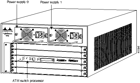
The LightStream 1010 uses a five-slot, modular chassis featuring the option of dual, fault-tolerant, load-sharing power supplies. (See Figure 1.) The central slot in the LightStream 1010 is dedicated to a single, field-replaceable ATM switch processor (ASP) module that supports both the 5-Gbps shared memory and the fully nonblocking switch fabric. The ASP also supports the feature card and high performance reduced instruction set (RISC) processor that provides the central intelligence for the device. The remaining slots support up to four hot-swappable Carrier Modules (CAMs). Each CAM supports up to two hot-swappable Port Adapter Modules (PAMs) for a maximum of eight PAMs per switch, supporting a wide variety of desktop, backbone, and wide-area interfaces.
Figure 1 : Front View of the LightStream 1010 ATM Switch
The LightStream 1010 ATM switch provides switched ATM connections to individual workstations, servers, LAN segments, or other ATM switches and routers using fiber-optic, unshielded twisted-pair (UTP), and coaxial cable.
The LightStream 1010 ATM switch can accommodate up to 32 OC-3, 8 OC-12, and 16 DS3 and E3 switched ATM ports in a standard 19-inch (48-centimeter) rack.
Figure 2 shows an example of a network configuration using the LightStream 1010 ATM switch in a high-performance workgroup.
Figure 2 : LightStream 1010 Workgroup Configuration Example
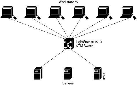
Figure 3 shows an example of a network configuration using the LightStream 1010 ATM switch for a campus backbone.
Figure 3 : LightStream 1010 Backbone Configuration Example
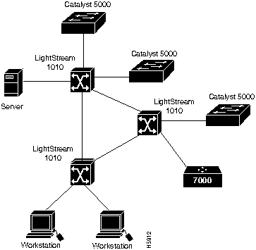
Table 1 lists the LightStream 1010 ATM switch specifications:
Table 1 : LightStream 1010 ATM Switch Specifications
| Description | Specifications |
|---|---|
| Switch and processor capacity | 5 Gbps1 shared memory, nonblocking switch fabric
65,536 cells of ATM cell buffers |
| Software images | Default image with IISP protocol
Optional PNNI image with plug-and-play capacity |
| Dimensions (H x W x D) | ASP: 1.2 x 14.4 x 16" (3.0 x 36.6 x 40.6 cm) |
| Microprocessor | 100-MHz MIPs R4600 |
| Memory | 8 MB of Flash memory (upgradeable to 16 MB)
16 MB of packet-buffer DRAM2 standard (upgradeable to 64 MB) 256 KB of boot EPROM 128 KB of SRAM3 |
| Interface timing | Loop timing, Stratum 4 accuracy clock for self-timing, master clock distribution port |
| ATM switch processor (ASP) | ASP module, 16 MB DRAM, 8-MB Flash memory, no Flash card installed (WATM-ASP1) |
| Management access | Standard Ethernet and dual EIA/TIA 232 serial ports on ASP module |
| ASP Interface ports | RJ-45 IEEE 802.3 Ethernet 10BaseT port
25-pin EIA/TIA-2324 AUX port and a DB-25 console port for an administration workstation |
| Mean Time Between Failures | 2.6 years for system configuration |
| Maximum
station-to-station cabling distance |
10BaseT Ethernet---Category 3-5 UTP5: 328 ft.(100 m)
ATM multimode---50/125-micron and 62.5/125-micron multimode fiber: 1.24 miles (2 km) ATM single-mode---8/125-micron single-mode fiber: 18.6 miles (30 km) |
| Agency approvals | Safety: UL6 1950, CSA7-C22.2 No. 950-93, and EN60950
EMI8: FCC Class A CE Mark, and VCCI Class II with shielded cables |
The eight available CAMs support any combination of network interfaces to provide the following maximum port densities:
You can install any combination of PAMs in any of the eight available PAM slots. There are no restrictions on either the number of modules that can be installed or their proximity to the ASP.
When preparing your site for network connections to the switch, you need to consider a number of factors related to each type of interface:
The following guidelines help ensure your safety and protect the equipment. This list is not inclusive of all potentially hazardous situations that you may be exposed to as you install the module, so be alert.
![]()
The supervisor engine, modules, and redundant (second) power supplies are designed to be removed and replaced while the system is operating without presenting an electrical hazard or damage to the system. Before removing a redundant power supply, make sure the first supply is powered on.
You must shut down the system before removing or replacing any of the replaceable components inside the front panel, for example, the backplane. Never install equipment that appears damaged.
Follow these basic guidelines when working with any electrical equipment:
In addition, use the following guidelines when working with any equipment that is disconnected from a power source but still connected to telephone wiring or other network cabling.
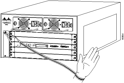
Preventing Electrostatic Discharge Damage
Electrostatic discharge (ESD) damage, which occurs when electronic cards or components are improperly handled, can result in complete or intermittent failures. The ASP and PAMs each consist of a printed circuit card that is fixed in a metal carrier. Electromagnetic interference (EMI) shielding, connectors, and a handle are integral components of the carrier. Although the metal carrier helps to protect the cards from ESD, use a preventive antistatic strap whenever you handle the ASP or PAMs. Handle the carriers by the handles and the carrier edges only; never touch the cards or connector pins.
Following are guidelines for preventing ESD damage:
Figure 4 : Placement of Electrostatic Discharge Wrist Strap Replacing SIMMs (Upgrading DRAM)
The system DRAM resides on a Single In-Line Memory Module (SIMM) on the ASP. The default DRAM configuration is 16 MB. This section provides the steps for increasing the amount of DRAM from 16 MB to 32 or 64 MB by adding two 16- or 32-MB SIMMs.
The amount of DRAM required on the ASP module is determined by the number of active physical and logical ports (virtual path tunnels) and the expected number of active switched virtual channels (SVCs) through the switch. Table 2 is an approximate guide that should be used when determining the amount of DRAM required for a switch with 32 physical ports.
Table 2 : DRAM Required Determined by SVCs
Although the SIMM specifications are defined in the manufacturers' part numbers, the SIMMs must meet the following requirements:
You need the following parts and tools to replace SIMMs. If you need additional equipment, contact a customer service representative for ordering information.
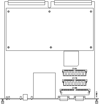
The system DRAM resides in two SIMMs on the ASP. The DRAM SIMM sockets are U164 and U178. The default DRAM configuration is 16 MB (two 8-MB SIMMs). (See Figure 5.)
Figure 5 : ATM Switch Processor SIMM Sockets Before proceeding, you must met the following prerequisites:
Place removed SIMMs on an antistatic mat and store them in an antistatic bag. You can use the SIMMs that you remove in compatible equipment. To prevent ESD damage, handle SIMMs by the card edges only.
Follow these steps to remove the existing SIMMs:
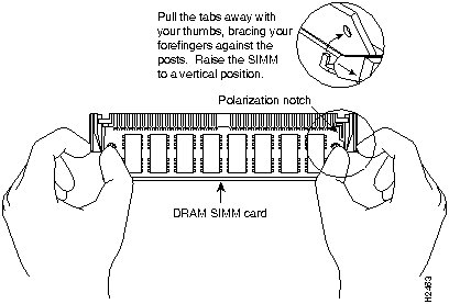
Figure 6 : Releasing the SIMM Spring Clips This completes the SIMM removal procedure. Proceed to the next section to install the new SIMMs.
SIMMs are sensitive components that are susceptible to ESD damage. Handle SIMMs by the edges only; avoid touching the memory modules, pins, or traces (the metal fingers along the connector edge of the SIMM). (See Figure 7.)
Follow these steps to install the new SIMMs:
The SIMM replacement procedure is now complete.
To replace the ASP in the chassis, see the section "Installing and Replacing the ASP, CAMs, and PAMs" in the LightStream 1010 ATM Switch User Guide. After the rasp is replaced, restart the system for an installation check.
If the system fails to boot properly, or if the console terminal displays a checksum or memory error, check the following:
If after several attempts the system fails to restart properly, contact a service representative for assistance. Before you call, make note of any error messages, unusual LED states, or any other indications that might help solve the problem.
Copyright 1988-1996 © Cisco Systems Inc.
![]()
![]()
![]()
DRAM Required
SVCs Required
16 MBytes DRAM
Less than 4000 active SVCs
32 MBytes DRAM
Between 4000 and 16000 active SVCs
64 MBytes DRAM
Between 16000 and 32000 active SVCs
![]()
![]()

![]()
![]()
![]()
![]()
![]()
![]()
![]()
![]()
![]()
![]()