
Table of Contents
Configuring VLANs and Links
Configuring VLANs and Links
After you have become familiar with the basics of VlanDirector, you are ready to configure VLANs and links. Use the information in this chapter whether you are configuring VLANs for the first time, or whether you have already configured some VLANs on your network using the CLI interface on your switches or using CiscoView.
This section describes how to perform the following tasks:
- Configuring VLANs
- Creating a new VLAN
- Naming VLANs
- Adding ports to a VLAN
- Creating bridged VLANs
- Modifying VLANs
- Moving ports among VLANs
- Searching for a VLAN component
- Merging VLANs
- Renaming VLANs
- Deleting VLANs and VLAN Components
- Deleting a port from a VLAN
- Deleting a VLAN or folder
- Deleting a switch from a VLAN
- Configuring Links
- Configuring links
- Adding a link to a VLAN
- Deleting a link from a VLAN
- Selecting links and load-balancing
- Load-sharing along parallel links
- Displaying the forwarding links in a Spanning Tree Protocol (STP) environment
- Selecting preferred links
- Saving changes
- Quitting VlanDirector
Creating a New VLAN
To create a new VLAN, create a VLAN name, and then add ports to the VLAN.
When you first start VlanDirector, the Names window shows the names of existing VLANs or folders. If you have assigned VLANs outside of VlanDirector (for example, using the CLI interface on the switch), the names of these VLANs are retained when you first launch VlanDirector and are displayed in the Names window.
In addition, the Names window includes the names of two default VLANs: an Ethernet Default VLAN called "default" and an FDDI default VLAN called "FDDI-default."
These VLANs are the default VLANs to which all ports are assigned when you first install your Cisco switches.
Figure 4-1 : Names Window Showing Default VLANs
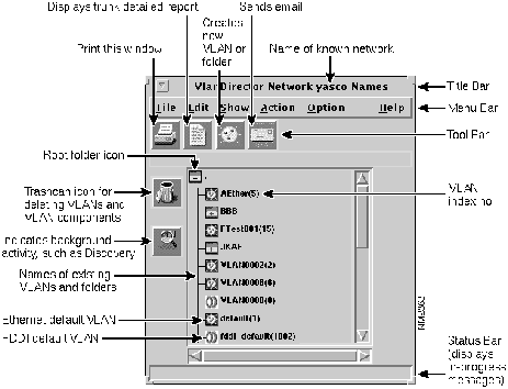
Figure 4-1 shows an example of the Names window with default VLANs.
When you add ports to a VLAN, you move ports from the default VLAN or other existing VLANs to the new VLAN.
VlanDirector is unable to determine which ports in the default VLAN are in use. Therefore, you should keep careful records of port usage.
Creating a New VLAN Name
To create a new VLAN name, follow these steps:
Step 1 In the Names window, select a folder icon. If you are creating a VLAN for the first time, only one folder icon exists. This folder is called the root folder and is located in the top left corner of the window pane, as shown in Figure 4-1. You can create a single VLAN name or create a folder to contain more than one VLAN name. This example shows how to create a single VLAN name.
Step 2 In the Names window, select Action>Create VLAN or Folder, or click the Create VLAN icon in the tool bar.
- The VlanDirector Create Names Entry window is displayed as follows:
Figure 4-2 : VlanDirector Create Names Entry Window
-
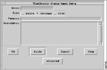
Step 3 In the Name field, specify the name of the new VLAN. For example, enter mktg to specify mktg as the name of the new VLAN. Folder names and VLAN names together cannot exceed 32 alphanumeric or symbolic characters.
- For a list of invalid characters in VLAN names or folders, see Naming VLANs later in this chapter. You can use both uppercase and lowercase characters, but no spaces.
Step 4 In the Type field, click the Ethernet or FDDI radio button to indicate the type of VLAN you are creating.
Step 5 You can, optionally, enter text in the Purpose and Description fields but this is not required. For example, you could specify the following in the purpose field:
The Marketing VLAN has a heavy bandwidth requirement.
- You could specify the following in the Description field:
The Marketing VLAN includes all marketing employees on the first, second, and third floors of Building B.
- If you specify information in the Purpose and Description fields, the Show Purpose and Show Description fields in the VLAN reports displays the specified purpose and description whenever you display a VLAN report. VLAN reports are described in Chapter 6.
Step 6 Click OK.
- The newly created VLAN name is displayed in the Names window.
Adding Ports to a VLAN
To add a port to a VLAN, follow these steps:
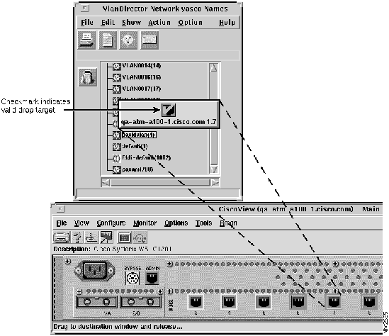
Step 1 Drag the port from CiscoView or the VlanDirector Device Ports window to the selected VLAN name in the Names window.
- To drag from CiscoView, do the following as shown in Figure 4-4:
- Launch CiscoView for the device that contains the ports you want to place in the new VLAN. To launch CiscoView, double-click the device in any view in which the device is displayed, or select Action>Launch CiscoView in the Names window, and select the device from the displayed list of devices. Locate the port or ports you want to add to the new VLAN. Using the middle mouse button, (the left mouse button on NT systems), drag the port to the Names window as shown in Figure 4-3.
- On the CiscoView display, select the ports you want to include in the VLAN. Determine that the ports you want to include in the VLAN are available. To do this, check your records or the planning table that you created in Chapter 2 for other port configurations that might have taken place outside of VlanDirector.
- To drag from a VlanDirector Device Ports window, do the following:
- Launch the Device Ports window from the device pop-up menu in the Network Topology window. To display the popup menu, press and hold down the right mouse button.
-
Figure 4-3 : Drag-and-Drop from CiscoView to the Names Window
-
Figure 4-4 : Dragging a Port from the Device Ports Window to the Names Window
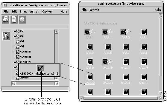
The VLAN Ports window displays the ports in the newly added VLAN.
For help on selecting or dragging and dropping ports, see "Using Drag-and-Drop" in Chapter 3.
Naming VLANs
When you assign a VLAN name in VlanDirector, you specify only the end part of the name. The full VLAN name is the name you specify in the VlanDirector Create Names Entry window in addition to the full folder name.
If the VLAN name marketing is in a folder called groups, the full VLAN name is .:groups:marketing.
The first character (.) represents the root folder. The second character (:) separates folders and names. When using VlanDirector, you do not need to enter or use the full VLAN name, but you need to recognize it, because some VlanDirector windows, such as the VLAN Ports window, display the full name.
Folder names and VLAN names together cannot exceed 32 alphanumeric or symbolic characters, including separator characters. You can use both uppercase characters and lowercase characters, but no spaces.
Whenever VlanDirector displays VLAN names in the VLAN Ports window, it includes the folder, or full path name of the VLANs. You can have a folder or VLAN name of one character or symbol. Case is significant.
VLANs are the endpoint of the name tree, so you cannot nest them. You can, however, nest folders.
VlanDirector displays the VLAN index number in parenthesis next to each VLAN name. This is useful if your network includes switches or other devices such as sniffers that use only VLAN index numbers and not names to identify VLANs.
Bridging Between VLANs
If your network includes both Ethernet and FDDI VLANs , you can create an FDDI VLAN to bridge to an Ethernet VLAN or create an Ethernet VLAN to bridge to an FDDI VLAN. You can also configure existing VLANs to bridge between each other.
Creating an Ethernet VLAN to Bridge to an FDDI VLAN
To create an Ethernet VLAN that bridges to an FDDI VLAN, follow these steps:
Step 1 Display the Names window.
Step 2 In the Names window, select a folder icon. If you are creating a VLAN for the first time, only one folder icon exists. This folder is called the root folder and is located in the top left corner of the window pane shown in Figure 4-1. You can create a single VLAN name or create a folder to contain more than one VLAN name. This example shows how to create a single name.
Step 3 In the Names window, select Action>Create VLAN or Folder, or click the Create VLAN icon in the tool bar.
- The VlanDirector Create Names Entry window is displayed.
Step 4 In the Name field, specify the name of the new VLAN. For example, enter mktg to specify mktg as the name of the new VLAN. Folder names and VLAN names together cannot exceed 32 alphanumeric or symbolic characters.
- For a list of invalid characters in VLAN names or folders, see Naming VLANs later in this chapter. You can use both uppercase and lowercase characters, but no spaces.
Step 5 In the Type field, click the Ethernet radio button to indicate the type of VLAN you are creating.
Step 6 You can, optionally, enter text in the Purpose and Description fields but this is not required. For example, you could specify the following in the purpose field:
The Marketing VLAN has a heavy bandwidth requirement.
- You could specify the following in the Description field:
The Marketing VLAN includes all marketing employees on the first, second, and third floors of Building B.
- If you specify information in the Purpose and Description fields, the Show Purpose and Show Description fields in the VLAN reports displays the specified purpose and description whenever you display a VLAN report.
Step 7 In the VlanDirector Create Names Entry window, click the Advanced Button.
- The VlanDirector Advanced VLAN Parameters Window is displayed as shown in Figure 4-5.
Figure 4-5 : VlanDirector Advanced VLAN Parameters Window
-
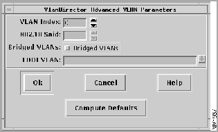
Step 8 In the VLAN Index field, specify a VLAN index. You can enter a number for the index or click the Compute Defaults button to have the system automatically assign a VLAN index.
Step 9 In the 802.10 SAID field, enter the SAID (Source Address Identifier) number of the FDDI VLAN. Enter a number from 1 to 2147483647, or click the Compute Defaults button to have the system automatically assign a number to the VLAN. If you have a server connected to the FDDI link that supports the 802.10 protocol, you will probably want to assign the SAID number and not have the system assign it automatically.
- It is recommended that the SAID number of the FDDI VLAN be identical to the VLAN Index of the Ethernet VLAN to which the FDDI VLAN is bridging.
Step 10 In the Bridged VLANs field, select Bridged VLANs, if not already selected.
Step 11 In the FDDI VLAN field, specify the name of the Ethernet VLAN to which this FDDI VLAN should bridge. Choose an existing one from the pull-down list or specify the name of a new VLAN. If you specify a VLAN name that does not exist, VlanDirector creates a new VLAN with that name.
Step 12 Click OK on the Advanced VLAN Parameters window.
Step 13 Click OK on the VlanDirector Create Names Entry window.
Creating an FDDI VLAN to Bridge to an Ethernet VLAN
To create an FDDI VLAN that bridges to an Ethernet VLAN, perform these steps:
Step 1 Display the Names window.
Step 2 In the Names window, select a folder icon. If you are creating a VLAN for the first time, only one folder icon exists. This folder is called the root folder and is located in the top left corner of the window pane, as shown in Figure 3-1. You can create a single VLAN name or create a folder to contain more than one VLAN name. This example shows how to create a single name.
Step 3 In the Names window, select Action>Create VLAN or Folder, or click the Create VLAN icon in the Tool Bar.
- The VlanDirector Create Names Entry window is displayed.
Step 4 In the Name field, specify the name of the new VLAN. For example, enter mktg to specify mktg as the name of the new VLAN. Folder names and VLAN names together cannot exceed 32 alphanumeric or symbolic characters.
- For a list of invalid characters in VLAN names or folders, see Naming VLANs and Folders earlier in this chapter. You can use both uppercase and lowercase characters, but no spaces.
Step 5 In the Type field, click the FDDI radio button to indicate the type of VLAN you are creating.
Step 6 You can, optionally, enter text in the Purpose and Description fields but this is not required. For example, you could specify the following in the purpose field:
The Marketing VLAN has a heavy bandwidth requirement.
- You could specify the following in the Description field:
The Marketing VLAN includes all marketing employees on the first, second, and third floors of Building B.
- If you specify information in the Purpose and Description fields, the Show Purpose and Show Description fields in the VLAN reports displays the specified purpose and description whenever you display a VLAN report.
Step 7 In the VlanDirector Create Names Entry window, click the Advanced button.
- The VlanDirector Advanced VLAN Parameters Window is shown in Figure 4-6.
Figure 4-6 : Advanced VLAN Parameters Window
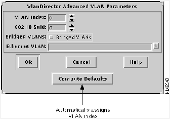
Step 8 In the VLAN Index field, specify a VLAN index. You can enter a number for the index, or click the Compute Defaults button to have the system automatically assign a VLAN index.
Step 9 In the 802.10 SAID field, enter the SAID number of the FDDI VLAN. Enter a number from 2-1000, or click the Compute Defaults button to have the system automatically assign a number to the VLAN. If you have a server connected to the FDDI link that supports the 802.10 protocol, you will probably want to assign the SAID number and not have the system assign it automatically.
- It is recommended that the SAID number of the FDDI VLAN be identical to the VLAN Index of the Ethernet VLAN to which the FDDI VLAN is bridging.
Step 10 In the Bridged VLANs field, select Bridged VLANs, if not already selected.
Step 11 In the Ethernet VLAN field, specify the name of the Ethernet VLAN to which this FDDI VLAN should bridge. Choose an existing one from the pull-down list, or specify the name of a new VLAN. If you specify a VLAN name that does not exist, VlanDirector creates a new VLAN with that name.
Step 12 Click OK in the Advanced VLAN Parameters window.
Step 13 Click OK in the VlanDirector Create Names Entry window.
Modifying VLANs
After you have created VLANs according to the desired configuration for your network, you will frequently need to modify existing VLANs to accommodate network changes such as user moves and varying traffic loads.
Moving Ports Among VLANs
To move ports from one VLAN to another, follow these steps:
Step 1 In the Names window, select the VLAN from which you want to move ports.
Step 2 On the CiscoView display or in the Device Ports window, select the ports that you want to move to the destination VLAN name in the Names window.
Step 3 Drag and drop the ports from the CiscoView or Device Ports display to the destination VLAN name in the Names window.
Merging VLANs
When you merge two VLANs, you make two existing VLANs into one.
To merge two VLANs, do the following:
In the Names window, drag the VLAN name of one of the VLANs to the name of the second VLAN.
The name of the merged VLAN is the name of the target VLAN.
Renaming a VLAN
Use the Find/Replace window to rename a VLAN. For example, to replace the VLAN name Marketing1 with the VLAN name Finance, do the following:
Step 1 In the Names window, select the VLAN or folder to rename.
Step 2 In the Names window, select Edit>Find/Replace. The VlanDirector Find/Replace window is displayed as shown in Figure 4-7.
Figure 4-7 : VlanDirector Find/Replace Window
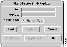
Step 3 In the Find field, enter the name Marketing1, or the VLAN name you want to change.
Step 4 In the Replace field, enter Finance, or the new VLAN name.
Step 5 Click Find.
- The VLAN name that you want to change is selected in the Names window. In this example, the VLAN name is Marketing 1.
Step 6 Click Replace.
The old VLAN name is replaced with the new name in the names window. In this example, the new name is Finance.
Renaming Multiple VLANs
Sometimes you might find it useful to rename a group of VLANs. For example, you might want to change the names of the following VLANs:
domain1
domain2
domain3
domain4
domain 5
to the following names
group1
group2
group3
group4
group5
To do this, do the following:
Step 1 In the Names window, select the VLAN or folder to rename.
Step 2 In the Names window, select Edit>Find/Replace. The VlanDirector Find/Replace window is displayed.
Step 3 In the Find field, enter domain, or any part of the VLAN name that is common to all the VLAN names to be changed.
Step 4 In the Replace field, enter group, or any part of new VLAN name that is common to all the VLAN names to be changed.
Step 5 Click Find.
Step 6 Click Replace All.
The old VLAN names are replaced with the new names in the Names window.
Searching for a VLAN
To find a VLAN Name, do the following:
Step 1 In the Names window, select the root folder.
Step 2 In the Names window, select Edit>Find/Replace. The VlanDirector Find/Replace window is displayed.
Step 3 In the Find field, enter the name or part of the name of the VLAN you want to find.
Step 4 Click Find.
Step 5 The searched for VLAN name is displayed in the Names window (in this example, Marketing1), and any views that are currently open display information for that VLAN. If the displayed VLAN is not the VLAN that you are searching for, click Find Next until you find the VLAN you want or there are no more to find.
Deleting VLAN and VLAN Components
You can remove a port or device from a VLAN, remove a link from a VLAN, or delete a VLAN or folder. You cannot delete the default VLAN or delete link ports from the default VLAN, but can move them to another VLAN.
Deleting a Port from a VLAN
You can remove a port from a VLAN configuration. When you delete a port from a VLAN, the port is disabled and no longer belongs to any VLAN. The disabled port is displayed in the Device Ports window in the color " brown." To remove a port from a VLAN, follow these steps:
Step 1 In the Names window, select the name of the VLAN, from which you want to delete a port or ports.
Step 2 Open the VlanDirector Ports window or display CiscoView for the device containing the port or ports.
Step 3 Select the port or ports you want to delete from the VLAN Ports window or from a CiscoView display of the device containing the port or ports.
Step 4 Drag the port or ports to the trash can icon in the Names window. Deletions and additions can be undone using the Undo Changes window. Click on the trash can icon to display the Undo Changes window.
Step 5 The system prompts you to confirm that you want to delete the port.
Step 6 Click OK to confirm that you want to delete the port or ports.
The port or ports are disabled and no longer belong to any VLAN.
When dragging an item to the trash can, make sure that you place the arrowhead of the pointer in the trash can, and not just the icon that you are dragging.
Deleting a VLAN or Folder
Deleting a VLAN means that you disable all ports in the VLAN. To delete a VLAN or a folder containing multiple VLANs from the Names window, do the following:
- To delete a VLAN, select the VLAN to be deleted in the Names window and drag it to the trash can icon. VlanDirector disables all ports in the VLAN. They no longer belong to any VLAN.
- To delete a folder, in the Names window use the middle mouse button to select and drag the folder icon to the trash can icon. VlanDirector deletes the folder name and disables all ports in all VLANs contained in the folder.
VlanDirector does not warn you if the folder is not empty. Changes can be undone using the Undo Changes window. Launch the Undo Changes window by clicking the trash can icon.
Deleting a Switch from a VLAN
Deleting a switch means that you remove the switch and consequently all its user ports from a VLAN. If you do not want to remove all the ports, follow the steps for deleting a port from a VLAN.
To delete a switch, follow these steps:
Step 1 In the Names window, select the name of the VLAN from which you want to delete a switch. Select only one name.
Step 2 Open the VLAN Topology or the VLAN Devices window.
Step 3 Select the switch(s) you want to delete in either the VLAN Topology or VLAN Devices window.
Step 4 Drag the selection to the trash can in the Names window. Deletions and additions can be undone using the UNDO Changes window. VlanDirector prompts you to confirm that you want to remove the switch from the VLAN.
The dragged switch and all ports that were part of the selected VLAN are removed from the VLAN. All ports deleted from the VLAN are disabled and belong to no VLAN.
Configuring Links
Adding a link to a VLAN configures connections between two devices to provide a path for traffic on that VLAN.
When you delete a link that is carrying more than one VLAN, you remove the selected VLAN from the link, unless it is the default VLAN. You cannot remove the default VLAN from the link.
You cannot delete a link port.
Links on switches running VTP are automatically configured to forward packets for VLANs, so you do not have to perform any configuration in VlanDirector to make this happen.
If your network is not using VTP or some switches on it are not using VTP, VlanDirector prompts you to select from a list of links whenever you add a new device to a VLAN.
In both VTP- and non-VTP-supported networks, you can manually add and delete links as described here.
When you add a link to a VLAN, the link is enabled to carry packets of that VLAN. When you delete a link from a VLAN, it is disabled from carrying packets of that VLAN. If several links between two devices are enabled to carry packets for a VLAN, the Spanning Tree Protocol determines which link actually carries packets for that VLAN and blocks the other links for that VLAN.
If the Spanning Tree Protocol is enabled, you can view the currently forwarding links and configure links to perform load-sharing across parallel links.
Adding a Link
To add a link to a VLAN, follow these steps:
Step 1 In the Names window, select the name of the VLAN to which you want to add links. Select only one name.
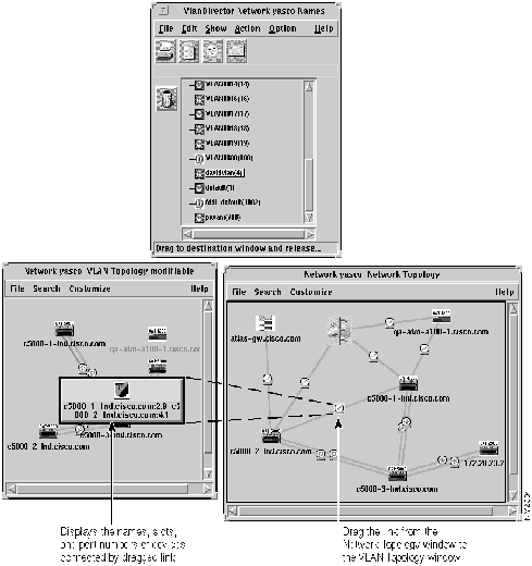
Step 2 In the Network Topology window, select the links you want to add to the VLAN. Select a link by selecting the link icon (medallion) located in the center of the link.
Step 3 Using the middle mouse button (the left mouse button on NT systems), drag and drop the selection from the Network Topology window to a VLAN name in the Names window, the VLAN Topology, the VLAN Devices, or the VLAN Ports window. As you drag, link information is displayed. The example in Figure 4-8 shows a link being dragged from the Network Topology window to the VLAN Topology window.
The link is now configured to carry traffic for the selected VLAN.
Figure 4-8 : Adding a Link to a VLAN
Deleting a Link
Deleting a link severs connections between devices for that VLAN.
You cannot directly delete link ports from a VLAN, but you can delete the link that uses them. If deleting a link leaves the VLAN disconnected, the VLAN topology window shows a device with no links connecting it to the other devices in the VLAN.
To delete a link, follow these steps:
Step 1 In the Names window, select the VLAN name from which you want to remove links. Select only one name.
Step 2 Open the VLAN Topology window, and select the links you want to remove.
Step 3 Drag the links to the trash can icon in the Names window. VlanDirector prompts you to confirm that you want to delete the link. Deleted links can be restored by using the UNDO Changes window.
The selected links are deleted.
Load Sharing along Parallel Links
If a VLAN includes devices that are connected by parallel links and Spanning Tree is enabled, Spanning Tree determines which link should forward packets for each VLAN at a given time based on lowest cost and highest priority.
If you do not specify load sharing and you have not modified the default network settings, Spanning Tree will choose one of the parallel links to carry all VLANs between the two switches.
You can share the load on the parallel links in the following ways:
- Manually remove all VLANs from the links on which they are normally supposed to flow.
- Leave all VLANs enabled on all links and use the Make Preferred command to let Spanning Tree choose which link should forward packets.
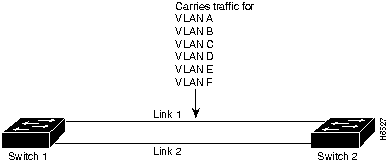
In the example shown in Figure 4-9 link 1 and link 2 are parallel links between switch 1 and switch 2. Spanning Tree determined that link 1 is forwarding packets for VLAN A and VLAN B, VLAN C, VLAN D, VLAN E, and VLAN F.
Figure 4-9 : Sample Link Configuration Before Load Sharing
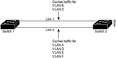
This might not be the most optimal situation for your network. For example, if VLAN A is a small VLAN with very little traffic, and VLAN C is a very large VLAN with very heavy traffic, you might want to redistribute the load so that link 1 carries traffic for VLAN B and C and that link 2 carries traffic for VLAN A, VLAN D, VLAN E, and VLAN F. This is called load sharing and VlanDirector enables you to do this in the following circumstances:
- Parallel links exist between the VLANs.
- One or both links in the set carry multiple VLANs.
- The links have an equal Spanning Tree Protocol cost.
Figure 4-10 : Sample Link Configuration After Load Sharing
Selecting "Preferred" Links
If you wish to distribute traffic along parallel links, you can do so by selecting the link that you want to share the traffic load, and then specifying it as the preferred link for a selected VLAN or VLANs. To implement the load sharing changes shown in Figure 4-10, you will need to make link 1 the preferred link for VLAN B and C and link 2 the preferred link for VLANs A, D, E, and F, as shown in the following procedure.
To make link1 the preferred link for VLANs B and C, follow these steps:
Step 1 In the Names window, select the Name of the VLANs for which the preferred link is being specified, in this case, VLANs B and C.
Step 2 In the VLAN Topology Window, select the link that you want to forward packets, in this example, link1. To select the link, click the left mouse button on the link icon. To select more than one link, click the left mouse button and hold down the Shift key.
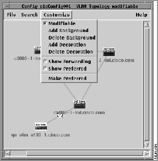
Step 3 Select Customize>Make Preferred. The selected link flashes if you have also selected Show Preferred.
In the example, link 1 is now enabled to carry packets for VLAN B and C.
To make link 2 the preferred link for VLANs A, D, E, and F, do the following.
Step 1 In the Names window, select the Name of the VLANs for which the preferred link is being specified, in this case, VLANs A, D, E, and F.
Step 2 In the VLAN Topology Window, select the link that you want to forward packets, in this example, link 2. To select the link, click the left mouse button on the link icon. To select more than one link, hold down the Shift key and click the left mouse button.
Step 3 Select Customize>Make Preferred. The selected link flashes if the Show Preferred option is selected.
Step 4 In the example, link 2 is now enabled to carry packets for VLANs A, D, E, and F.
Displaying the Forwarding Links in an STP Environment
When working with VlanDirector, you can at any time display the link currently enabled to forward packets for one or more VLANs.
To display the links that are currently forwarding for the selected VLANs, from the VLAN Topology window, select Customize>Show Forwarding, as shown in Figure 4-11.
Figure 4-11 : Displaying the Forwarding Path
The path that has been enabled to forward packets for the selected VLANs is highlighted in black (by default) and begins to flash. The other link or links are enabled but are not forwarding packets.
Displaying the Preferred Links
If you have changed any forwarding links using the Make Preferred command, and you later want to display the preferred links, do the following:
In the VLAN Topology window, select Customize>Show Preferred. The links configured as "Preferred" flash.
Usually, the Make Preferred and Show Preferred links are the same. However, if a problem occurred in the network, for example, a link is down, the Make Preferred and Show Preferred links might be different.
Saving Changes and Configurations
Changes to the known network are automatically saved in the VlanDirector database under the name of the Known Network that you specified when you started VlanDirector. To restart VlanDirector using the same known network, select Option>Save Program Preferences before you quit VlanDirector.
You can also save copies (configurations) of the known network. Known networks and configurations are described in detail in Chapter 5.
Quitting VlanDirector
To quit VlanDirector, from the Names window select File>Exit.
The VlanDirector windows close and the application quits.
Copyright 1988-1996 © Cisco Systems Inc.