|
|

Overview of the
Cisco 2517 and Cisco 2519
The Cisco 2517 and Cisco 2519 combines Token Ring hub and router capabilities with a built-in Integrated Services Digital Network (ISDN) Basic Rate Interface (BRI).
Both units incorporate an intelligent, workgroup Token Ring hub with sophisticated internetwork connectivity via its built-in WAN interfaces and the Cisco Internetwork Operating System (Cisco IOS software).
These hubs provide in a single unit the capabilities of a Token Ring unshielded twisted pair (UTP) concentrator, an intelligent Simple Network Management Protocol (SNMP) internetwork router, and an ISDN terminal adapter.
The hubs have the following features:
Software for the management card is included in firmware that is accessible through the management card console port.
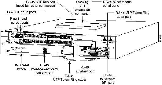
Figure 1-1 shows the Cisco 2517 12-port hub, and Figure 1-2 shows the Cisco 2519 24-port hub.
Figure 1-1 Cisco 2517 12-port Hub
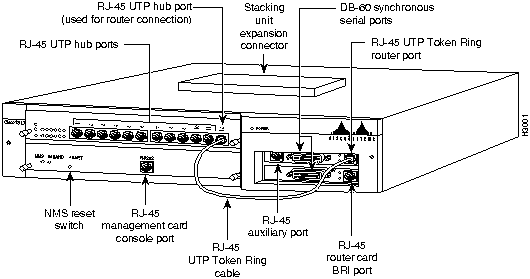
Figure 1-2 Cisco 2519 24-port Router/Hub
Warning The ISDN connection is regarded as a source of voltage that should be inaccessible to user contact. Users should not attempt to tamper with or open any public telephone operator (PTO)--provided equipment or connection hardware. Any hardwired connection (other than by nonremovable, connect-one-time-only lug) must be made only by PTO staff or suitably trained engineers. Translated versions of this warning are in the appendix "Translated Safety Warnings."
![]()
Warning The ports labeled "Ethernet," "Token Ring," and "AUX" are safety extra-low voltage (SELV) circuits. SELV circuits should only be connected to other SELV circuits. Because the BRI circuits are treated like telephone-network voltage, avoid connecting the SELV circuit to the telephone network voltage (TNV) circuits. Translated versions of this warning are in the appendix "Translated Safety Warnings."
![]()
The hub port card is a slide-in card in one of the following configurations:
Figure 1-2 shows the location of the hub port card in the chassis. Figure 1-3 shows the front of the 12-port Token Ring hub port card, and Figure 1-4 shows the 24-port Token Ring hub port card.
Figure 1-3 Cisco 2517 12-port Token Ring Hub Port Card
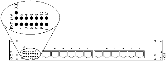
Figure 1-4 Cisco 2519 24-port Token Ring Hub Port Card
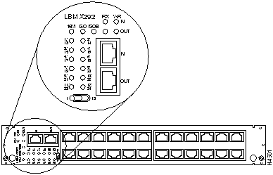
The Token Ring hub port cards have an LED for the ring speed, port 1 mode, isolation mode, and each of the Token Ring hub ports. The 24-port hub port card has a toggle switch to display different banks of ports.
Table 1-1 lists and describes the Cisco 2517 LEDs. Table 1-2, Table 1-3, and Table 1-4 list and describe the Cisco 2519 LEDs.
Table 1-1 Cisco 2517 12-port Token Ring Hub Port Card LEDs
| LED | Status | Description |
|---|---|---|
| EXT | On | Port 1 is set for hub-to-hub link. |
| Off | Port 1 acts as a regular Token Ring port | |
| 16M | On | The ring speed is set to 16 Mbps. |
| Off | The ring speed is set to 4 Mbps | |
| ISOL | On | The hub port card is isolated from the backplane |
| Off | The hub port card is connected to the backplane | |
| Port LEDs | Green | An active station is connected to the port and is fully operational |
| Red | An active station is connected to the port, and disconnected from the ring | |
| Off | No active station is connected |
Table 1-2 Cisco 2519 24-port Token Ring Hub Port Card LEDs
| LED | Status | Description |
|---|---|---|
| 16M | On | Ring speed is set to 16 Mbps |
| Off | Ring speed is set to 4 Mbps | |
| ISOL (group isolation) The LED toggle switch determines whether the status for ports 1-12 or ports 13-24 are displayed. |
On | The ports indicated with the toggle switch are isolated from the backplane |
| Off | The ports indicated with the toggle switch are in normal mode |
|
| ISOB (backplane isolation) | On | The entire module is isolated from the backplane |
| Off | The module is connected to the backplane | |
| Port LEDs The LED toggle switch determines whether the status for ports 1-12 or ports 13-24 are displayed. |
Green | An active station is connected to the port and is fully operational |
| Red | An active station is connected to the port, but is disconnected from the ring | |
| Off | No active station is connected |
Table 1-3 and Table 1-4 show the meaning of the Ring In and Ring out LEDs on the Cisco 2519. To read these tables, pick the state of the RX LED, and pick a state for the WR LED. Where the row and column intersect, read the meaning of the RX LED and WR LED combination.
Table 1-3 Cisco 2519 Ring In and Ring Out LED Indicators: MAU Mode
RX LED |
WR LED | ||
|---|---|---|---|
| Green | Red | Off | |
| Green | Data rate error | Remote repeater module forced wrap mode | Data rate is valid |
| Red | Not applicable | IN port: not applicable OUT port: port is isolated (wrapped) by the network management station |
Not applicable |
| Off | Not applicable | Port wrapped, no signal received | Not applicable |
Table 1-4 Cisco 2519 Ring In and Ring Out LED Indicators: Repeater Mode
RX LED |
WR LED | ||
|---|---|---|---|
| Green | Red | Off | |
| Green | Data rate error | Operating mode error. This port is in MAU mode but the remote port is in repeater mode | Data rate is valid |
| Red | Not applicable | IN port: not applicable OUT port: port is isolated (wrapped) by the network management station |
Not applicable |
| Off | Cable fault | Port wrapped, no signal received | IN port: Not applicable OUT port: no signal is circulating on the redundant path, assuming that the IN port has a valid data rate |
A bank of DIP switches and a port impedance jumper are located on the hub port cards. See the section "Setting Hub Port Card DIP Switches and Jumper" in the appendix "Cisco 2517 and Cisco 2519 Router/Hub Maintenance" for more information.
The management card is a removable card tray in the hub that has an integrated PC-AT compatible chip set and ISA bus. The router card and daughter card are inserted into the two ISA slots.
Figure 1-5 shows the front panel of the management card, and Table 1-5 describes the LEDs.
Figure 1-5 Management Card Front Panel
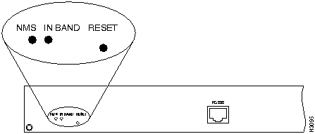
Table 1-5 Management Card LEDs and Reset Button
| LED/Button | Description |
|---|---|
| NMS | Indicates that the management card is active. |
| IN BAND | When blinking, data is being transmitted or received over in-band communication to the router. |
| RESET | Push this button to reset the management card and SNMP agent. |
Figure 1-6 shows a top view of the management card.
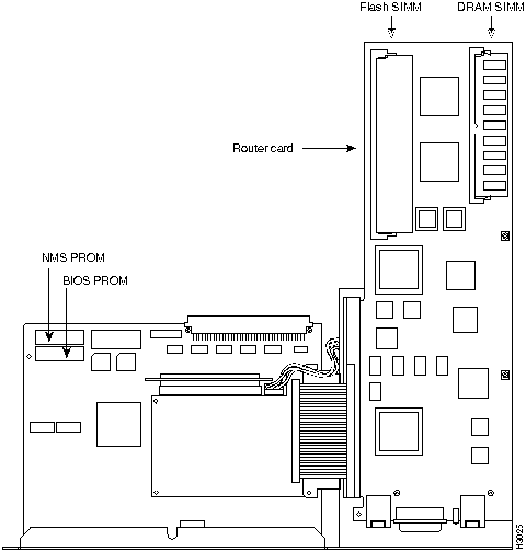
No jumpers or DIP switches on the management card are user configurable. Remove the management card to replace ROMs or service the router card. See the appendix "Cisco 2517 and Cisco 2519 Router/Hub Maintenance" for management card ROM replacement procedures, or the appendix "Router Card Maintenance" for router card service procedures.
Use the console port on the management card to access the management card's firmware, as well as the router card software. See the section "Connecting a Terminal or PC to the Router/Hub Console Port" in the chapter "Installing the Router/Hub" for more information.
You can also configure the port for a SLIP or PPP connection to a PC running the Cisco Hub/Ring Manager. See the chapter "Configuring the Router/Hub SNMP Agent with SPSET" in the Cisco Hub/Ring Manager for Windows Getting Started Guide on Cisco Connection Documentation CD-ROM or the printed publication for more information.
The router card is a full-featured, multiprotocol router card installed in the chassis's ISA slots. The router card has the following features:
The RJ-45 asynchronous auxiliary port on the router is used to connect to a terminal or modem.
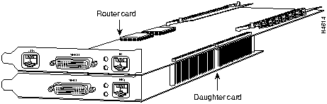
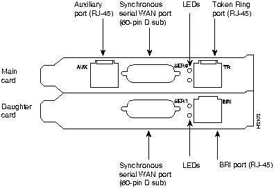
Figure 1-7 shows the layout of the router card, and Figure 1-8 shows the router card with a daughter card.
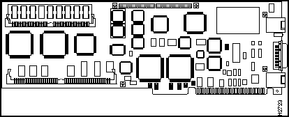
Figure 1-8 Router Card with a Daughter Card
The router card has the following ports:
Warning Hazardous network voltages are present in the BRI cable. If you detach the BRI cable, detach the end away from the AccessPro card first to avoid possible electric shock. Network hazardous voltages also are present on the system card in the area of the BRI port (RJ-45 connector), regardless of when power is turned off. Translated versions of this warning are in the appendix "Translated Safety Warnings."
![]()
Figure 1-9 Token Ring Router Card Ports
The integrated management software allows you to monitor and control your entire network from a central site.
Physical level management includes port monitor and control for port activity, status, and repeater ports. MAC layer management includes the following features:
You configure the router card first by accessing the Cisco IOS software through the management card's console port. The IP address of the router/hub management SNMP agent is assigned automatically with PCbus address resolution protocol (ARP), and is based on the IP address you assigned to the router's PCbus.
See the chapter "Configuring the Router/Hub SNMP Agent with SPSET" for more information.
Table 1-6 lists the specifications for the Cisco 2517 and Cisco 2519.
Table 1-6 Cisco 2517 and Cisco 2519 Hub Specifications
| Specification | Description |
|---|---|
| Dimensions (H x L) | 3.0 x 19.0'' (7.62 x 48.26 cm) |
| Input voltage and frequency | Cisco 2517: 115/230 VAC, 60/50 Hz Cisco 2519: 100--120/200-240 VAC, 60/50 Hz |
| Output power | 20.0A maximum @ 5V |
| Power dissipation | 100W maximum |
| Token Ring interfaces | Cisco 2517: 12 IEEE 802.5 (RJ-45) Cisco 2519: 24 IEEE 802.5 (RJ-45) |
| Serial interfaces | 1 EIA/TIA-232 |
| Operating environment | 50 to 95°F (10 to 35°C) |
| Nonoperating temperature | --4 to 185°F (--20 to 85°C) |
| Operating humidity | 5 to 95%, noncondensing |
| Regulatory Compliance | This product conforms to FCC Class A compliance requirements, and other compliance as outlined in the Cisco 2517 and Cisco 2519 Public Network Certification document that shipped with your order. |
Table 1-7 lists the technical specifications for the router card.
Table 1-7 Router Card Specifications
| Specification | Description |
|---|---|
| Dimensions (H x L) | 4.8 x 13.3'' (12.2 x 33.8 cm) |
| Power requirements | 3.0A @ 5V, 0.5A @ ±12V |
| Processor | 20-MHz Motorola 68EC030 |
| Memory | 2-MB primary memory (DRAM SIMMs, expandable to 6 or 18 MB)4-MB Flash memory (expandable to 16 MB)32-KB NVRAM |
| Network interfaces | 1 BRI and 2 synchronous serial |
| Token Ring interface | 1 IEEE 802.5 (RJ-45) |
| Synchronous serial interfaces | EIA/TIA-232, EIA/TIA-449, V.35, X.21 (NRZ/NRZI(1) and DTE/DCE)EIA-530 (NRZ/NRZI and DTE)All serial cables use a DB-60 chassis connector. |
| BRI | ISDN basic rate (RJ-45) |
| Auxiliary/console port | Asynchronous serial (RJ-45, EIA/TIA-232-compatible) |
| Regulatory Compliance | This product conforms to FCC Class A compliance requirements, and other compliance as outlined in the Cisco 2517 and Cisco 2519 Public Network Certification document that shipped with your order. |
|
|
Copyright 1988-1996 © Cisco Systems Inc.