|
|
Configuration Guidelines for the Cisco 7000 Family
This chapter provides configuration information about the Cisco 7000 family, which includes the following routers:
The information is organized into the following sections:
This section provides tables of options and configuration guidelines for the Cisco 7000 family. Use these tables to fill out the configuration worksheets at the end of this chapter.
| Interface
Processor |
Description | Product Number |
|---|---|---|
| AIP | ATM Interface Processor, TAXI multimode, 100 Mbps | CX-AIP-TM |
| ATM Interface Processor, SONET/SDH multimode, 155 Mbps | CX-AIP-SM | |
| ATM Interface Processor, SONET/SDH single mode, 155 Mbps | CX-AIP-SS | |
| ATM Interface Processor, E3 coaxial, 34 Mbps | CX-AIP-E3 | |
| ATM Interface Processor, DS3 coaxial, 45 Mbps | CX-AIP-DS3 | |
| CIP21 | Channel Interface Processor 2 with single parallel channel | CX-CIP2-PCA1 |
| Channel Interface Processor 2 with dual parallel channel | CX-CIP2-PCA2 | |
| Channel Interface Processor 2 with single ESCON channel | CX-CIP2-ECA1 | |
| Channel Interface Processor 2 with dual ESCON channel | CX-CIP2-ECA2 | |
| Channel Interface Processor 2 with single ESCON channel and single parallel channel | CX-CIP2-ECAP1 | |
| EIP | Ethernet Interface Processor, 2-port | CX-EIP2 |
| Ethernet Interface Processor, 4-port | CX-EIP4 | |
| Ethernet Interface Processor, 6-port | CX-EIP6 | |
| FEIP | Fast Ethernet Interface Processor, 1-port | CX-FEIP1TX |
| Fast Ethernet Interface Processor, 2-port | CX-FEIP2TX | |
| FIP | FDDI Interface Processor, multimode to multimode | CX-FIP-MM |
| FDDI Interface Processor, single-mode to single-mode | CX-FIP-SS | |
| FDDI Interface Processor, multimode to single-mode | CX-FIP-MS | |
| FDDI Interface Processor, single-mode to multimode | CX-FIP-SM | |
| FSIP | Fast Serial Interface Processor, 4-port | CX-FSIP4 |
| FSIP dual-port port adapter (PA), default is 2 | PA-7KF-SPA1 | |
| FSIP E1-G.703/G.704 120-ohm dual port adapter (PA) | PA-7KF-E1/1201 | |
| FSIP E1-G.703/G.704 75-ohm dual PA | PA-7KF-E1/751 | |
| Fast Serial Interface Processor, 8-port | CX-FSIP8 | |
| FSIP dual-port port adapter (PA), default is 2 | PA-7KF-SPA1 | |
| FSIP E1-G.703/G.704 120-ohm dual port adapter (PA) | PA-7KF-E1/1201 | |
| FSIP E1-G.703/G.704 75-ohm dual PA | PA-7KF-E1/751 | |
| HIP | HSSI Interface Processor, 1 high-speed serial port | CX-HIP |
| MIP | MultiChannel Interface Processor, 1-port T1/PRI | CX-MIP-1CT1 |
| MultiChannel Interface Processor, 2-port T1/PRI | CX-MIP-2CT1 | |
| MultiChannel Interface Processor, 1-port E1/PRI, 75 ohm | CX-MIP-1CE1/75 | |
| MultiChannel Interface Processor, 1-port E1/PRI, 120 ohm | CX-MIP-1CE1/120 | |
| MultiChannel Interface Processor, 1-port 75 ohm balanced or 120 ohm unbalanced | CX-MIP-75/120 | |
| MultiChannel Interface Processor, 2-port E1/PRI, 75 ohm | CX-MIP-2CE1/75 | |
| MultiChannel Interface Processor, 2-port E1/PRI, 120 ohm | CX-MIP-2CE1/120 | |
| SMIP | Service Provider MultiChannel Interface Processor, 2 E1 or ISDN PRI ports, 75 ohm unbalanced | CX-SMIP-2CE1/75 |
| Service Provider MultiChannel Interface Processor, 2 E1 or ISDN PRI ports, 75 ohm unbalanced and 120 ohm balanced | CX-SMIP-2CE1/120 | |
| Service Provider MultiChannel Interface Processor, 2 T1 or ISDN PRI ports | CX-SMIP-2CT1 | |
| SSIP | Standard Serial Interface Processor, 8-port | CX-SSIP8 |
| TRIP | Token Ring Interface Processor, 2-port | CX-TRIP2 |
| Token Ring Interface Processor, 4-port | CX-TRIP4 | |
| VIP2 port adapters | VIP2 port adapter with 4 Ethernet ports | PA-4E |
| VIP2 port adapter with 8 Ethernet ports | PA-8E | |
| VIP2 port adapter with 1 Fast Ethernet (FE) port, twisted pair | PA-FE-TX | |
| VIP2 port adapter with 1 FE port, fiber-optic | PA-FE-FX | |
| VIP2 port adapter with 4 Token Ring ports | PA-4T | |
| VIP2 port adapter with 4 EIA-232, EIA-449, EIA-530, V.35, X.21 ports | PA-4R | |
| VIP2 port adapter with 5 Ethernet 10Base-FL ports | PA-5EFL | |
| VIP2 port adapter with 1 FDDI multimode port | PA-F-MM | |
| VIP2 port adapter with 1 full-duplex FDDI multimode | PA-F-SM | |
| VIP2 port adapter with 1 FDDI single-mode port | PA-F-SM | |
| VIP2 port adapter with 1 full-duplex FDDI single-mode | PA-F/FD-SM | |
| VIP2 port adapter with 1 HSSI port | PA-1H | |
| VIP2 port adapter with 2 HSSI ports | PA-2H | |
| Investment
Protection Program (IPP) |
Interface processor upgrades | See Table 110 in the chapter "Interface Processors and Port Adapters for the Cisco 7000 Family" |
The following table lists the port adapters common to the VIP2 interface processor for the Cisco 7000 series and Cisco 7500 series routers and the Cisco 7200 series routers.
Table 112 : VIP2 and Cisco 7200 Series Port Adapters
| Description | Product Number |
|---|---|
| 4 Ethernet 10BaseT ports | PA-4E |
| 8 Ethernet 10BaseT ports | PA-8E |
| 1 Fast Ethernet port | PA-FE-T, PA-FE-FX |
| 4 synchronous serial ports supporting EIA/TIA-232, EIA/TIA-449, EIA-530, X.21, and V.35 | PA-4T |
| 4 Token Ring ports | PA-4R |
| 5 Ethernet 10BaseFL ports | PA-5EFL |
| 1 FDDI multimode | PA-F-MM |
| 1 FDDI single-mode | PA-F-SM |
| 1 FDDI multimode, full duplex | PA-F/FD-MM |
| 1 FDDI single-mode, full duplex | PA-F/FD-SM |
| 1 HSSI | PA-1H |
| 2 HSSI | PA-2H |
Table 113 outlines the minimum VIP2 hardware configurations for port adapters supported by the VIP2 architecture.
Table 113 : Minimum VIP2 Hardware Configurations
| Slot 1 | ||||||||||
|---|---|---|---|---|---|---|---|---|---|---|
| Blank | Ethernet 8E | Ethernet 4E | Ethernet 5EFL | Ethernet FE-TX | Ethernet FE-FX | Token Ring 4R1 | Serial
4T |
FDDI
1F2 |
||
| Slot 0 | Blank | VIP2-10 | VIP2-10 | VIP2-10 | VIP2-10 | VIP2-10 | VIP2-10 | VIP2-20 | VIP2-10 | VIP2-20 |
| Ethernet 8E | VIP2-10 | VIP2-10 | VIP2-10 | VIP2-10 | VIP2-10 | VIP2-10 | VIP2-20 | VIP2-10 | VIP2-20 | |
| Ethernet 4E | VIP2-10 | VIP2-10 | VIP2-10 | VIP2-10 | VIP2-10 | VIP2-10 | VIP2-20 | VIP2-10 | VIP2-20 | |
| Ethernet
5EFL |
VIP2-10 | VIP2-10 | VIP2-10 | VIP2-10 | VIP2-10 | VIP2-10 | VIP2-20 | VIP2-10 | VIP2-20 | |
| Ethernet
FE-TX |
VIP2-10 | VIP2-10 | VIP2-10 | VIP2-10 | VIP2-10 | VIP2-10 | VIP2-20 | VIP2-10 | VIP2-20 | |
| Ethernet
FE-FX |
VIP2-10 | VIP2-10 | VIP2-10 | VIP2-10 | VIP2-10 | VIP2-10 | VIP2-20 | VIP2-10 | VIP2-20 | |
| T. Ring 4R1 | VIP2-20 | VIP2-20 | VIP2-20 | VIP2-20 | VIP2-20 | VIP2-20 | VIP2-20 | VIP2-20 | VIP2-20 | |
| Serial 4T | VIP2-103 | VIP2-103 | VIP2-103 | VIP2-103 | VIP2-103 | VIP2-103 | VIP2-20 | VIP2-103 | VIP2-20 | |
| FDDI 1F2 | VIP2-20 | VIP2-20 | VIP2-20 | VIP2-20 | VIP2-20 | VIP2-20 | VIP2-20 | VIP2-20 | VIP2-20 | |
Table 114 lists product numbers that apply to an initial order for a Cisco 7505, Cisco 7507, or Cisco 7513 router. Note that you can order many options as a spare by adding an equal sign (=) to the product number. Refer to a previous chapter, "Cisco 7500 Series," for tables that include product numbers for spares and upgrades.
To order a router, select a base unit and then order specific options listed in Table 114. The base unit comes with a console cable, an auxiliary cable, an RSP, an AC power supply, and a power cord. Default components are included in the price of the base unit.
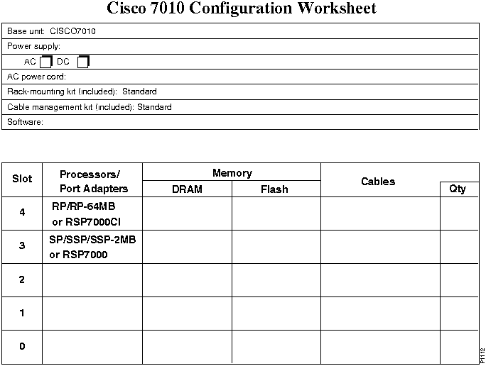
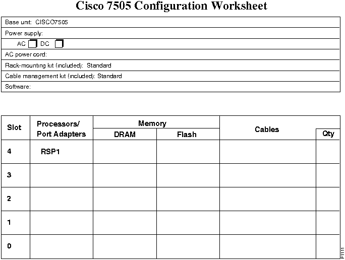
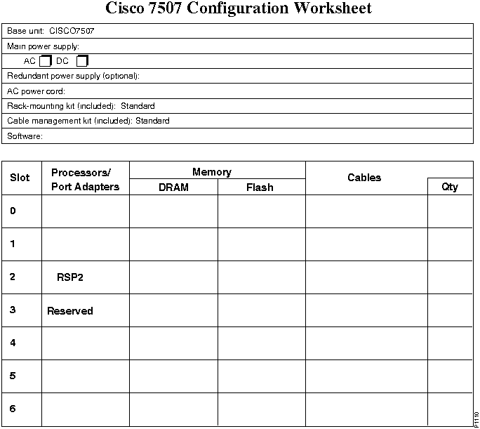
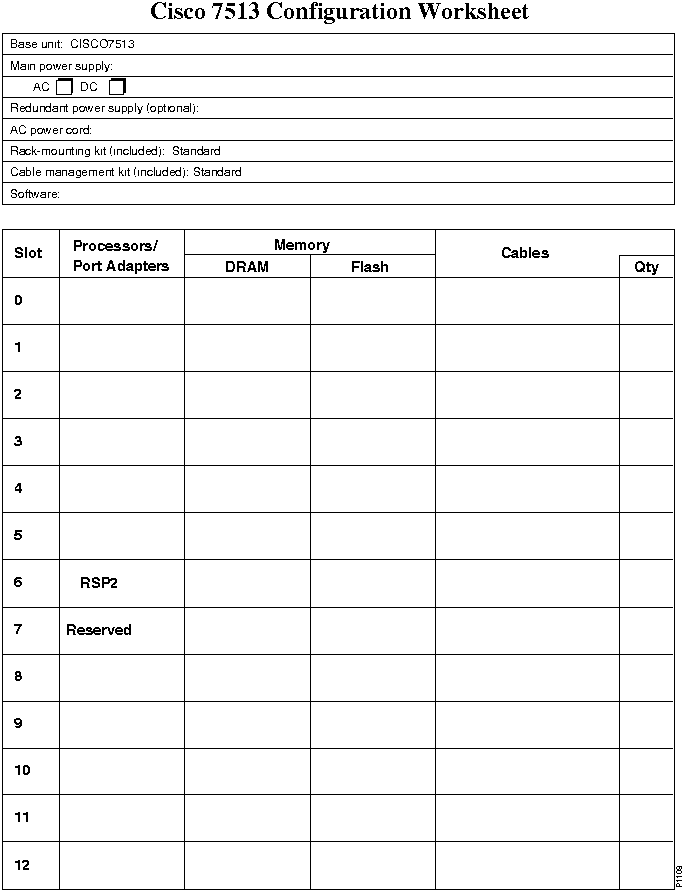
The last pages of this chapter provide worksheets for planning your system.
Table 114 : Cisco 7500 Series Product Numbers
| Description | Product Number |
|---|---|
| Base Unit | |
| Cisco 7505 router (chassis, power supply, fan, RSP1) | CISCO7505 |
| Cisco 7507 router (chassis, power supply, fan, RSP2) | CISCO7507 |
| Cisco 7513 router (chassis, power supply, blower, RSP2) | CISCO7513 |
| Cisco 7505 Power Supply1 | |
| Single DC-input power supply | PWR/5-DC |
| Single AC-input power supply, Australia | PWR/5-ACA= |
| Single AC-input power supply, Europe | PWR/5-ACE= |
| Single AC-input power supply, Italy | PWR/5-ACI= |
| Single AC-input power supply, United Kingdom | PWR/5-ACU= |
| Cisco 7507 Power Supply2 | |
| Single AC-input power supply, U. S. (default) | PWR/7 |
| Single AC-input power supply, Australia | PWR/7-ACA= |
| Single AC-input power supply, Europe | PWR/7-ACE= |
| Single AC-input power supply, Italy | PWR/7-ACI= |
| Single AC-input power supply, United Kingdom | PWR/7-ACU= |
| Single DC-input power supply | PWR/7-DC |
| Dual AC-input power supply | PWR/7/2 |
| Dual DC-input power supply | PWR/7/2-DC |
| Cisco 7513 Power Supply | |
| Single AC-input power supply, U. S. (default) | PWR-7513 |
| Single AC-input power supply, Australia | PWR-7513-ACA= |
| Single AC-input power supply, Europe | PWR-7513-ACE= |
| Single AC-input power supply, Italy | PWR-7513-ACI= |
| Single AC-input power supply, United Kingdom | PWR-7513-ACU= |
| Single DC-input power supply | PWR-7513-DC |
| Dual AC-input power supply | PWR-7513/2 |
| Dual DC-input power supply | PWR-7513/2-DC |
| Processor | |
| Cisco 7505 Route Switch Processor | RSP1 |
| Cisco 7507 and Cisco 7513 Route Switch Processor | RSP23, 4 |
| Flash Memory | |
| 8-MB PCMCIA Flash memory card (default) | MEM-RSP-FLC8M |
| 16-MB PCMCIA Flash memory card | MEM-RSP-FLC16M |
| 20-MB PCMCIA Flash memory card | MEM-RSP-FLC20M |
| DRAM | |
| 8-MB DRAM (upgrade only)5 | MEM-RSP-8M= |
| 16-MB DRAM (default) | MEM-RSP-16M |
| 24-MB DRAM6 | MEM-RSP-24M |
| 32-MB DRAM 7 | MEM-RSP-32M |
| 64-MB DRAM | MEM-RSP-64M |
| 128-MB DRAM | MEM-RSP-128M |
| Boot ROM Upgrade | |
| Boot ROM upgrade8 | ROMMON-RSP2= |
| Interface Processors | |
| Choice of interface processors | See Table 111 |
| AIP Cable | |
| RG-59 coaxial cable with BNC connectors for DS3 and E3 PLIMs | CAB-ATM-DS3/E3= |
| HIP Cables | |
| HSSI, null modem, DTE | CAB-HNUL |
| HSSI, male-to-male | CAB-HSI1 |
| MIP Channelized T1 Cables | |
| DSX1 to CSU BD-15 null | CAB-7KCT1DB15 |
| DSX1 to CSU BD-15 thru | CAB-7KCT1NULL |
| MIP/SMIP Channelized E1 Cables | |
| EI ISDN PRI, 10' | CAB-E1-PRI |
| E1 BNC 75-ohm unbalanced, 5 m | CAB-E1-BNC |
| E1 DB-15 120-ohm balanced, 5 m | CAB-E1-DB15 |
| E1 TWINAX 120-ohm balanced, 5 m | CAB-CAB-EI-TWINAX |
| FSIP/SSIP Cables | |
| X.21 high-density male DTE | CAB-X21MT |
| X.21 high-density female CDE | CAB-X21FC |
| EIA/TIA-449 high-density male DTE | CAB-449MT |
| EIA/TIA-449 high-density female DCE | CAB-449FC |
| V.35 high-density male DTE | CAB-V35MT |
| V.35 high-density female DCE | CAB-V35FC |
| EIA/TIA-232 high-density male DTE | CAB-232MT |
| EIA/TIA-232 high-density female DCE | CAB-232FC |
| EIA-530 high-density male DTC | CAB-530MT |
| E1-G.703/G.704 twinax 120-ohm, balanced, 5 m | CAB-EI-TWINAX |
| E1-G.703/G.704 DB-15 120-ohm, balanced, 5 m | CAB-EI-DB15 |
| E1-G.703/G.704 BNC 75-ohm, balanced, 5 m | CAB-EI-BNC |
| CIP2 Cables | |
| CIP2---Upstream parallel channel interface for CX-CIP2-PCA1, CX-CIP2-PCA2, CX-CIP2-ECAP1 | CAB-PCA-VA |
| CIP2---Downstream parallel channel interface for CX-CIP2-PCA1, CX-CIP2-PCA2, CX-CIP2-ECAP1 | CAB-PCA-VB |
| Spare 78-pin D-shell cable for CIP2 | CAB-PCA-Y= |
| All Other Cables | Customer supplied |
| Investment Protection Program (IPP) | |
| Choice of interface processor upgrades | See Table 110 in the chapter "Interface Processors and Port Adapters for the Cisco 7000 Family" |
| Software | |
| Software Feature Sets | |
| Enterprise | SF75A--11.2.x9 |
| Enterprise and Encryption 40 | SF75AK-11.2.x |
| Enterprise and Encryption 56 | SF75AT-11.2.x |
| Enterprise, VIP/VIP210 | SF75A--11.2.x |
| Enterprise, APPN11 | SF75AN-11.2.x |
| Enterprise, APPN, and Encryption 40 | SF75ANK-11.2.x |
| Enterprise, APPN, and Encryption 56 | SF75ANT-11.2.x |
| Enterprise, APPN, VIP/VIP210 | SF75AN-11.2.x |
| Desktop, IBM | SF75BS-11.2.x |
| Desktop, IBM, and Encryption 40 | SF75BSK-11.2.x |
| Desktop, IBM, and Encryption 56 | SF75BST-11.2.x |
| Desktop, IBM, VIP/VIP210 | SF75BS-11.2.x |
| Desktop, IBM, APPN, VIP/VIP210 | SF75BSN-11.2.x |
| IP only | SF75C-11.2.x |
| IP and Encryption 40 | SF75CK-11.2.x |
| IP and Encryption 56 | SF75CT-11.2.x |
| IP, VIP/VIP210 | SF75C-11.2.x |
| Software Feature Licenses | |
| WAN Packet Protocols (optional) | FR-WPP75 |
| Interdomain Routing (optional)12 | FR-IR75 |
| Netflow Switching | FR-NF75 |
| CIP2 software13 | FR-CIP-TCPOFF, FR-CIP-CSNA |
| VIP/VIP2 software (automatically included with VIP order) | -- |
Table 115 lists product numbers that apply to an initial order for a Cisco 7000 or Cisco 7010 router. Note that you can order many options as a spare by adding an equal sign (=) to the product number. Refer to a previous chapter, "Cisco 7000 Series," for tables that include product numbers for spares and upgrades.
To order a router, select a base unit and then order specific options listed in Table 115. The standard base unit comes with a console cable, an auxiliary cable, an RP, an SP, an AC power supply, and a power cord. Default components are included in the price of the base unit.
The last pages of this chapter provide worksheets for planning your system.
Table 115 : Cisco 7000 Series Product Numbers
| Description | Product Number |
|---|---|
| Base Unit | |
| Cisco 7000 router | CISCO7000 |
| Cisco 7010 router | CISCO7010 |
| Cisco 7000 Power Supply1 | |
| Single AC-input power supply for USA (default) | PWR/7-AC |
| Single AC-input power supply for Australia | PWR/7-ACA= |
| Single AC-input power supply for Europe | PWR-7000-ACE= |
| Single AC-input power supply for Italy | PWR/7-ACI= |
| Single AC-input power supply for United Kingdom | PWR/7-ACU= |
| Dual AC-input power supply | PWR/7/2 |
| Single DC-input power supply2 | PWR/7-DC |
| Dual DC-input power supply2 | PWR/7/2DC |
| Cisco 7010 Power Supply1 | |
| Single AC-input power supply (default) | PWR/5-AC |
| Single AC-input power supply for Australia | PWR/5-ACA= |
| Single AC-input power supply for Europe | PWR/5-ACE= |
| Single AC-input power supply for Italy | PWR/5-ACI= |
| Single AC-input power supply for United Kingdom | PWR/5-ACU= |
| Single DC-input power supply2 | PWR/5-DC= |
| Route Processor (RP) | |
| Route Processor with 16-MB RAM (default) | RP |
| Route Processor with 64-MB RAM3 | RP-64MB |
| Switch Processor (SP/SSP) | |
| Switch Processor (default) | SP |
| Silicon Switch Processor with 512-KB packet memory4 | SSP |
| Silicon Switch Processor with 2-MB packet memory5 | SSP-2MB |
| RP Flash Memory Cards6 | |
| 8-MB Flash memory card with sleeve | MEM-RP-FLC8M |
| 16-MB Flash memory card with metal sleeve | MEM-RP-FLC16M |
| RSP7000 | |
| RSP upgrade kit for the Cisco 7000/7010 | UPG-RSP7000 |
| RSP7000 Flash Memory | |
| 8-MB PCMCIA Flash memory card (default) | MEM-RSP-FLC8M |
| 16-MB PCMCIA Flash memory card | MEM-RSP-FLC16M |
| 20-MB PCMCIA Flash memory card | MEM-RSP-FLC20M |
| RSP7000 DRAM | |
| 8-MB DRAM (upgrade only)7 | MEM-RSP-8M= |
| 16-MB DRAM (default) | MEM-RSP-16M |
| 24-MB DRAM8 | MEM-RSP-24M |
| 32-MB DRAM 9 | MEM-RSP-32M |
| 64-MB DRAM | MEM-RSP-64M |
| 128-MB DRAM | MEM-RSP-128M |
| Interface Processors | |
| Choice of interface processors | See Table 111 |
| AIP Cable | |
| RG-59 coaxial cable with BNC connectors for DS3 and E3 PLIMs | CAB-ATM-DS3/E3= |
| HIP Cables | |
| HSSI, null modem, DTE | CAB-HNUL |
| HSSI, male-to-male | CAB-HSI1 |
| MIP Channelized T1 Cables | |
| DSX1 to CSU BD-15 thru | CAB-7KCT1DB15 |
| DSX1 to CSU BD-15 null | CAB-7KCT1NULL |
| MIP/SMIP Channelized E1 Cables | |
| EI ISDN PRI, 10' | CAB-E1-PRI |
| E1 BNC 75-ohm unbalanced, 5 m | CAB-E1-BNC |
| E1 DB-15 120-ohm balanced, 5 m | CAB-E1-DB15 |
| E1 TWINAX 120-ohm balanced, 5 m | CAB-CAB-EI-TWINAX |
| FSIP/SSIP Cables | |
| X.21 high-density male DTE | CAB-X21MT |
| X.21 high-density female CDE | CAB-X21FC |
| EIA/TIA-449 high-density male DTE | CAB-449MT |
| EIA/TIA-449 high-density female DCE | CAB-449FC |
| V.35 high-density male DTE | CAB-V35MT |
| V.35 high-density female DCE | CAB-V35FC |
| EIA/TIA-232 high-density male DTE | CAB-232MT |
| EIA/TIA-232 high-density female DCE | CAB-232FC |
| EIA-530 high-density male DTC | CAB-530MT |
| E1-G.703/G.704 twinax 120-ohm, balanced, 5 m | CAB-EI-TWINAX |
| E1-G.703/G.704 DB-15 120-ohm, balanced, 5 m | CAB-EI-DB15 |
| E1-G.703/G.704 BNC 75-ohm, balanced, 5 m | CAB-EI-BNC |
| CIP2 Cables | |
| CIP2---Upstream parallel channel interface for CX-CIP2-PCA1, CX-CIP2-PCA2, CX-CIP2-ECAP1 | CAB-PCA-VA |
| CIP2---Downstream parallel channel interface for CX-CIP2-PCA1, CX-CIP2-PCA2, CX-CIP2-ECAP1 | CAB-PCA-VB |
| Spare 78-pin D-shell cable for CIP2 | CAB-PCA-Y= |
| Investment Protection Program (IPP) | |
| Choice of interface processor upgrades | See Table 110 in the chapter "Interface Processors and Port Adapters for the Cisco 7000 Family" |
| Software | |
| RP Software Feature Sets | |
| Enterprise | SW70A-11.2.x10 |
| Enterprise, VIP | SW70AV-11.2.x |
| Enterprise, APPN | SW70AN-11.2.x |
| Enterprise, APPN, VIP | SW70ANV-11.2.x |
| Desktop, IBM | SW70BS-11.2.1 |
| Desktop, IBM, VIP | SW70BSV-11.2.1 |
| Desktop, IBM, APPN | SW70BSN-11.2.1 |
| Desktop, IBM, APPN, VIP | SW70BSNV-11.2.1 |
| IP only | SW70C-11.2.x |
| RP Software Feature Licenses | |
| WAN Packet Protocols (optional) | FR-WPP7 |
| Interdomain Routing (optional)11 | FR-IR7 |
| CIP2 software12 | FR-CIP-TCPOFF, FR-CIP-CSNA |
| VIP2 software (automatically included with VIP order) | -- |
| RSP7000 Software Feature Sets | |
| Enterprise | SF75A--11.2.x |
| Enterprise, VIP213 | SF75A--11.2.x |
| Enterprise, APPN14 | SF75AN-11.2.x |
| Enterprise, APPN, VIP213 | SF75AN-11.2.x |
| Desktop, IBM | SF75BS-11.2.x |
| Desktop, IBM, VIP213 | SF75BS-11.2.x |
| Desktop, IBM, APPN, VIP213 | SF75BSN-11.2.x |
| IP only | SF75C-11.2.x |
| IP, VIP213 | SF75C-11.2.x |
| RSP7000 Software Feature Licenses (optional) | |
| WAN Packet Protocols | FR-WPP75 |
| Interdomain Routing11 | FR-IR75 |
| VIP2 software (automatically included with VIP2 order) | -- |
| CIP2 software12 | FR-CIP-TCPOFF, FR-CIP-CSNA |
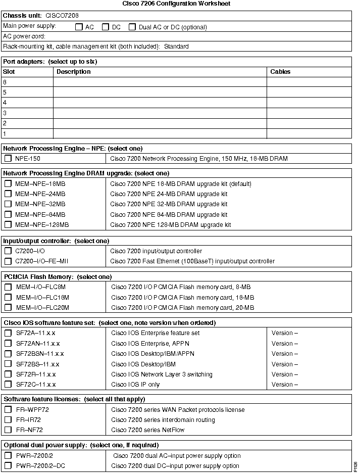
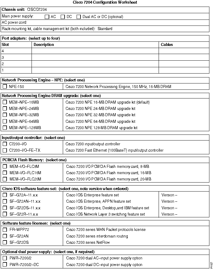
Table 116 lists product numbers that apply to an initial order for a Cisco 7204 or Cisco 7206 router. Note that products with an equal sign (=) can be ordered as spares. Refer to a previous chapter, "Cisco 7200 Series," for tables that include product numbers for spares and upgrades.
To order a router, select a base unit and then order specific options listed in Table 116. The base unit comes with a console cable, an auxiliary cable, an AC power supply, and a power cord. Default components are included in the price of the base unit.
The last pages of this chapter provide worksheets for planning your system.
Table 116 : Cisco 7200 Series Product Numbers
| Description | Product Number |
|---|---|
| Base Unit | |
| Cisco 7206 router (6-slot chassis, 1 AC-input power supply) | CISCO7206 |
| Cisco 7206, 6-slot chassis, 1 DC-input power supply | CISCO7206-DC |
| Cisco 7204 router (4-slot chassis, 1 AC-input power supply) | CISCO7204 |
| Cisco 7204 router (4-slot chassis, 1 DC-input power supply) | CISCO7204-DC |
| Cisco 7200 Power Supply1 | |
| AC-input power supply for United States | PWR-7200-AC= |
| AC-input power supply for Australia | PWR-7200-ACA= |
| AC-input power supply for Europe | PWR-7200-ACE= |
| AC-input power supply for Italy | PWR-7200-ACI= |
| AC-input power supply for United Kingdom | PWR-7200-ACU= |
| Dual AC-input power supply, 280W | PWR-7200/2 |
| DC-input power supply | PWR-7200-DC |
| DC-input power supply (spare) | PWR-7200DC= |
| Dual DC-input power supply | PWR-7200/2DC= |
| Network Processing Engine | |
| Network processing engine, 150 MHz, 16-MB DRAM | NPE-150 |
| Network processing engine, 150 MHz, 16-MB DRAM (spare)2 | NPE-150= |
| Input/Output Controller | |
| Fast Ethernet (100BaseT) input/output controller | C7200-I/O-FE-MII |
| Fast Ethernet (100BaseT) input/output controller (spare) | C7200L-I/O-FE-MII= |
| Input/output controller | C7200-I/O |
| Input/output controller (spare) | C7200-I/O= |
| Flash Memory Cards | |
| 8-MB PCMCIA Flash memory card (default) | MEM-I/O-FLC8M |
| 8-MB PCMCIA Flash memory card (spare)3 | MEM-I/O-FLC8M= |
| 16-MB PCMCIA Flash memory card | MEM-I/O-FLC16M |
| 16-MB PCMCIA Flash memory card (spare)3 | MEM-I/O-FLC16M= |
| 20-MB PCMCIA Flash memory card | MEM-I/O-FLC20M |
| 20-MB PCMCIA Flash memory card (spare)3 | MEM-I/O-FLC20M= |
| Cisco 7200 Network Processing Engine DRAM | |
| 8-MB DRAM upgrade kit (spare) | MEM-NPE-8MB= |
| 16-MB DRAM upgrade (default) | MEM-NPE-16MB |
| 16-MB DRAM upgrade kit (spare) | MEM-NPE-16MB= |
| 24-MB DRAM upgrade kit | MEM-NPE-24MB |
| 32-MB DRAM upgrade kit | MEM-NPE-32MB |
| 32-MB DRAM upgrade kit (spare) | MEM-NPE-32MB= |
| 64-MB DRAM upgrade kit | MEM-NPE-64MB |
| 64-MB DRAM upgrade kit (spare) | MEM-NPE-64MB= |
| 128-MB DRAM upgrade kit | MEM-NPE-128MB |
| 128-MB DRAM upgrade kit (spare) | MEM-NPE-128MB= |
| Port Adapters | |
| 4 Ethernet 10BaseT ports | PA-4E |
| 8 Ethernet 10BaseT ports | PA-8E |
| 1 Fast Ethernet (100BaseT) port | PA-FE-TX
PA-FE-FX |
| 4 synchronous serial ports supporting EIA/TIA-232, EIA/TIA-449, EIA-530, X.21, and V.35 | PA-4T |
| 4 Token Ring ports | PA-4R |
| 5 Ethernet 10BaseFL ports | PA-5EFL |
| 1 FDDI multimode | PA-F-MM |
| 1 FDDI single-mode | PA-F-SM |
| 1 FDDI multimode, full duplex | PA-F/FD-MM |
| 1 FDDI single-mode, full duplex | PA-F/FD-SM |
| HSSI single port | PA-1H |
| HSSI dual port | PA-2H |
| FSIP/SSIP Cables | |
| X.21 high-density male DTE | CAB-X21MT |
| X.21 high-density female CDE | CAB-X21FC |
| EIA/TIA-449 high-density male DTE | CAB-449MT |
| EIA/TIA-449 high-density female DCE | CAB-449FC |
| V.35 high-density male DTE | CAB-V35MT |
| V.35 high-density female DCE | CAB-V35FC |
| EIA/TIA-232 high-density male DTE | CAB-232MT |
| EIA/TIA-232 high-density female DCE | CAB-232FC |
| EIA-530 high-density male DTC | CAB-530MT |
| Software | |
| Software Feature Sets | |
| IP | SF72C-11.2.x4 |
| Desktop and IBM | SF72BS-11.2.x |
| Desktop, IBM and APPN | SF72BSN-11.2.x |
| Enterprise | SF72A-11.2.x |
| Enterprise, APPN5 | SF72AN-11.2.x |
| Network Layer 3 switching | SF72R-11.2.x |
| Software Feature Licenses | |
| WAN Packet Protocols | FR-WPP72, FR-WPP72= |
| Interdomain Routing | FR-IR72, FR-IR72= |
| NetFlow Switching | FR-NF72, FR-NF72= |
Planning Optimum Configurations
This section provides guidelines for planning a configuration with optimum performance. Topics include recommendations for CIP memory, Flash memory cards, and DRAM.
Use Table 117 as a simple means to determine a conservative session capacity for the CIP2 DRAM configurations. If a single feature is being deployed with a single session type, use this table. However, if multiple features are deployed concurrently, use the formulas in Table 118.
Table 117 : CIP2 Memory Guidelines
| Description | Telnet Sessions | Other TCP Sessions | LLC Sessions |
|---|---|---|---|
| CIP2 with 32-MB DRAM | 4,500 | 450 | 2,000 |
| CIP2 with 64-MB DRAM1 | 10,000 | 950 | 4,000 |
Table 118 : CIP2 Memory Formulas
| Description | Formula |
|---|---|
| TCP/IP offload feature only | 2.5 MB + (6 KB x number of Telnet sessions) + (64 KB x number of other TCP sessions) |
| CSAN feature only | 5.0 MB + (12 KB x number of LLC sessions) |
| TCP/IP offload and CSAN concurrently | 6.5 MB + (6 KB x number of telnet sessions) + (64 KB x number of other TCP sessions) + (12 KB x number of LLC sessions) |
For example, if you are configuring the memory for the CSAN feature and you are planning to support 1024 LLC connections, the amount of DRAM required is calculated as follows:
Because the default memory for the CIP2 is 32MB, you will need to order 32 MB of CIP2 DRAM.
If you are configuring the CIP2 for TCP/IP offload and you are planning to support 2048 Telnet sessions and 256 FTP sessions, then the formula is as follows:
This configuration will also require 32 MB of CIP2 DRAM.
Use the following guidelines when ordering Flash memory cards:
For complete information about the Cisco 7000 series Flash memory card, see the section "Flash Memory Cards" in the chapter "Cisco 7000 Series." For complete information about the Cisco 7500 series Flash memory card, see the section "Flash Memory Cards" in the chapter "Cisco 7500 Series."
Use the following guidelines when ordering DRAM for the Cisco 7000 family:
Refer to Table 119 for DRAM size recommendations based on the size of your network. Then, consult with your Cisco system engineer to determine the recommended DRAM configuration for your unique network.
Refer to Table 120 for DRAM size requirements for a Cisco 7500 series router running Cisco IOS Release 11.1, and refer to Table 121 for DRAM size requirements for the 7200 NPE running Cisco IOS Release 11.1 or 11.2.
Refer to Table 122 for default SIMM configurations for the RSP1, RSP2 or RSP7000. These factory defaults are designed so that your initial order can be easily upgraded.
Table 119 : DRAM Size Recommendations---RSP1, RSP2, RSP7000,
7200 NPE
| Network Size | Cisco 7200 | Cisco 7000 | Cisco 7010 | Cisco 7505 | Cisco 7507 | Cisco 7513 | RSP7000 |
|---|---|---|---|---|---|---|---|
| Small1 | 16 MB | 16 MB | 16 MB | 16 MB | 16 MB | 32 MB | 16 MB |
| Medium2 | 16 MB | 16 MB | 16 MB | 32 MB | 32 MB | 32 MB | 32 MB |
| Large3 | 64 MB | 64 MB | 64 MB | 64 MB | 64 MB | 64 MB | 64 MB |
Table 120 : Minimum DRAM Size Requirements---RSP1, RSP2, RSP7000 Running Cisco IOS Release 11.1
| Features | RSP Only | RSP, Slave RSP, and VIP2 | RSP, Slave RSP, and VIP2 |
|---|---|---|---|
| IP only | 16 MB | 24 MB | 32 MB |
| IP, VIP/VIP2 | 16 MB | 24 MB | 32 MB |
| Enterprise | 16 MB | 24 MB | 32 MB |
| Enterprise/APPN | 24 MB | 24 MB | 32 MB |
| Enterprise, VIP/VIP21 | 24 MB | 24 MB | 32 MB |
| Enterprise, APPN, VIP/VIP2 | 24 MB | 24 MB | 32 MB |
| Desktop/IBM | 16 MB | 24 MB | 32 MB |
| Desktop, IBM, VIP/VIP2 | 16 MB | 24 MB | 32 MB |
| Desktop/IBM/APPN | 16 MB | 24 MB | 32 MB |
| Desktop, IBM, APPN, VIP/VIP2 | 16 MB | 24 MB | 32 MB |
| IP/IPX/IBM | 16 MB | 24 MB | 32 MB |
| IP/IPX/IBM/APPN | 16 MB | 24 MB | 32 MB |
Table 121 : Minimum DRAM Size Requirements---7200 NPE Running
Cisco IOS 11.1 or 11.2
| Feature Set | Minimum DRAM Size |
|---|---|
| Network Layer 3 switching | 16 MB |
| IP only | 16 MB |
| Desktop, IBM | 16 MB |
| Desktop, IBM, APPN | 24 MB |
| Enterprise | 16 MB |
| Enterprise + APPN | 24 MB |
Table 122 : SIMM Default Configurations---RSP1, RSP2, RSP7000
| Available DRAM memory | SIMM Size | Number of SIMMs |
|---|---|---|
| 16 MB | 8 MB | 2 |
| 24 MB | 2 4-MB and 2 8-MB | 4 |
| 32 MB | 16 MB | 2 |
| 64 MB | 32 MB | 2 |
| 128 MB | 32 MB | 4 |
Verifying Interface Processor Compatibility
This section describes how to find out if an existing interface processor is compatible with a Cisco 7500 series router or a Cisco 7000 series router upgraded to include an RSP7000. These procedures are described in the section"Investment Protection Program" in the chapter "Interface Processors for the Cisco 7000 Family."
To determine compatibility, use the flowchart in Figure 31 and the compatibility guidelines in Table 123. If you need help in determining a board's part number and revision, see the next section, "Determining Board Part Number and Revision."
Figure 31 : Interface Processor Compatibility Flowchart
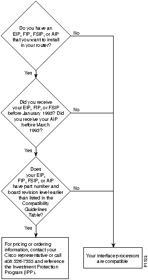
Table 123 : Interface Processor Compatibility Guidelines
| Product Number | Board Part Number1, 2 | Board Revision3, 4 |
|---|---|---|
| CX-AIP-SS | 73-1188-02 | D0 or later |
| CX-AIP-SM | 73-1188-02 | D0 or later |
| CX-AIP-TM | 73-1188-02 | D0 or later |
| CX-AIP-DS3 | -- | Does not require an upgrade |
| CX-AIP-E3 | -- | Does not require an upgrade |
| CX-EIP2 | 73-1129-02 | N0 or later |
| CX-EIP4 | 73-1132-02 | N0 or later |
| CX-EIP6 | 73-0906-02 | N0 or later |
| CX-FIP-MM | 73-0892-03 | M0 or late |
| CX-FIP-MS | 73-1093-03 | M0 or later |
| CX-FIP-SM | 73-1090-03 | M0 or later |
| CX-FIP-SS | 73-1087-03 | M0 or later |
| CX-FSIP4 | 73-1187-05 | A0 or later |
| CX-FSIP8 | 73-1126-05 | A0 or later |
| All other interface processors5 | -- | -- |
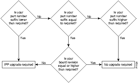
Figure 32 provides a flowchart to use with Table 123.
Figure 32 : Determining Compatibility from Board Part Numbers and Revision Levels
Cisco Board Numbering Conventions
Cisco uses the following conventions when assigning part numbers and revision levels:
To illustrate Cisco's board revision conventions, Table 124 follows one board, 73-0906-XX, through several chronological revisions.
Table 124 : Board Revision Example
| Part Number and Revision | Description |
|---|---|
| 73-0906-01 A0 | Board is released. |
| 73-0906-01 B0 | Board is modified. |
| 73-0906-01 C0 | Board is again modified. |
| 73-0906-01 D0 | Board is again modified. |
| 73-0906-02 A0 | Modifications are rolled into a new fabrication. |
| 73-0906-02 B0 | Board is modified. |
| 73-0906-02 C0 | Board is modified. |
Determining Board Part Number and Revision
You can determine the part number and board revision of your interface processor in one of two ways: inspect the physical board or use the show diagbus command online.
The part number and board revision are typically silk-screened along an edge of the interface processor's printed circuit board:

You can also use the show diagbus command to determine the part number and board revision of your interface processor. The following is an example of a compatible CX-EIP6:
Router# show diagbus

Slot 0:

Physical slot 0, ~physical slot 0xF, logical slot 0, CBus 0

Microcode Status 0x0

Master Enable, LED, WCS Loaded

Board is analyzed

EEPROM format version 1

EIP controller, HW rev 1.5, board revision B0

Serial number: 01652924 Part number: 73-0906-04

Test history: 0x00        RMA number: 00-00-00

Flags: cisco 7000 board; 7500 compatible

 EEPROM contents (hex):

  0x20: 01 00 01 05 00 19 38 BC 49 03 8A 04 00 00 00 00

  0x30: 58 00 00 00 00 00 00 00 00 00 00 00 00 00 00 00

 Slot database information:

Flags: 0x4      Insertion time: 980 (5d20 ago)
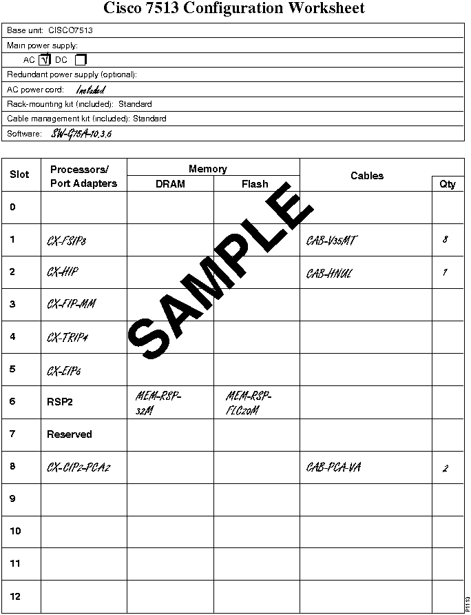
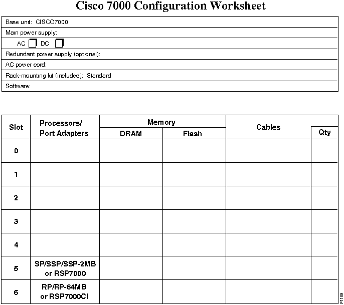
This section contains configuration worksheets for the Cisco 7000 family of routers. Use the tables and configuration guidelines in this chapter to fill out your worksheet. The first worksheet is an example of a completed worksheet for a Cisco 7513.
|
|
Copyright 1988-1996 © Cisco Systems Inc.